• Scam Alert. Members are reminded to NOT send money to buy anything. Don't buy things remote and have it shipped - go get it yourself, pay in person, and take your equipment with you. Scammers have burned people on this forum. Urgency, secrecy, excuses, selling for friend, newish members, FUD, are RED FLAGS. A video conference call is not adequate assurance. Face to face interactions are required. Please report suspicions to the forum admins. Stay Safe - anyone can get scammed.

What air compressor CFM and reservoir size needed to run a 50 amp plasma cutter

Loctite publishes instrucitons on how to proeprly use and apply its products. Here is the how-to page for Loctite 565 (attached photo).

Note:
- leave the first couple of threads clean (not 565)
- The ability to handle pressure increases with time. If the working pressure is over 1000psi, wait 30 minutes.

Jim G

Loctite 565 Thread Sealer Instructions - 1.jpeg
 
I had a chance to at least START the experimentation. I found that both steel and aluminum in the 1/16" thick range cuts very easily and pretty cleanly. The 3/16" aluminum flat bar though, while cutting through easily enough, has a LOT of slag. I will get some suitable small pieces of steel, stainless steel, and aluminum to do more testing with varying psi, amps, and travel speed. I also need to buy a consumables kit for the plasma cutter.

I need to also learn about how much air postflow is actually required, as that is a bIG part of the total air consumed when cutting thin metals and a mix of cut lengths as I plan to do. More Googling required there! Unless someone ehre can educate me on how postflow requirements vary with metal type, thickness, and cutting duration.

One thing i have alreayd noticed is the QUIET. The only sound i hear is the hissing of the plasma and the fan in the plasma cutter machine itself. I think it's actually quieter than TIG welding.

So far so good. :)

Jim G
 
Last edited:
In my research on psot-flow duration, I found a very interesting commentary at a Canadian manufacturer of welding and plasma cutting systems:

about the psi and the hose ID for the air supply:

"
Some of the biggest problems relate to air pressure. Low air pressure leads to poor performance, notably at high amperages.

To check for this condition, try increasing pressure at the machine. If the pressure gauge doesn't move much beyond the optimum setting, adjust pressure at the gas source, because minimum flow rate may not maintain enough pressure through several hundred feet of pipe or hose.

To ensure sufficient pressure at the machine, set the source gauge 30 to 40 PSI higher than the pressure gauge on the machine.

To ensure sufficient air pressure at a plasma machine, you must use a gas hose with at least a 3/8-inch internal diameter and hose fittings that match or exceed the rating recommended in the machine's owner's manual.

Many plasma cutters have built-in regulators with air filters, but good practices call for additional filters and separators on the gas supply to remove water or other contaminants.

Remember that water is highly conductive, and if water enters the torch, it can cause internal arcing that can damage the torch.

"
This supports a suspicion I have had about how much of the external psi supplied actually gets to the plasma cutter, especially as the CFM requirement goes up with thickness or material type.

Now they may be talking about VERY long runs of air line, but their homepage and prcing both suggest that their primary market is small systems for small workshops.

In my testing, I am going to try keeping the external supply psi (i.e. the output psi from the Nitrogen cylinder) notably higher than the INternal psi within the plasma cutter, and see how the cutter performas when I do that versus providing a lower incoming psi.

Jim G
 
In examining an online pdf of an Everlast plasma cutter user manual, I found this interesting statement that applies to their 60 to 80 amp units:
"
Use this as a general rule of thumb for good hand cutting speed and quality: For the first 1/8” of thickness, use 20 amps. After the first 1/8” add 10 amps for every 1/8” after that. For Stainless and Aluminum, use settings that are 40% higher.
"
So, apparently cutting Aluminum or stainless steel with a plasma cutter requires 40% more power than steel. Note also that even with these Everlast units that are more powerful than the less expensive generic "50 amp" lunchbox units, 3/16" Aluminum still requires (20 + 5 to 10) amps x 140% = 35 to 42 amps! I am beginning to see why my 3/16" thick 6061 Aluminum weld coupons have a rough cut result.

Jim G
 
That Everlast manual also says about postflow:

"
As a rule of thumb, use 1 to 2 seconds of post flow for every 10 amps. Longer post flow times may be used in cases where long, uninterrupted cuts are being performed.
"
So, postflow duration versus amps might look like this:

AMPS / Postlow duration
10 / 1-2 sec
20 / 2-4 sec
30 / 3-6 sec
40 / 4-8 sec
50 / 5-10 sec (which explains why the duration is 10 seconds on many machines that have FIXED postflow duration)

This relationship between amperage and postflow is a pretty important thing to know, whether using an air compressor or a gas cylinder as your air supply, since a fixed OR too-long postflow can cause an air compressor to start-stop-restart much more frequently, and a gas cylinder to have to deliver much more gas in postflow than it does in cutting flow!!

Example:

Let's say you are making a cut of 1.5 inches at 20 amps, at the slowest recommended travel speed of 10 inches/minute, using 5 CFM, with 10 seconds of postflow.

Your air or gas consumption for actual cutting is 1.5"/10" x 5 = 0.75 cubic feet

Your air or gas consumption for postflow is 10 sec / 60 sec x 5 = 0.83 cubic feet

Total air or gas usage for that 1.5 inch cut = 0.75 + 0.83 = 1.58 cubic feet

Per the Everlast recommendation, your air or gas consumption for postflow should have been 2 to 4 sec /60 sec x 5 = 0.17 to 0.34 cubic feet.

Your total air or gas usage for that 1.5 inch cut = 0.75 + (0.17 to 0.34) = 0.92 to 1.09 cubic feet

So, you used 1.58 / (0.92 to 1.09) = 45% to 72% more air or gas than you needed to use.

If you are using a 300 cubic foot gas cylinder as the gas supply, you'd get only about 190 such cuts out of that clyinder, versus 300 if you adjusted the postflow to what it SHOULD have been.

On long cuts, the air or gas wastage on excess postflow is proportionately much smaller, but the CFM used, from EITHER a compressor or a gas cylinder, is problematic:

Let's say you are making a cut of 20 inches at 20 amps, at the slowest recommended travel speed of 10 inches/minute, using 5 CFM, with 10 seconds of postflow.

Your air or gas consumption for actual cutting is 20"/10" x 5 = 10 cubic feet!

Your air or gas consumption for postflow is 10 sec / 60 sec x 5 = 0.83 cubic feet

Total air or gas usage for that 1.5 inch cut = 10.0 + 0.83 = 10.83 cubic feet!

Per the Everlast recommendation, your air or gas consumption for postflow should have been 2 to 4 sec /60 sec x 5 = 0.17 to 0.34 cubic feet.

Your total air or gas usage for that 20 inch cut = 10.0 + (0.17 to 0.34) = 10.17 to 10.34 cubic feet

So, you used only 10.83 / (10.17 to 10.34) = 4.7% to 6.5 % more air or gas than you needed to use.

BUT, look at the total cubic feet used!

If you are using a 30 gallon air compressor, that 30 gallons = only 4 cubic feet. So you blew through your entire air tank less than 40% of the way through the cut and started cycling your compressor. Hopefully, its NET (not gross) air delivery capability exceeds the 5 net CFM you need to make the cut.

If you are using a 300 cubic feet gas cylinder, you have used up about 3.3% of its gas. If you are making such lengthy cuts rarely, no problem. But if you are doing one after the other, you are are going to want a bigger cylinder.

Running these numbers really opens your eyes . . .

Jim G
 
Deep within it (page 19 ! ) the Everlast user manual contains this scary warning:

"
Regulator/Filter/Water Trap. This regulates the cutting pressure of the unit. To adjust: Pull up firmly but gently on the regulator knob until the detent clicks (about 1/8” or 3mm). Rotate clockwise to increase pressure. Rotate counterclockwise to decrease pressure. Observe the pressure and indicator lights on the front of the machine to reach the ideal pressure for the process you have selected. Push the knob back down after adjusting to lock-in the pressure setting. WARNING! Do not supply more than 90 psi to the regulator or damage and/or severe injury may occur.
"
(The bolding in the quote above is by me)

This would appear to prohibit applying more psi from the regulator on the air compressor or gas cylinder feeding the plasma cutter, as a way to overcome unknown (and likely varying) airline pressure and CFM losses on the way to the plasma cutter, unless you also install your own regulator in the airline just before it enters the regulator on the plasma cutting machine.

Jim G
 
In my testing, I am going to try keeping the external supply psi (i.e. the output psi from the Nitrogen cylinder) notably higher than the INternal psi within the plasma cutter, and see how the cutter performas when I do that versus providing a lower incoming psi.

WARNING! Do not supply more than 90 psi to the regulator or damage and/or severe injury may occur.

Jim, I think you're on to a useful approach.

Every regulator will have a maximum supply pressure; your unit's internal regulator may be rated for more/less supply pressure than the Everlast unit. Along with the previous advice to use large diameter hose and fittings and short hose lengths, maximizing the supply pressure is helpful to ensuring adequate flow at sufficient pressure. If you feel that the supply pressure rating on your unit's regulator is too low, you could install an external regulator, with a higher supply pressure rating at sufficient flow rating, immediately before your plasma cutter.

In operation:
At the tank, regulate the pressure to the safe maximum for your hose and fittings.
At the supply entering the plasma cutter, regulate the pressure to the safe maximum for your internal regulator.
In the plasma cutter, regulate the pressure to minimum required for acceptable cutting performance.
Yes, I checked, and the instructions for my plasma cutter say to set its built-in regulator for no more than 75 psi. The instructions are unclear as to whether that means I should ALSO not let more than 75 psi come to the machine, or whether it is ok to feed a higher psi to the machine, but keep the INTERNAL regulator set to 75 psi or lower.

I assume adding an external regulator just before the machine would add more restriction and therefor increase psi loss and cfm loss at the entry to the machine? So, if it is unnecessary, that would be nice to know.

Jim G
 

Attachments

  • SNAG-2023-02-17 11.25.01 AM.jpg
    SNAG-2023-02-17 11.25.01 AM.jpg
    71.6 KB · Views: 5
  • SNAG-2023-02-17 11.25.55 AM.jpg
    SNAG-2023-02-17 11.25.55 AM.jpg
    85.8 KB · Views: 5
So @JimGnitecki did I understand you ultimately selected a 2400 psi N2 cylinder?

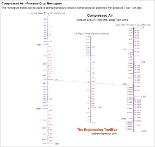
Re pressure drop of lines flowing gas, these links may be useful

Yes, I was offered a 2300 or 2400 psi N2 cylinder and went with that.

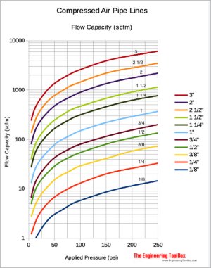
If i am reading that first full colour graph correctly, a 3/8" line can flow 20 CFM, but a 1/4" line only 10 CFM, so my 3/8" line with 1/4" fittings is likely a bit above 10 CFM capability. That's good.

I did post a question on Amazon.ca on the page advertising the BestArc plasma cutter, about how high a LINE psi can be fed to the INPUT of the Bestarc, BEFORE its internal regulator. Hopefully, I'll get an answer. I like to eliminate unknowns whenever I can.

Jim G
 
This postflow air or gas consumption seems to be a big deal with the plasma cutter manufacturers. The user manual for one Hypertherm model says the following:

"

How the system handles postflow for marking

Postflow is gas that flows from the torch in order to cool the consumables after the plasma arc
extinguishes. When you use air (or nitrogen) for marking applications, the duration of postflow is
10 seconds. The system recognizes when argon is being used and decreases postflow from
10 seconds to 3 seconds in order to minimize gas usage. To achieve 3-second postflow:
The system must be set to Gouge/Marking mode.

The output current must be set to 10 – 25 A.

The plasma arc must be sustained for a minimum of 0.5 seconds.

There are 2 scenarios in which postflow is 10 seconds even when argon is used because the
plasma arc is not sustained long enough to produce 3-second postflow:
When the torch fires without transferring the pilot arc to the workpiece

In some dimpling applications where the plasma arc is sustained for less than 0.5 seconds

"
"Marking" is when the plasma cutter is used to "mark" workpieces with informaiton or patterns, versus cutting the workpieces. Note the extra emphasis on reducing unnecessary postflow when Argon gas is used for quality reasons, because of its cost.

Jim G
 
Its been a while since I looked at this stuff, but I think pressure drop in fittings is a bit different again. If I remember correctly, some equate the fitting (ID, type of bend, passage length...) to X length of pipe equivalent so you can refer to same pipe charts & estimate their drop contribution. Then there are orifice calculators that have D/d & other parameters?

I also recall regulators may have their own criteria in terms of flow rate, delta-P limit or relative-P. Best to check the specs. I know this is a big deal with CO2 if freeze off conditions occur (not related to water content, its a phase diagram thing). But I don't think this pertains to N2. I heard of guys doing airbrushing with N2, maybe this is why. No noise!

There are multiple reaosns that some operators use Nitrogen or Argon for plasma cutting or airbrushing. Quality is one. Noise is another. Eliminating oxidation is another. Better temperature stability is yet another (this reason, along with zero moisture content no matter what, is why Nitrogen is used in vehicle tires).

Jim G
 
Aurbrushing sounds surprising at first given that airbrush artists usualy take minutes or hours versus seconds to do their work, and Nitrogen is not tnat cheap, but then you realize that an airbrush uses VERY little air or gas. When artists use airbrushes to paint for example, where the air or gas pressure must not fluctuate, the air compressor or Nitrogen source can be very small because the CFM is so low!

Jim G
 
If i am reading that first full colour graph correctly, a 3/8" line can flow 20 CFM, but a 1/4" line only 10 CFM, so my 3/8" line with 1/4" fittings is likely a bit above 10 CFM capability. That's good.

Hi Jim, you are sure on one amazing journey. My hat is off to you for being so persistent.

While it is reasonable for you to make the assumption above about 1/4" fittings, it isn't a given. Gasses are not as sensitive as liquids, but generally the higher the pressure the more liquid like they become. While you can probably calculate the overall system flow rate capacity, I'd recommend measuring it instead with a flow gauge or meter. I don't have a price in my head but I don't think they are out of sight.

By measuring the actual flows, you can better tune your system because you know the actual results vs guessing or estimating them. You might find you need bigger fittings because the fittings have more of an affect on flow than you guessed.

A few pressure gauges here and there in your system will also be helpful while tuning it.
I would like to keep the system as simple and robust as practical, so adding a flow meter and an additional pressure gauge is not attractive to me, especially since the additional hardware would need to somehow hang precariously off the water filter male 1/4 NOT fitting on the plasma cutter. This also works against keeping the system portable and compact, so that it can be put away when not in use, as my shop space is under 400 sq ft.

I like the small footprint of the N2 cylinder and the small shelf space requirement of the plasma cutter, and the ease of setting up each time I want to use the plasma cutter.

Jim G
 
I would like to keep the system as simple and robust as practical, so adding a flow meter and an additional pressure gauge is not attractive to me,

I would never advocate a permanent install. Just a temporary setup so you know what is happening instead of guessing.
 
I would never advocate a permanent install. Just a temporary setup so you know what is happening instead of guessing.
What specifically do I buy that would fit via 1/4 NPT quick disconnects between my airline and the plasma cutter? The combination regulator/psi gage/flow meters I have seen have Argon gas fillings versus NPT threads that can accept male or female QD fittings. (I am very new to this gas flow hardware stuff!)

Jim G
 
Back
Top