• Scam Alert. Members are reminded to NOT send money to buy anything. Don't buy things remote and have it shipped - go get it yourself, pay in person, and take your equipment with you. Scammers have burned people on this forum. Urgency, secrecy, excuses, selling for friend, newish members, FUD, are RED FLAGS. A video conference call is not adequate assurance. Face to face interactions are required. Please report suspicions to the forum admins. Stay Safe - anyone can get scammed.

Welcome to Westwood Metalworks, What is he building in there?

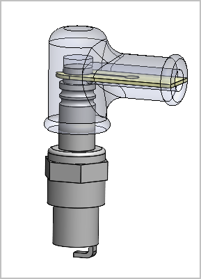
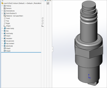
What kind of spark plug & ignition system will it use? FYI, I drew up an RCEXL 1/4-32 dummy plug just measuring off a physical one (when I was messing around with boots & connector clips etc.). Not sure what formats you could import but it wasn't very onerous to model. BTW, these plugs are significantly cheaper on various AliExpress hobby stores, so shop around. I think there are different flavors but I'm going off what RC guys are saying which is they all run about the same, so there's that.

1765255592292.png1765255836965.png
 
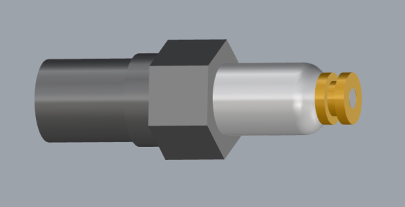
I modeled the upshur one for now, but will most likely use a commercial RC plug to get it going. Graduating to a shop made version eventually once I've actually got a running engine instead of chasing too many variables from the start.

1765284378385.png

Spark, carb and ignition are all stuff I'm going to have to decide to stick to the model, or stray and use commercial. It might be a bit of mix n match, but I'll at least "try" to stick to original as much as I can. But my goal is more oriented to running model than faithful original.
 
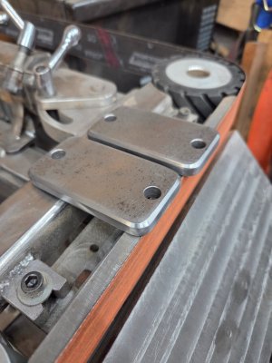
Almost got sucked into the couch gravity when I got home, but I fought it off enough to go out and make my grinder feet. The last peices I need to weld on before I can strip it all down for paint. Then start a build thread about it.

20251217_183403.jpg

Too late for welding tonight, but hopefully I'll get to it this weekend.
 
I like Newtons first law of motion. An object at rest, stays at rest, and an object in motion stays in motion. If I come home, and just keep going, I'll keep going until midnight or I fall down tired. If I come home and sit down, it's game over. It got me Monday and Tuesday night, I wasn't going to let it get me again lol. It was close though.... Come weekends or days off, same deal, once I get started, I'm good. Getting started sometimes though.....That can take a day or two.
 
Almost got sucked into the couch gravity when I got home, but I fought it off enough to go out and make my grinder feet. The last peices I need to weld on before I can strip it all down for paint. Then start a build thread about it.

View attachment 75004

Too late for welding tonight, but hopefully I'll get to it this weekend.
You should paint your shelf at the same time....
 
Been a busy holiday around here and I've not managed to get as much shop time in as I wanted/hoped. I did a big cleanup out there, and some inventory of material piled up in the shop and out in the barn the last few days. There's always a lot of projects on the go here, so It's nice to know where things are, and what I have, and where I'm at (I forget sometimes....). Nothing sucks more than saving a piece to build something from, and then using it for something else, only to realize that it's gone when you get back on the other project......surely I can't be the only guy that works like that......

Anyway, most of these projects using these materials where ones previously designed and ready to go, in various stages of construction, but lost in the hard drive crash. So I've started remodeling a couple of them the past week or so to hopefully get the back on track now that the belt grinder is done. One of them is my bandsawmill I just updated here.

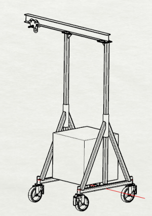
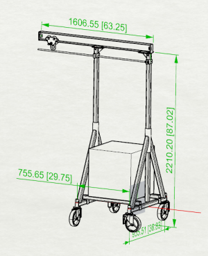
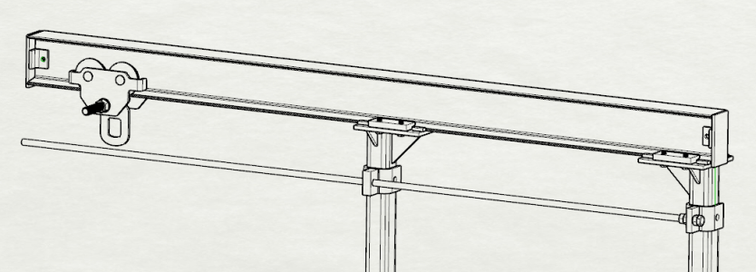
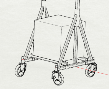
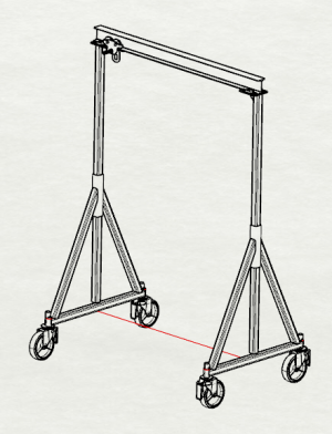
Another is a small gantry crane for lifting and moving stuff around the shop. It's built from 2x2x1/4" square for the frame which I have a bunch of lying around, and the beam is a S4x9.5 (as far as I can tell) x 63" long. Legs are adjustable vertically, and I was thinking 2 hitch pins for load, and a pinch bolt to take up play. After modeling it based on what I have (and the recent discussion in the other thread), I'm going to look for a larger beam, as that s4 isn't really good for much (but it's the only one I have right now). Not that I want to lift a lot with it, The scaffold casters are rated at 900lbs each, so If I could lift 500-750lbs with this I'd be happy, Most things would be well under that in the 200-400 range. I just want to keep it small, and only about 5' wide. Things like this will be very handy as I age, so I'm trying to future proof now.... I designed this so the beam can slide on the vertical frame, and if I picked up a weight box between the frame, I can cantilever it out for better reach (Perhaps with some cross tie bars too), like a mini versa lift. Who knows, this may never even get built 😀.
1767377328124.png1767378174015.png1767380351054.png
I just want a small easily maneuverable gantry for lifting and positioning awkward stuff around the shop. Any thoughts or design critique from the engineers on board are more than welcome.

With the shop now cleaned up so where I can finally work i have to go out and cut some steel for another project on the go. I have WAY too much material piled up everywhere, it's time to start using it and getting it out of the way......
1767377189323.png1767378430409.png
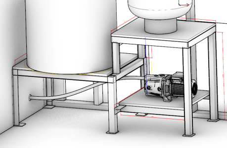
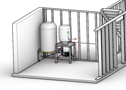
Next up is a new water heater and well pump stand (her list, not mine). Last fall I trenched in a new line to the well, and this is the next step in that process (no need to rush into things...). This moves the water heater and well pump to the other side of the utility room where the new line comes in. This will make better use of this utility room, then I can move my basement workbench into here from out in the main room, which will allow me to have a ventilated hood for the 3d printers and painting etc. This is one of those projects where having the above crane would be handy. It's not super heavy. I may still make it in 2 pieces and either weld, or bolt it together down there.

Things move slow around here....but they DO move....Just not always in the direction I want them to though lol. Happy new year!

 
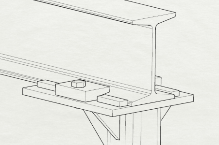
Am not "one of the engineers on board", but I would make the tabs that hold the I beam crossbar to the uprights full length along their seat on the uprights, and have three bolts on each side, not one.

The larger question would be how to adjust the position of the legs along the I beam when a change is required? Climbing up on a ladder with a wrench will deal with the bolts, but once they are loosed the legs and I beam will "rack" against each other and make sliding the legs nearly impossible IMHO.

The only possible, and partial, solution I can see is to make the seats of the uprights the I beam sits on much longer and as friction-free as possible so that they can *somehow* slide along the I beam to adjust the leg separation and positions. How you get the friction down to that point I don't know!

As for how to generate the force to actually move the legs along the I beam, the only thing I can think of is to get some I beam with a rack already fitted to it. I have a couple of pieces of beam with rack attached I found somewhere, but what it was originally from I don't know.

With a rack you would then have the chance at least to design a pinion and housing attached to the top of each leg, which with a long "extension bar" could possibly have the mechanical advantage to move the legs along the beam, (or more likely the beam moves and the legs don't) overcoming the leverage exerted by those long legs and all their weight, friction on the floor etc. etc. Not a likely prospect however, though if it could be got to work, at least the bolts on each leg could be arranged so that the same extension bar could be used to loosen and tighten them. 😀

OK, that was an interesting think-through... I'd suggest heavy duty barn door track attached to the joists. 😉
 
Last edited:
Am not "one of the engineers on board", but I would make the tabs that hold the I beam crossbar to the uprights full length along their seat on the uprights, and have three bolts on each side, not one.
Not a bad idea, might consider making the clamp seat wider for more fasteners. I typed the rest below and came back to add that I like that, and will definitely make them wider for at least two bolts.
The larger question would be how to adjust the position of the legs along the I beam when a change is required? Climbing up on a ladder with a wrench will deal with the bolts, but once they are loosed the legs and I beam will "rack" against each other and make sliding the legs nearly impossible IMHO.
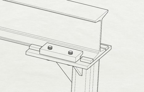
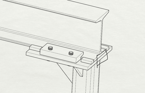
The little blocks beside the clamp are welded to the top plate, preventing the beam from racking. I'm also going to flip the bolts and thread the clamps so I can get them from underneath.
The only possible, and partial, solution I can see is to make the seats of the uprights the I beam sits on much longer and as friction-free as possible so that they can *somehow* slide along the I beam to adjust the leg separation and positions. How you get the friction down to that point I don't know!

As for how to generate the force to actually move the legs along the I beam, the only thing I can think of is to get some I beam with a rack already fitted to it. I have a couple of pieces of beam with rack attached I found somewhere, but what it was originally from I don't know.

With a rack you would then have the chance at least to design a pinion and housing attached to the top of each leg, which with a long "extension bar" could possibly have the mechanical advantage to move the legs along the beam, overcoming the leverage exerted by those long legs and all their weight, friction on the floor etc. etc. Not a likely prospect however, thought if it cold be got to work, at least the bolts on each leg could be arranged so that the same extension bar could be used to loosen and tighten them.

OK, that was an interesting think-through... I'd suggest heavy duty barn door track bolted to the joists. 😉

As for sliding the beam, I don't think it'll be a big problem. The pic makes it bigger than is seams, The height to the bottom of the beam at it's lowest is 87" which I can reach comfortably. I can pull them together with a come a long, or a couple taps with a 2lb purse should get it moving easily. Adding a rack would follow the same path that all my other projects suffer from lol. While typing that thought about welding some hooks/loops on the end of the beam, and that'll not only give additional pick points, but also allow me to spread them out with a come a long too. My little 1/4t is perfect for stuff like that. But I still think just loosening the bolts, and giving a slight lift on the beam while pushing in/out will move it where it needs pretty easily.
 
Any thoughts or design critique from the engineers on board are more than welcome.

The problem is that the law makes it difficult for licensed engineers to comment on such things. Personally, I try to keep a healthy distance between safe lift design and my license. I tried to explain that earlier.

That said, there is some room to make comments on the relative suitability of one approach vs another as long as there is zero chance that any comments made could be misinterpreted as approvals.

In my own experience, and nuances set aside, I find that most seal level skilled trades and in fact most machinists are waaaay ahead of what Redneck Eddy might do in his laneway. Often as not, I can just let the whole discussion follow its own course and totally avoid getting Involved.
 
I understand the reluctance from any professional to giving advice in written form on a message board. Even though there's no rubber stamp on a forum post, you're potentially exposing yourself in a "well he said...." typ of situation. Especially lifting devices. My experience building lifting devices and improvising in the field has always simply been to overbuild stuff. I think I'm usually pretty good at visualizing force vectors and keeping proportions right, but still, it's nice to know if you're in the ballpark with an idea sometimes, or even the same city as the ballpark without asking for specific parking and seating directions......My gut check tells me I should be fine with this for my intended needs, but I feel as though I'm walking the line with beam selection, and don't have much of a safety factor at my desired WLL range. I'll keep my eye out for a larger beam before building.

1767532463076.png

Made a quick change to the top pad, which I think will be much better.
 
Not a bad idea, might consider making the clamp seat wider for more fasteners. I typed the rest below and came back to add that I like that, and will definitely make them wider for at least two bolts.

The little blocks beside the clamp are welded to the top plate, preventing the beam from racking. I'm also going to flip the bolts and thread the clamps so I can get them from underneath.
With all due respect, IMHO as soon as the bolts are loosened the legs will splay, probably outwards, very slightly which will reduce the contact area between the bottom face of the I beam and the upper face of the leg tops to a small "edge" with inevitable results. Which end of the top face of the legs will jam will depend on whether the legs splayed inwards or outwards.
As for sliding the beam, I don't think it'll be a big problem. The pic makes it bigger than is seams, The height to the bottom of the beam at it's lowest is 87" which I can reach comfortably. I can pull them together with a come a long, or a couple taps with a 2lb purse should get it moving easily. Adding a rack would follow the same path that all my other projects suffer from lol. While typing that thought about welding some hooks/loops on the end of the beam, and that'll not only give additional pick points, but also allow me to spread them out with a come a long too. My little 1/4t is perfect for stuff like that. But I still think just loosening the bolts, and giving a slight lift on the beam while pushing in/out will move it where it needs pretty easily.

The only concept I can come up with is something like a retired lead screw or some other large and heavy threaded rod, collared on one leg and with the other leg riding along the screw on a captive nut with a large heavy hand wheel at the collared end. The trouble is that mounting it where it should be directly under the beam puts it right in the working area, so a modified trolley would be needed which would extend below the rod, on both sides of course.

Putting the rod above the beam might work, but stepping back for a moment, what is gained by having this kind of adjustment in any case? The length of the beam is a constant constraint whether in use or being stored. Closer legs might allow heavier loads to be lifted, or perhaps to pass through tighter spaces in a workshop - if the beam is high enough to clear the obstacles whatever they are. Very little could be lifted from one end of the beam with the legs moved closer together. Interesting exercise, but does it pass the cost-benefit test?

If a gantry could be made with the beam permanently fixed on one leg and sliding on the other, with the beam hinged as close to the fixed end as possible, so that the two legs could be slid together and the projecting beam hinged down for storage, that might be worth having, but no rod possible in that scenario. Maybe a removable push-pull hydraulic cylinder with a porta-power connection? 😉
 
Last edited:
Made a quick change to the top pad, which I think will be much better.

I suspect that you are concerned about drilling through the bottom plate of the beam. If so, your fear is mostly unfounded. The primary structural benefit of the top and bottom flanges takes place at the middle of the span and is reduced as you move from the middle to the ends.

If you are still concerned, move the attachments to the center of the upright section of the beam where the impact of a hole on the structural strength of the beam, is virtually zero.

This advice should not be considered to be approval or disapproval of any part of your design. I provide it simply as basic engineering principles for your information and consideration.
 
Not an engineer, so my suggestions are provided with no warranty, but based on experience. The beam needs a stop, so the vertical support can’t slip out from under the beam.
 

Attachments

  • https___canadianhobbymetalworkers.com_attachments_1767532463076-png.75925_.png
    https___canadianhobbymetalworkers.com_attachments_1767532463076-png.75925_.png
    577.7 KB · Views: 0
I suspect that you are concerned about drilling through the bottom plate of the beam. If so, your fear is mostly unfounded. The primary structural benefit of the top and bottom flanges takes place at the middle of the span and is reduced as you move from the middle to the ends.

If you are still concerned, move the attachments to the center of the upright section of the beam where the impact of a hole on the structural strength of the beam, is virtually zero.

This advice should not be considered to be approval or disapproval of any part of your design. I provide it simply as basic engineering principles for your information and consideration.
Thanks. No I wasn't concerned about drilling the beam. I'm aware of that's how connections are made, and to keep them from the middle of a span. I Just came up with that clamp idea while designing and thought it would be nice to be able to have infinite travel. Not married to it, and not opposed to just drilling for a bolted connection, but as you say I'd like to keep from drilling out in the middle, and I'd like to retain the cantilever function. Both of those things can't happen if I fasten that way, And I think the cantilever would be a huge benefit around here.

Are your concerns about the clamp coming from an inadequate strength/poor joint design standpoint, or from a complexity of design one?

Junque, I get what you're saying about the racking, and I agree that that will be the reaction. I still think it'll be manageable without heroics though. This is a pretty small gantry, as shown that's only a 4" beam. I think I'll be able to either muscle it around, Tap it around, or use a come a long or porta pack if needed to push/pull when needed. I should be able to stand, reach up and lift the beam while pulling the upright in/out pretty easy.
1767561289113.png

In the event that it's unmanageable I think a simple pin on bracket near the top of the uprights with some all thread spanning the gap would work to push or pull them apart with a battery impact gun pretty easy. Something like this below. Either way I'll cross that bridge when I get there if needed.

1767560235935.png

Whydontu, I was planning on a bolt on stop for a beam trolley, but hadn't thought about the beam itself. Doing something like above accomplishes both. Thanks for pointing that out, I'll add it.

We went skiing this morning and while riding the chairlift in between runs today I had lots of time to daydream and imagineer (both this and the sawmill). For the counterweight I have two slide out drawers/carts full of steel under my stairs. They're easily modified to pick and set on some cross braces across the bottom. I wouldn't be lifting much while cantilevered. The thing that springs to mind as the most likely would be pulling the table off the mill, or saddle off the surface grinder. I don't have room in here for an engine crane, but this should fit fine (famous last words...). I might even shorten up the width a couple more inches.
1767559044135.png

I have a few more thoughts/questions, but I'll come back to it later...
 
Back
Top