-
Scam Alert. Members are reminded to NOT send money to buy anything. Don't buy things remote and have it shipped - go get it yourself, pay in person, and take your equipment with you. Scammers have burned people on this forum. Urgency, secrecy, excuses, selling for friend, newish members, FUD, are RED FLAGS. A video conference call is not adequate assurance. Face to face interactions are required. Please report suspicions to the forum admins. Stay Safe - anyone can get scammed.
-
Several Regions have held meetups already, but others are being planned or are evaluating the interest. The Calgary Area Meetup is set for Saturday July 12th at 10am. The signup thread is here! Arbutus has also explored interest in a Fraser Valley meetup but it seems members either missed his thread or had other plans. Let him know if you are interested in a meetup later in the year by posting here! Slowpoke is trying to pull together an Ottawa area meetup later this summer. No date has been selected yet, so let him know if you are interested here! We are not aware of any other meetups being planned this year. If you are interested in doing something in your area, let everyone know and make it happen! Meetups are a great way to make new machining friends and get hands on help in your area. Don’t be shy, sign up and come, or plan your own meetup!
You are using an out of date browser. It may not display this or other websites correctly.
You should upgrade or use an alternative browser.
You should upgrade or use an alternative browser.
Unbalanced 4 jaw on my 12x36
- Thread starter Proxule
- Start date
Proxule
Ultra Member
Sorry, I'm a bit late to this thread but want to help.
I feel like it's really unlikely to be chucks since all three have similar vibration nodes. Usually different masses have different vibration nodes even if they are equally unbalanced. Since you changed the belt and motor and since they are silky smooth, I think that's unlikely too.
If you did find an unbalanced chuck, the wheel weight method (installed as close to the gear head as possible) would work well. I've used that for drive shafts and other rotating parts with excellent success - even better than the static balance method you originally asked about. Dynamic balance is always superior to static.
But I didn't read if you ran it without any chucks installed at all. I highly recommend that. You can do it without waiting for chucks. Although you probably don't want to hear it, I am suspicious of your headstock and especially the big gears in there. Of course, there is also the spindle itself.......
Thanks for the reply, The chuck arrived a couple days ago and I been multi tasking with the family and the shop. I managed to balance the chuck as the new one is also the same - Of course it is.....
I dynamically balanced the chuck using my DTI mounted on a pedestal and the tip touching the headstock area of my lathe.
It took exactly 81 grams of weight to balance this chuck. It now moves the DTI 1 or 2 tenths, I made a video showing this.
ANy one want to buy a 8" 4 jaw D1-4 camlock lol
Thanks for the replies and suggestions, was a fun journey. Clearly they do not balance their chucks, Their master tech said it was good to go. Mmmm hmmm, good to go!
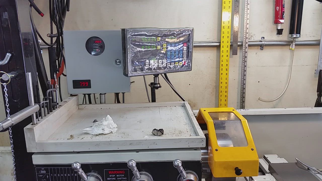
If any one is curious about the LCD and custom control panel I made. I will post more info.
It was my take on the LCD / e stop, speed POT, and inch button.
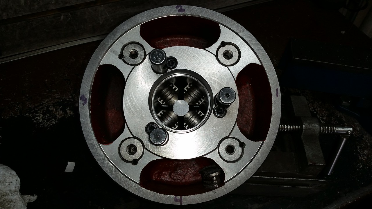
Picture of the backside of the chuck, The pocket was terribly over cast and spent a ton of time die grinding and then fine tuned the last 5 grams with holes,
http://imgur.com/gallery/MYRxspZ
Last edited:
Proxule
Ultra Member
@Proxule I have an idea, one that will need a well fitting faceplate. I'll do some calculations and we'll talk once you get your new one.
I have a new faceplate that also is egg shaped and does not mate up properly to the spindle nose, I will make adjustments as time permits but the balance issue is now solved, Thanks for your ideas and dropping in to assist.
Thanks for the reply, The chuck arrived a couple days ago and I been multi tasking with the family and the shop. I managed to balance the chuck as the new one is also the same - Of course it is.....
I dynamically balanced the chuck using my DTI mounted on a pedestal and the tip touching the headstock area of my lathe.
It took exactly 81 grams of weight to balance this chuck. It now moves the DTI 1 or 2 tenths, I made a video showing this.
ANy one want to buy a 8" 4 jaw D1-4 camlock lol
Thanks for the replies and suggestions, was a fun journey. Clearly they do not balance their chucks, Their master tech said it was good to go. Mmmm hmmm, good to go!
If any one is curious about the LCD and custom control panel I made. I will post more info.
It was my take on the LCD / e stop, speed POT, and inch button.
Picture of the backside of the chuck, The pocket was terribly over cast and spent a ton of time die grinding and then fine tuned the last 5 grams with holes,
http://imgur.com/gallery/MYRxspZ
Great stuff! Well done!
Amazing difference! Makes me want to go check on mine!

Proxule
Ultra Member
That first vibration video is insane. Good for you pursuing. Where did you distribute the weight? Was it kind of trial & error running on the lathe or you worked out some kind of external balancing jig?.
I divided my chuck into 4 equal sections, I then moved a magnet of unknown weight every 10 or 15 degrees around the chuck body and spinning the chuck up to around 600 rpm, Once I found the spot that made it better I would then mark the extremes where the chuck was better then progressively worse, So now we know our area of interest.
Then its just trial and error with more and more weight, Until you have little or no vibrations according to the dial indicator or DTI.
In my case it was 81 grams, and meant that opposite of the weights was the heavy spot. Confirmed with the ugly over cast pockets ( a blind man could see the discrepancy )
I mounted my DTI off the lathe on a mcguyver stand / pedestal stand. And the probe was touching the headstock area.
I also had the ability to adjust the speed on the fly to find the worst vibration rpm / node VIA my vfd.
Funny enough the listed RPMS are not true, and they are only accurate at 50HZ - Good ol kind canada!
It was a lot of trial, Not much error once you found your section where the weights needed to be added.
Thanks\
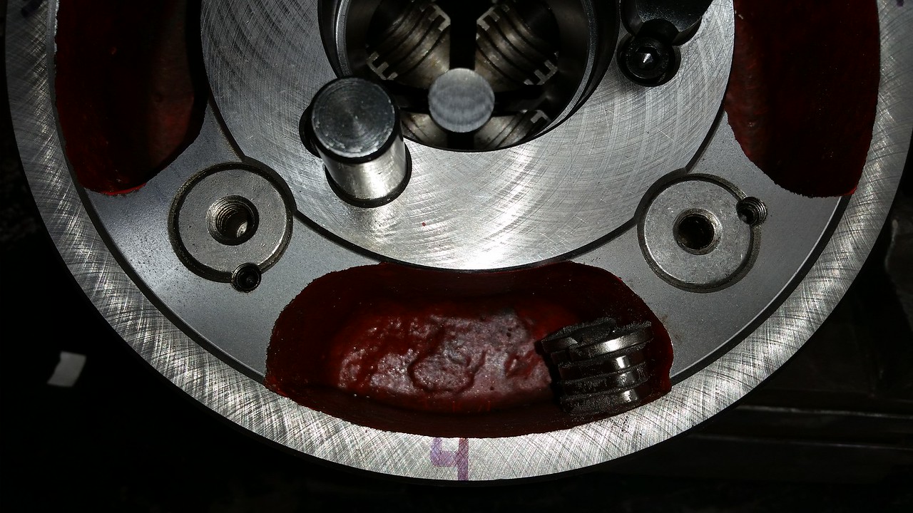
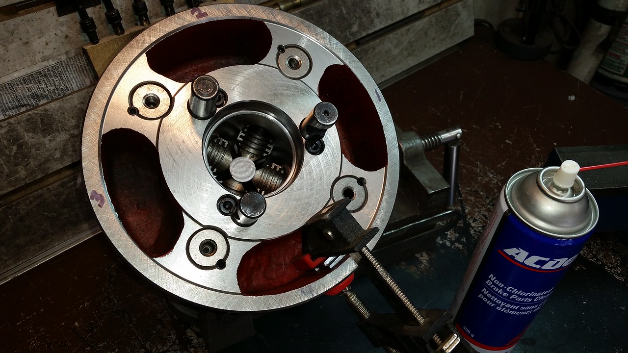
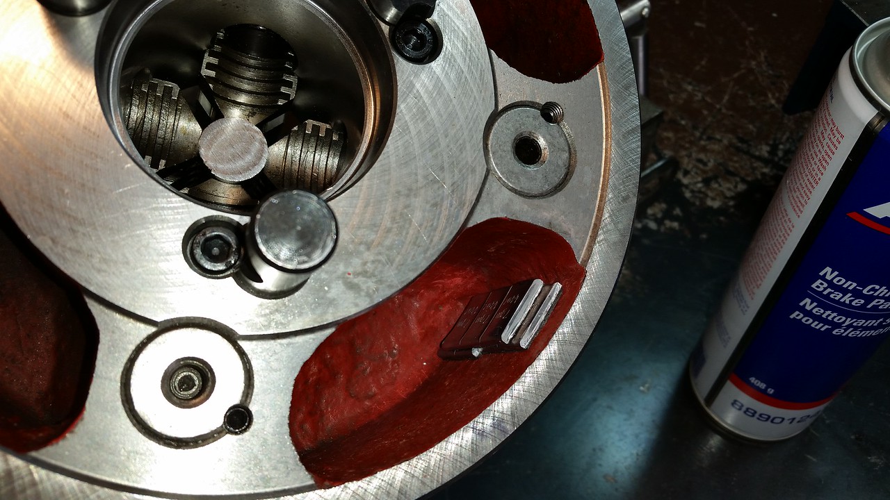
Thanks for posting this, I have not used my 4 jaw much and never really noticed any vibration when I did. After watching your video I mounted my 4 jaw and checked for vibration all the way from 10 to 2000 spindle rpm. I found that there was a pronounced vibration that started about 775 rpm and went away about 830rpm. When I checked the 4 cavities on the back of the chuck I noticed that 1 of them is about .100 deeper than the others. I have a bunch of small magnets from some hard drives I scrapped so I used the same method you described for balancing and found that 49 grams placed at 1 end of the deep cavity reduced the vibration to a negligible amount. I then used 7 seven gram stick on wheel weights in place of the magnets for a permanent fix. I did a small video where you can see the level of vibration by watching the DRO display, there is a short pause in the middle where the stack of magnets disappears off the top of the lathe and magically makes it's way into the back of the chuck to show before and after. Click on the last picture to link to the video.
Last edited:
Proxule
Ultra Member
I like your style, Wish I had sticky wheel weights, would beat playing around with volume calculations when I was drilling holes.Thanks for posting this, I have not used my 4 jaw much and never really noticed any vibration when I did. After watching your video I mounted my 4 jaw and checked for vibration all the way from 10 to 2000 spindle rpm. I found that there was a pronounced vibration that started about 775 rpm and went away about 830rpm. When I checked the 4 cavities on the back of the chuck I noticed that 1 of them is about .100 deeper than the others. I have a bunch of small magnets from some hard drives I scrapped so I used the same method you described for balancing and found that 49 grams placed at 1 end of the deep cavity reduced the vibration to a negligible amount. I then used 7 seven gram stick on wheel weights in place of the magnets for a permanent fix. I did a small video where you can see the level of vibration by watching the DRO display, there is a short pause in the middle where the stack of magnets disappears off the top of the lathe and magically makes it's way into the back of the chuck to show before and after. Click on the last picture to link to the video.
I noticed you kept your chuck guard, Hats off to you, That was the first item I removed lol
Thanks for commenting
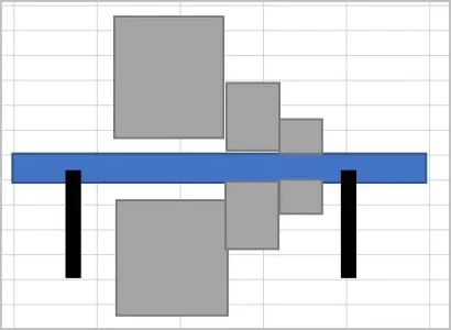
Do you guys think this is worth a try? I'm only thinking out loud here
- with chuck mounted in lathe, grip some nicely finished stock (ideally like a long dowel pin). It protrudes slightly forward of jaws & rearward of chuck mount flange face
- DTI the dowel so its now concentric to spindle axis
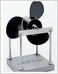
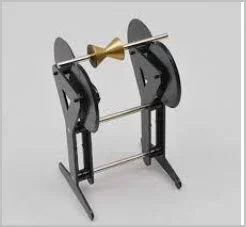
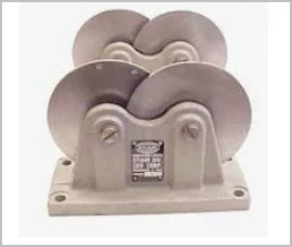
- remove assembly, mount to balancing jig..... which you of course have laying around LoL, sample pictures
- do the weight tweaking
What I'm wondering is static too slow a process? isnt this how they do grinding wheels & such at much smaller imbalance amounts? Maybe if its out of whack this much, getting it close off the lathe is worth it?
I almost hate to ask, running it like that for any sustained trial & error period cant be wonderful for the spindle bearings.
- with chuck mounted in lathe, grip some nicely finished stock (ideally like a long dowel pin). It protrudes slightly forward of jaws & rearward of chuck mount flange face
- DTI the dowel so its now concentric to spindle axis
- remove assembly, mount to balancing jig..... which you of course have laying around LoL, sample pictures
- do the weight tweaking
What I'm wondering is static too slow a process? isnt this how they do grinding wheels & such at much smaller imbalance amounts? Maybe if its out of whack this much, getting it close off the lathe is worth it?
I almost hate to ask, running it like that for any sustained trial & error period cant be wonderful for the spindle bearings.
Attachments
Great idea Peter. I have a motor cycle wheel balancer that will work perfectly for that. I'll check it out and let you know.
In the old days, we did static balance on car wheels. It worked. Then people got fussier. It didn't work anymore. Nowadays, all good balancing is dynamic.
A static balance cannot address harmonics with other components.
So ya, I think any balance is better than no balance. But dynamic is "usually" better still.
A static balance cannot address harmonics with other components.
So ya, I think any balance is better than no balance. But dynamic is "usually" better still.
The other thing I was wondering (and I think we chatted about this). if there is any minor fit-up discrepancy between how an otherwise perfect chuck meets an otherwise perfect spindle where the chuck is cocked at a slight angle to spindle axis, I can see that making imbalance that you wouldn't see statically removed from lathe, but would rear its head running (dynamic). By that I mean backplate is cocked up on the spindle nose because the taper is not quite matching. Or the backplate adapter is tapered slightly. But I think in this case the casting mismatch looks to be the culprit. When its noticeable to the eye & its a mass difference between iron & air & out near the extremity, that is bound to have consequences.
3/4 into this video kind of shows the effect where the axis is drilled off axis to an otherwise balanced part.
3/4 into this video kind of shows the effect where the axis is drilled off axis to an otherwise balanced part.
As Peter suggested, I checked the static balance of my 4 jaw on the motorcycle balancer I built many years ago. I removed the weights I had installed earlier to see how it would react on the static balancer. The 49 grams or 1.75oz of imbalance are very obvious and it wound up using exactly the same amount of weight in exactly the same place to off set the chuck's imbalance. You can see how obvious it is in the short video.
https://johnconroy.smugmug.com/GH1440W-Lathe/n-QdB9WL/i-F58kzdV/A
https://johnconroy.smugmug.com/GH1440W-Lathe/n-QdB9WL/i-F58kzdV/A
Well that was pretty gratifying to watch. A 3-jaw scroll would be easier yet because it grips the bar just by tightening, no DTI really involved. And once you have it dialed in should never really vary because jaws are extending equally. I have some spare ~15mm OD matched bearings kicking around, I think I'm going to make me a balancer tool.
Last edited:
When I built my balancer I used some 8mm ID X 22mm OD bearings and removed the rubber seals. Each time I use it I flush any dust out of the bearings with WD40 and follow with a drop of 10wt spindle oil to reduce rolling friction as much as possible. The accuracy for static balance is very good, 3 grams (1/8 oz) is an obvious heavy spot on an 18" motorcycle wheel. Something as small in diameter as an 8" chuck you need about 7 grams of imbalance to be really obvious.
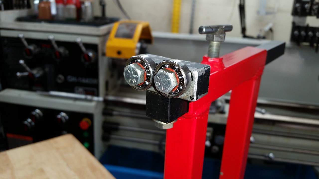
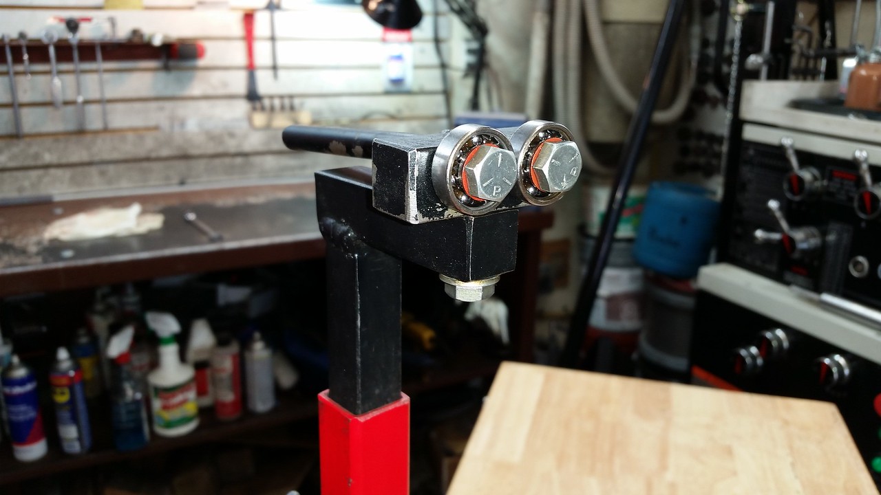
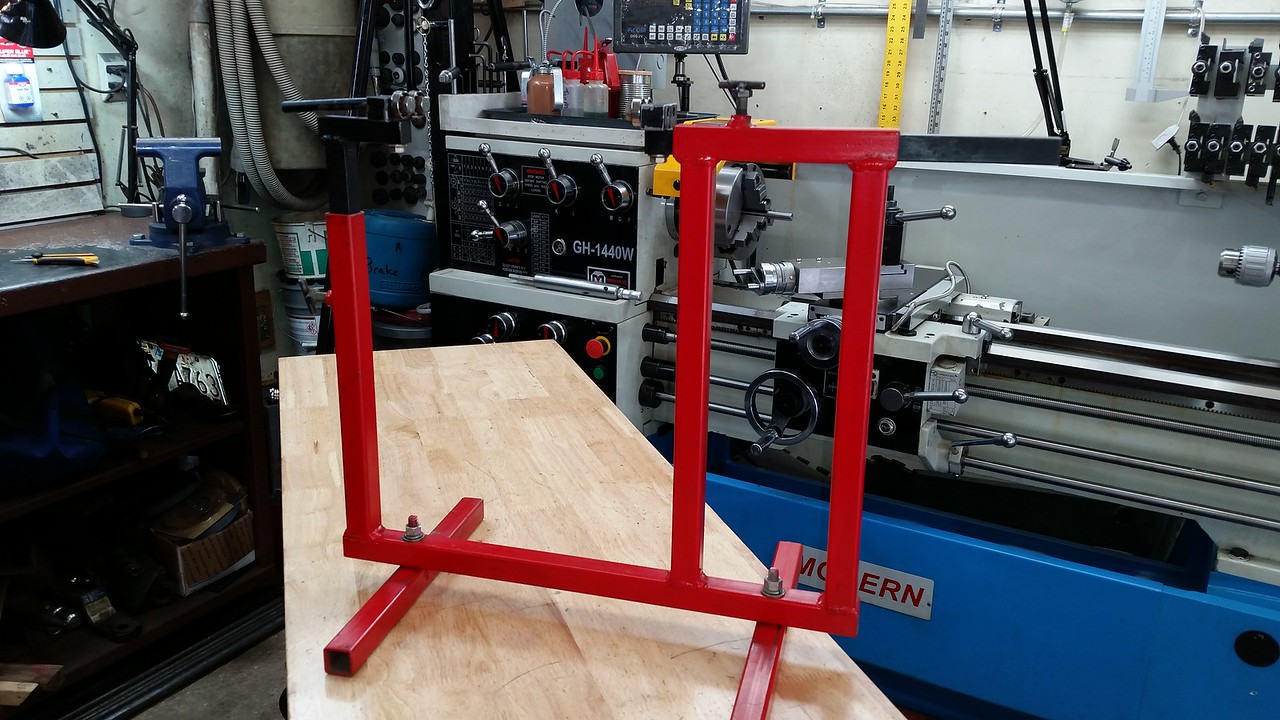
The right side is adjustable for width and the left for height. Quite often motorcycle axles are different diameters from one end to the other.
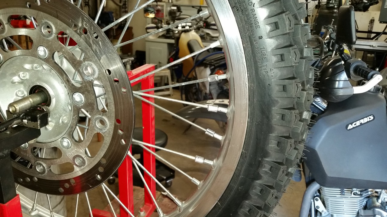
The right side is adjustable for width and the left for height. Quite often motorcycle axles are different diameters from one end to the other.
That's right, you can just see a bit of the red 8mm ID X 10 mm OD fiber washer under the head of the 5/16" hex head cap screw. There is another one on the back side of the bearing that allows clearance for the outer race to turn and not rub on the block. The OD of the outer races of the 2 bearings are spaced 1mm apart.