• Scam Alert. Members are reminded to NOT send money to buy anything. Don't buy things remote and have it shipped - go get it yourself, pay in person, and take your equipment with you. Scammers have burned people on this forum. Urgency, secrecy, excuses, selling for friend, newish members, FUD, are RED FLAGS. A video conference call is not adequate assurance. Face to face interactions are required. Please report suspicions to the forum admins. Stay Safe - anyone can get scammed.

trlvn's terrific travelling RF30 tale

Note I now have one 1/2-20 bolt, one 7/16-14 bolt and two 7/16 nut-and-bolt connections. What a dog's breakfast.

Yup, shoulda used Helicoils......

You need to get a kit and try them at least once. You will be converted to helicoilism in the blink of an eye......
 
Yup, shoulda used Helicoils......

You need to get a kit and try them at least once. You will be converted to helicoilism in the blink of an eye......
yabut...I checked the 7/16-14 helicoil repair kit online and it specified a 29/64 drill before tapping for the coil. That would still have left me with malformed threading for the coil. Here is what the *best* hole looked like after drilling out to 29/64:

best hole after drilling.jpg


BTW, as somebody mentioned long ago, the fasteners are metric. But weird sizes. For example the fixed portion of the belt cover is attached with several bolts that measure 7.75 mm (as close as I can figure). Which is about 0.100" less than 5/16 inch. Didn't check the threading but a 5/16-18 nut will not go on. The head size is 12 mm which is, of course, awfully close to 1/2 inch.

I still don't know for sure but possibly the original bolts that have given me so many problems were actually a weird metric size. Maybe 11 or 11.25 mm with a very coarse thread. IOW, darn close to 7/16-14 but not actually. 'Bubba' may have just assumed they were 7/16-14 and forced in some bolts of that size. He clearly had these apart as this is where he added his home-made mount for the DRO screen. If my theory is true, it would account for the really crappy fit of the 7/16-14 bolts and explain why the threads stripped out so easily.

One of these days, I will use a helicoil. I'm also pretty sure using nuts on the underside is the better solution in this case.

Craig
 
Sounds like Bubba did a real good job of screwing things up. If your hinged lid doesn't fit then leave it off. I'm not even sure where my cover is, 'tis a pain in the butt when you have to change belts around.
 
yabut...I checked the 7/16-14 helicoil repair kit online and it specified a 29/64 drill before tapping for the coil. That would still have left me with malformed threading for the coil.

Yabut nothing Craig.

The beauty of a helicoil is that you are not changing pitch. You are actually using the old threads to guide the new ones. So you WANT some threads left after drilling. Then you tap the OLD threads a bit deeper, insert the coil, and then use the old bolts!

Try it, you will be singing hallelujah with the rest of us......
Agreed, it's one of the few easy repairs that are actually better than new in most cases.
 
Agreed, it's one of the few easy repairs that are actually better than new in most cases.

Sing it brother, sing it with me!

Hallelujah, hallelujah.... Hallelujah!

We just have to get Craig to try it and he will be a helicoilism convert too.

@trlvn - think about this for a moment. @John Conroy recommended helicoils to repair the spider on my full size Bridgeport. Those four 1/2" Bolts hold the top and bottom half of the BP together. Yet you lift the whole machine by the top half. That's thousands of pounds hanging on a helicoil.

It turned out that my spider was broken so I just replaced it, but I had the helicoil kit to repair it sitting on my bench cuz the minute I read his note, I knew he was right. It's too late for the big hole, but you might still consider it for the others.

But as I said before, even if you can't use them on this job, you should try them. They absolutely belong in your repair arsenal.
Come on in Craig, the water is warm and the kool aid is pretty tasty...... Yer just one wierd tap and a funky insert away from the promised land.....;)
Too much?:p
 
Much faster progress now that I'm done f@rting around with the mangled threaded holes. All the parts cleaned up easily with some paint thinner and/or WD-40. There is very little wear on this machine. Just a few hints of shiny spots on the sliding surfaces. The screws and nuts for X and Y look really good. In the shot below, the saddle is reinstalled along with the Y screw.

saddle reinstalled.jpg


The saddle is actually awkward to work with since I elected not to take the DRO scales off. The saddle is surprisingly heavy and the scales are rather delicate. Needed to be careful not to damage them.

Reinstalling the table and the other bits and bobs was also straightforward. I may add an oiling system in the future but I need to think about how best to get around the DRO, gibs and other obstructions.

all reassembled.jpg


Everything is powered up and works as expected.

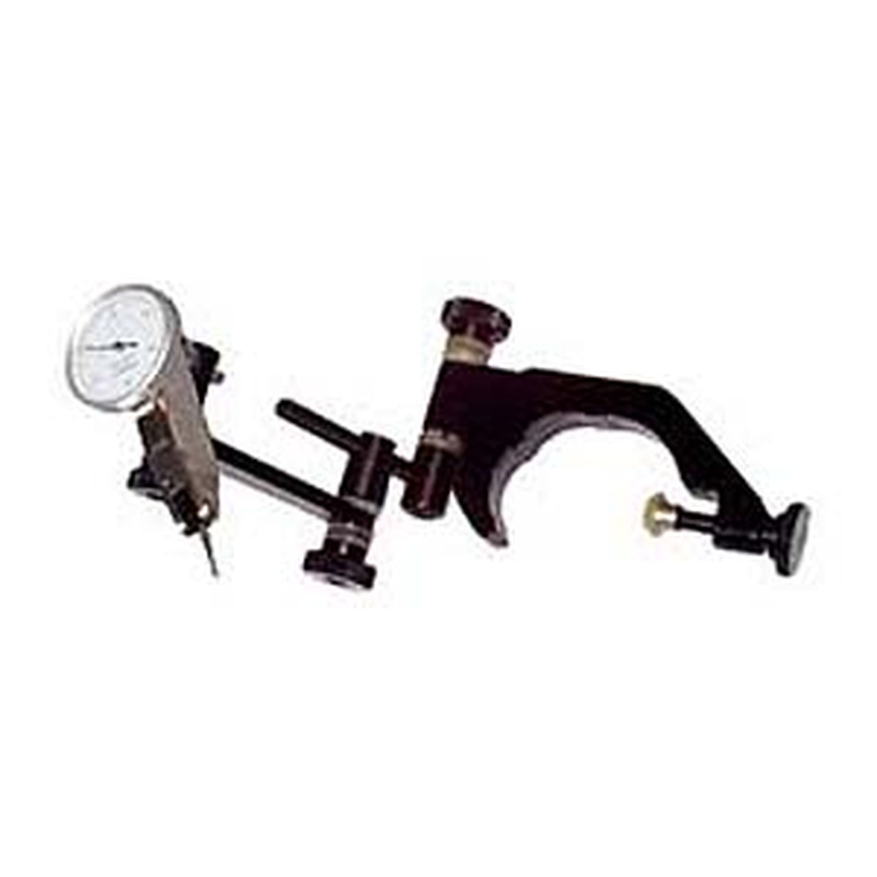
Next steps are to tidy up the wiring and check the tram. I picked up an indicator holder from Busybee:

B2129_org.1435536854.jpg


Unfortunately, the screw that locks it to the quill sticks out to far and runs into the depth-stop knob. I need to have a closer look at it and see if maybe I can modify it to work on my machine.

Craig
 
I am late to this discussion but would like to throw an idea out there. Put a piece of all thread in the semi threaded hole and put a nut on the all thread from underneath. Now the all thread is treated like a protruding stud and the column is lowered onto it.
 
Great job Craig. It's looking terrific. I got one of those Busy Bee Quill Holders 5 years ago or so too. I made a new quill clamp section to fit my machine to replace the original piece. Nothing fancy, just a piece of wood with a hole saw cut in it. I use it on my lathe tailstock one in a while too. Yours reminds me that I always wanted to make a better one out of aluminium plate. Another job for the new mill!

Yup, using my tools to make more tools for my tools!
 
Tramming the head was not a lot of fun. I re-watched Marc Lucuyer's video (That Lazy Machinist channel):


I used a half-thou indicator to take some measurements around a diameter of nearly 8 inches. Over the 8 inches, the head was leaning forward by 3 thous and to the right by about 5.5 or 6 thous.

tramming setup.jpg


I also did a little test where I raised the head and then extended the quill pretty much to its maximum. The measurements were almost precisely the same. From that, I conclude that the column and quill are both pretty straight and parallel to one another.

I used an old feeler gauge set as the source for my shim stock. Just drilled out the rivet holding all the leaves together and Voila!

Unfortunately, I got myself turned around and shimmed the wrong direction to start with. Eventually, I got on the right track although it is all to easy to miss that a shim has now made the low side into the high side. After that, increasing the shim thickness then just makes things worse! Duh!

In the end, the fore-and-aft alignment is out by about 1/4 thou. The side-to-side alignment is not as good at nearly 1 thou off. That is with a 4 thou shim at the back of the column and a 5 thou shim on the right. I can always come back and try again. I'm curious if the measurements will change after doing some actual work.

BTW, the fore-and-aft measurement can be easily changed by a thou or more just by pushing up on the belt cover. Say 20 pounds of pressure? I imagine the head will lift during roughing cuts and hopefully behave for finer finishing cuts.

The next step for the mill is to decide between the 4 and 6 inch vises and get one mounted and trammed in. And then maybe actually make a test cut! But I also need to bring my big tool chest down from the garage and assemble the newly-purchased work table. And move the metal lathe from one of the shop to the other. I've been working _on_ the shop since September. Sooner or later, I'd like to _use_ the shop to make something.

Craig
 
I used an old feeler gauge set as the source for my shim stock.
That's cheating,,,,,,,, I like it lol
Are you torquing the bolts to the same lbs/kg after each adjustment? When I was leveling the lathe I found that 10/15 lbs more/less on one corner made a difference in the level. I don't know what it would work out to in thou but I could move the bubble the full length of the vial by adding more torque to one bolt. I ended up at 70lbs on the torque-o-meter using 1/2 inch bolts.
One thing I'm lacking is a torque wrench. I try to pull the same amount each time, but...

Craig
 
Where did the indicator holder come from?
Almost all my measurement stuff is from auction box lots so I have an embarrassment of arms and whatnot for dial indicators. (Although some is metric and other bits are imperial sized and therefore not all compatible.) OTOH, I have very little for dial test indicators. I actually used parts from a surface gauge to hold the DTI.

In fact, I would have preferred to use my Verdict dti as it has a much bigger dial. But I couldn't easily find something to go between the collet in the mill and the dti. So I just squinted at the Starrett!

Craig
 
BTW, the fore-and-aft measurement can be easily changed by a thou or more just by pushing up on the belt cover. Say 20 pounds of pressure? I imagine the head will lift during roughing cuts and hopefully behave for finer finishing cuts.

This is to be expected. Even 6" bar steel bends to the force of a baby - its not if, it's only how much. That's one of the reasons why we have small mills and big mills and huge mills. It's no big deal.

I used an old feeler gauge set as the source for my shim stock. Just drilled out the rivet holding all the leaves together and Voila!

I do the same thing. I bought a half dozen feeler gauge sets that were on sale cheap a few years ago for exactly the same purpose. But I didnt drill out the hinge - I just snip the leaves off with tin snips as needed. It's not cheating, it's being frugal and savy.
 
Sorry that I haven't updated this thread in some time. I've been plugging away at a slow pace. Just to step back though, the following picture was from October 18.

storage room framed.jpg


To get to that point, I'd temporarily moved a bunch of stuff out to a storage pod on the driveway. And sold some stuff, donated more and hauled even more to the dump. Here, the storage room floor is down and the framing is up ready for drywall and plywood.

Fast forward to today, and this is the view in the same general direction:

tool chest doesnt fit.jpg


I'm going to have to rearrange, though. The big red tool chest just doesn't fit on that side. It blocks the lathe too much. Hopefully I can fit it on the other side of the room without it cutting off that end of the shop.

I mentioned in another thread that I'd bought a work table from Princess Auto (on sale!). I'm pretty happy with it so far. The one on display would wiggle and rock but mine is decently solid. I had to use a christmas tree bit to enlarge a couple of holes during assembly but that was a pretty minor detail. The tools and whatnot on top of it need to find homes in the tool chest and cabinets.

I'm planning to make an extra wooden top out of 2-by stock to go on the work table. That way, the wood top will be above the lip on the edges and I'll be able to work on all sides. Also should be quieter for the grinder and tabletop bandsaw.

Another ToDo item is under cabinet lights above the metal lathe. I'm thinking some kind of strip light. Really only needs to be about 18 inches above the working section of the bed. Suggestions?

Lots still to be done but it is starting to feel like I just might get through this!

Craig
 
The big red tool chest just doesn't fit on that side. It blocks the lathe too much. Hopefully I can fit it on the other side of the room without it cutting off that end of the shop.

Agreed. You need access. It won't go under the cabinet on that same wall, but the work table currently on the left could and wouldn't interfere with the lathe. I'd just swap the tool chest and work horse for now. That way you could also put lathe things on the workhorse - chucks, collet sets, etc.

I think I see tool holders on the lathe table in front of the motor. I'd put lathe tools (chuck keys, quick change wrench, etc) there instead and I'd make a shelf on the wall above the lathe for the tool holders.

I bought some partial Allen key sets at auctions and used them as a mine for the keys I need for my lathe so they are dedicated to the job. I hate digging around for the right size key. It's better if they are in a handy hole in a shelf. Change gear key far left, cross slide lock second from left, tool holder key third from left, etc. Etc.

I plan to do the same thing for my mill but it's further down the priority list right now.

Another ToDo item is under cabinet lights above the metal lathe. I'm thinking some kind of strip light. Really only needs to be about 18 inches above the working section of the bed. Suggestions?

None. I'll be looking for your input on that one.

My lathe has a dedicated 24V halogen light attached to the cross slide that I HATE! It is forever blowing bulbs that are hard to find and hard to change. I recently got a batch of bulbs that appear to have been incorrectly labelled as the very first one fried the lamp switch. That whole lighting thing needs a redesign. Same goes for the mill. I'm thinking about re-purposing two of my old post style indicator holders for battery powered lights or at least 120V with small wires.

If you are determined to have broader coverage lighting, go get one of those 48" LED fixtures they sell for workshops and garages at TSC or Crappy Tire and either mount it under the cabinet or hang it on chains.
 
Back
Top