Worth mentioning if you happen to have lathe DRO you can dispense with the dial gage measuring along the bed which is probably <2" displacement anyways & subject to alignment errors in 2 planes. Then you can utilize the full length of compound which will increase accuracy because its probably 4X longer, providing the traverse gage is accurately aligned. Lots of ways to skin the cat. All this compound fiddle farting is why I lust for a taper cutting attachment. NEXT lathe lol.
-
Scam Alert. Members are reminded to NOT send money to buy anything. Don't buy things remote and have it shipped - go get it yourself, pay in person, and take your equipment with you. Scammers have burned people on this forum. Urgency, secrecy, excuses, selling for friend, newish members, FUD, are RED FLAGS. A video conference call is not adequate assurance. Face to face interactions are required. Please report suspicions to the forum admins. Stay Safe - anyone can get scammed.
-
Several Regions have held meetups already, but others are being planned or are evaluating the interest. The Calgary Area Meetup is set for Saturday July 12th at 10am. The signup thread is here! Arbutus has also explored interest in a Fraser Valley meetup but it seems members either missed his thread or had other plans. Let him know if you are interested in a meetup later in the year by posting here! Slowpoke is trying to pull together an Ottawa area meetup later this summer. No date has been selected yet, so let him know if you are interested here! We are not aware of any other meetups being planned this year. If you are interested in doing something in your area, let everyone know and make it happen! Meetups are a great way to make new machining friends and get hands on help in your area. Don’t be shy, sign up and come, or plan your own meetup!
You are using an out of date browser. It may not display this or other websites correctly.
You should upgrade or use an alternative browser.
You should upgrade or use an alternative browser.
Tool Tools to set angle on compound fairly accurately?
- Thread starter StevSmar
- Start date
Tool
Tom Kitta
Ultra Member
It started raining here today so planting is on hold.
I'm not really a fan of actual sine bars when setting compound angles. I like to take the arc-tangent of the resulting compound displacement divided by its associated horizontal carriage displacement. The result is the compound angle. Its really as simple as that.
Here is the Basic Trigonometry.
View attachment 47928
Note that using these definitions, the lengths don't need to be unitized. They can be anything.
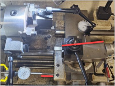
Here is an example setup.
View attachment 47924
This photo is not really what I do, but it will serve as a better example photo than what I really do. Fundamentally, I don't like long indicator holder arms because they bend. So my actual process has the compound right under the chuck and both indicators are attached to the chuck. Note that some of this long arm bending is negated by locating the rear of the horizontal indicator so that it touches my gear box. (Outlined in yellow on the photo.) But the compound indicator is on a long arm suspended in the air - which basically sucks.
It is VERY IMPORTANT that the two indicators be set perpendicular to the two axis of the lathe so that they measure the actual desired displacement.
Note that the angle set on my compound is 7 degrees or as close to that as my eyes will allow.
View attachment 47926
Both indicators are zeroed. Then the cross-slide is moved by whatever amount you want and then readings are taken on both indicators. It is not necessary to move certain discrete amounts like 1" or 2". However, the longer the distances, the better the resolution of the result.
In this case, the compound displacement was 0.124 and the cross-slide movement was 1.000. It isn't necessary that it be 1.000 it just makes the division math easier.
Opp/Adj is 0.124/1.000 = 0.124
ArcTan of 0.124 = 7.068 deg.
It also doesn't matter if your indicators are metric or imperial as long as they are both the same.
It's actually easier to measure an angle this way than it is to set it to a specific angle. But either way, it's WAAAY more accurate than using angle gauges and such.
If your lathe and indicator setups are such that hysteresis of the readings cannot be avoided, then I suggest that several readings be taken in each direction and the results averaged.
Don't assume that one reading nails it. It is important to be aware of hysteresis. On this particular setup, I found that repeating the long axis in both directions resulted in about 2 thou change in the compound reading depending on which way the two indicator plungers were moving (in or out). That 2 thou changed the angle to 7.18 degrees from 7.07. So in this case, I would average those two angles to 7.12 degrees. This difference is the reason that I like short rigid indicator arms. You can never get zero difference but it's nice to get close.
In this setup, the difference was half the first one. Which makes sense because only one arm is bending and the other is straight.
View attachment 47929
As always, setting up something like this as a demo, spawns ideas. I have a carriage stop indicator planned which would eliminate arm flexing for the carriage measurement, but I should make something short and rigid to mount the compound indicator on. That would eliminate arm flex for both indicator holders leaving only the internal hysteresis of the indicators themselves to deal with.
It is very easy and quick to check the angle this way - on the DRO you see one leg of the triangle, on the indicator you see the other leg. Now using basic math you can get the angle precisely.
But to set the angle you may need to do it few times. Each time getting more precise.
This comes in handy a lot - a lot of tapers need to be quite precise.
I guess you could try to do the same check with taper attachment.
Why wait? Make your own TTA. I did.All this compound fiddle farting is why I lust for a taper cutting attachment. NEXT lathe lol.
It also depends on the type of gib. Whether it is a tapered wedge shape adjusted for tension with a single screw at the end, or a flat wedge shape adjusted with 2 screws from the side.
I've never worried about that other than an initial check when I first got the lathe. Either Gibb method depends on locating the compound via the opposite slide and neither one distorts the compound in any meaningful way. Maybe I am being overly optimistic or missing something though.....
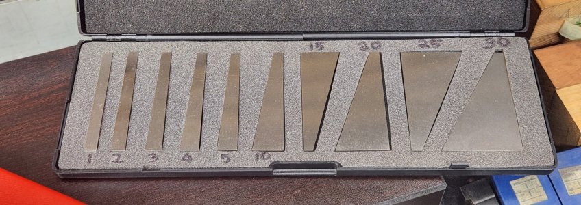
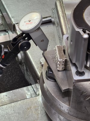
If you have a set of angle blocks, just attach the appropriate angle block to the side of your compound, then move the cross-slide forward and back while nudging the compound until the indicator reads zero. In this particular case I had to make a 14.5° angle plate to do an internal acme thread, and it's held in place with a magnet.
Therefore, no math!
Therefore, no math!
Attachments
Worth mentioning if you happen to have lathe DRO you can dispense with the dial gage measuring along the bed which is probably <2" displacement anyways & subject to alignment errors in 2 planes. Then you can utilize the full length of compound which will increase accuracy because its probably 4X longer, providing the traverse gage is accurately aligned. Lots of ways to skin the cat.
I was going to mention how lucky those are who have a DRO, but I provided my method in order to help @StevSmar who was interested in seeing how its done using indicators and Trig.
Now, if only there was a convenient way to mount a DRO Scale on the compound! If I recall correctly, my Ditron has a setting that will calculate the angle directly. I do plan a scale inside my cross-slide, and I'm thinking that a digital edge finder could be used to measure the length of the opposite side of the triangle. (touch off, move the carriage, touch off again - the difference is the length)
All this compound fiddle farting is why I lust for a taper cutting attachment. NEXT lathe lol.
I think I'm about to learn something....... Other than the additional resolution provided by the extra length, why is measuring the angle of a taper attachment any less fiddle farty than measuring on a compound?
PS - I don't have a taper attachment either. They are still available for my lathe ($$$) and time is slowly closing on my ability to get one. So your answer might be pivotal for me.
In this particular case I had to make a 14.5° angle plate to do an internal acme thread, and it's held in place with a magnet.
Very nice!
Where did you get that magnet!
I got it, and a bunch of other dibs and drabs from my dad years ago. And he had it for years before that.Very nice!
Where did you get that magnet!
I got it, and a bunch of other dibs and drabs from my dad years ago. And he had it for years before that.
I see. Nice!
How well do the blocks stack using that magnet?
I see your compound has degree marks all the way around! VERY NICE! Another project I have to finish this summer.
Why the sad face? He's still alive and kicking. Well, maybe not kicking, but alive! He turns 89 in August.I got it, and a bunch of other dibs and drabs from my dad years ago. And he had it for years before that.
Why the sad face? He's still alive and kicking. Well, maybe not kicking, but alive! He turns 89 in August.
Oh! Well then I'll FIX IT to celebrate! 😛
Worth mentioning if you happen to have lathe DRO you can dispense with the dial gage measuring along the bed which is probably <2" displacement anyways & subject to alignment errors in 2 planes. Then you can utilize the full length of compound which will increase accuracy because it’s hen I spoke of probably 4X longer, providing the traverse gage is accurately aligned. Lots of ways to skin the cat. All this compound fiddle farting is why I lust for a taper cutting attachment. NEXT lathe lol.
When I spoke in another thread of how much I like the taper turning attachment I have, I don’t think I highlighted the contribution the DRO makes for me to make the job easier.
Before DRO I was doing the indicator shuffle but now there’s no comparison for speed of setup or resolution (and hopefully accuracy!) obtained from the DRO for the reasons @PeterT talks about.
@Susquatch Since you asked, for me the DRO/TTA combination lets me measure both the carriage and cross distances to the accuracy of the DRO (purported to be 1u) and get the angle. The only fiddly part is zeroing in on just the right adjustment of the angled slide but you have to do that anyhow.
I set the carriage travel to as long a distance as practical then tweak the cross measurement (via the angled slide) to obtain the correct sine travel for my angle - always using the same carriage distance. I don’t but you could set two hard stops on the carriage to define the cosine travel while you’re doing the setup.
Make sense?
D 😎
Last edited:
For those without indicators or gauge blocks, here is another way to set a compound angle for cutting tapers.
If your hand wheels have reliable graduations, you can use them to measure the sides of the triangle. The carriage movement can be read directly to get the length of the adjacent leg. A digital edge finder works perfect for consistent measuring of the cross-slide movement to get the length of the opposite leg, but almost any method of displacement detection will get you within a degree or so.
As always, when using the hand wheel dials, don't forget to take up the backlash.
I have a plan. The swiveling rear bar isn't a big issue (I've stored some of your good ideas). Its how to implement the temporary detachment of the cross feed nut from cross slide & then returning it back to normal mode when taper cutting is done. It will involve mods to the cross slide & nut, so being precautious to the point of inactivity haha. I'm going to pull it apart again anyways to replace the nut & possibly leadscrew once the wear gets to irritation level as both are getting worn. So I'll have a closer look at the table underside to confirm if my idea will work. Mostly its a matter of sucking up the kahunas.Why wait? Make your own TTA. I did.
Its how to implement the temporary detachment of the cross feed nut from cross slide & then returning it back to normal mode when taper cutting is done.
The design for the one for my lathe is permanently attached in use. No need to disconnect. If you want I could send you what I have on it.
Tom Kitta
Ultra Member
If you have a set of angle blocks, just attach the appropriate angle block to the side of your compound, then move the cross-slide forward and back while nudging the compound until the indicator reads zero. In this particular case I had to make a 14.5° angle plate to do an internal acme thread, and it's held in place with a magnet.
Therefore, no math!
Yeah but the problem is the super strange angles that seem to be used.
Sure send away. I've looked at a few designs but that doesn't mean I've seen them all. Ideas always welcome. Some are telescoping leadscrew assemblies where the threads are always in the nut, but there is another mode of disengagement. Some are what amounts to undoing the fastener that engages the nut to cross slide underside (more or less what I'm thinking of). Ultimately the table has to slide independent of the screw, only guided by taper bar & arm.The design for the one for my lathe is permanently attached in use. No need to disconnect. If you want I could send you what I have on it.
If I understand how mine works, the screw is referenced to the taper attachment so the attachment has to be set at zero to get regular use of the cross slide. In use, the taper attachment moves the cross slide according to its position along its length and the cross-slide screw moves it back and forth from that. In effect, total cross-slide displacement is the sum of the taper displacement plus the screw displacement.
ChazzC
Ultra Member
I'm going to call KBC on Monday to see if they will add one of these to a back order that I've waiting for. On second thought, maybe I'll get several so I can sell them on eBay at a substantial profit (only US$11.95 from KBC, although their shipping can be high):I prefer this thinner plate style like pic because I can mount it in my toolholder gap.
View attachment 47910

Since mine will be new, I should get even more!
I think this is the most important part of the discussion. Measuring lengths is so much easier and more reliable than measuring anything else, that it should always be the way to go.but almost any method of displacement detection will get you within a degree or so
And the accuracy improves to an almost unlimited degree by measuring larger and larger triangles.