-
Scam Alert. Members are reminded to NOT send money to buy anything. Don't buy things remote and have it shipped - go get it yourself, pay in person, and take your equipment with you. Scammers have burned people on this forum. Urgency, secrecy, excuses, selling for friend, newish members, FUD, are RED FLAGS. A video conference call is not adequate assurance. Face to face interactions are required. Please report suspicions to the forum admins. Stay Safe - anyone can get scammed.
-
Several Regions have held meetups already, but others are being planned or are evaluating the interest. The Calgary Area Meetup is set for Saturday July 12th at 10am. The signup thread is here! Arbutus has also explored interest in a Fraser Valley meetup but it seems members either missed his thread or had other plans. Let him know if you are interested in a meetup later in the year by posting here! Slowpoke is trying to pull together an Ottawa area meetup later this summer. No date has been selected yet, so let him know if you are interested here! We are not aware of any other meetups being planned this year. If you are interested in doing something in your area, let everyone know and make it happen! Meetups are a great way to make new machining friends and get hands on help in your area. Don’t be shy, sign up and come, or plan your own meetup!
You are using an out of date browser. It may not display this or other websites correctly.
You should upgrade or use an alternative browser.
You should upgrade or use an alternative browser.
Timing belt and critique drive concept please
- Thread starter slow-poke
- Start date
Yes. If I were to start over I'd look that that one. But since I was doing the MACH/LCNC dance I needed a different BoB and I went with the newer version of what I had on the homemade CNC Router which still runs WIN-XP+MACH3.John,
FWIW, I'm using a MESA 7i95t this particular board has a lot of room for expansion and all the other good features; optical isolation, differential inputs etc. We have had nothing but good experiences with Mesa boards going back to the IIRC 1990ish
I have a https://www.pmdx.com/PMDX-126 on the Mill and an older PMDX-125 c/w USB Smooth Stepper mounted on it for the router.
The MESA 7i92H (now sold as 7i92TH) was at the time I think just under $100 so half the price of a Smooth Stepper. I figured if I couldn't get LinuxCNC working it wouldn't be super expensive to change back to MACH3. But LCNC worked well enough and I have a second 7i92H that I use on my desktop with a Raspberry Pi4 to play with LinuxCNC and develop my CAN bus interface.
slow-poke
Ultra Member
John,
At some point I'm going to make some sort of custom UI board so I can push real buttons and spin knobs for common things like jogging, rates etc. To get those signals to LinuxCNC there are a few obvious options:
1) emulate keystrokes/mouse clicks and send to USB port
2) CANbus
3) hardwire to spare MESA inputs.
4) other methods?
My CANbus experience is superficial.
Response to button presses must be near instantaneous (from UI perspective). If I push the 1mil increment button 10 times as fast as I can, I want it to move 10 mils not 9 sometimes.
If you were to do this what approach makes the most sense for the data interface?
Thanks,
Jeff
If you were to do this what approach makes the most sense for the data interface?
I've always been a fan of direct input to the controller but have done user control system emulation when the former wasn't possible or was too difficult.
For standard interactive I went with two different options:John,
At some point I'm going to make some sort of custom UI board so I can push real buttons and spin knobs for common things like jogging, rates etc. To get those signals to LinuxCNC there are a few obvious options:
1) emulate keystrokes/mouse clicks and send to USB port
2) CANbus
3) hardwire to spare MESA inputs.
4) other methods?
My CANbus experience is superficial.
Response to button presses must be near instantaneous (from UI perspective). If I push the 1mil increment button 10 times as fast as I can, I want it to move 10 mils not 9 sometimes.
If you were to do this what approach makes the most sense for the data interface?
Thanks,
Jeff
For LinuxCNC I have something similar to this as the wired option. Not BluTooth.

XHC 4 6 Axis Wired Wireless Handwheel LHB04B WHB04B Line Driver Output 100P/R Emergency Stop MPG Handwheel Lathe Controller - AliExpress 202216001
Smarter Shopping, Better Living! Aliexpress.com
 www.aliexpress.com
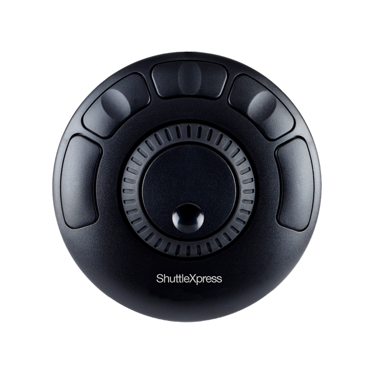
For the MACH system I find this one very handy and there are those who have it or the big brother working on LinuxCNC too.
Mine is the ShuttleXPress and others have the ShuttlePro
Shuttle Xpress - Multimedia Controller for Editors
Shuttle Xpress is the compact version of multi-media controller, Multimedia Controller PRO v2. Portable, lightweight and cost effective
 contourdesign.com
I can select an axis and move up to full speed or slower or turn the smaller dial one increment at a time. Very handy with MACH3 and I have buttons for spindle ON/OFF.
For Linux the biggest problem I've had with the pendant was the way I store it. Magnets on the back hold it onto the mill. I just reach over and press it and it stays. But... one time I was sloppy and I dropped it. On the way out of my hand my fingers spun the knob. The selection switch was still set on an axis and sure enough it ran the table into a tool bit I think. Don't remember what I broke or how expensive it was. Now before I set it down I switch off the axis selection. Much safer.
Overall what I like about the ShuttleXpress is it sits flat and very easy to move the axis. No need to rotate a switch to select the axis. Just tap X through A and turn the wheel.
Years ago for MACH I bought a MODIO board from Australia. I never made it that far but a friend connected up a keypad and LCD display to it and used it as a pendant. MACH and LinuxCNC both support MODBUS. Easier than running a bundle of wires from the MESA if it's a movable pendant.
I'll dig out my CAN bus interface and post that in a separate reply.
The Pendant for the LinuxCNC system can have the buttons defined to do whatever you want.
[XHC-HB04]
BUTTON=01:button-goto-zero
BUTTON=02:button-start-pause
BUTTON=03:button-rewind
BUTTON=04:button-probe-z
BUTTON=05:button-macro-3
BUTTON=06:button-half
BUTTON=07:button-zero
BUTTON=08:button-safe-z
BUTTON=09:button-home
BUTTON=0A:button-macro-1
BUTTON=0B:button-macro-2
BUTTON=0C:button-spindle
BUTTON=0D:button-step
BUTTON=0E:button-mode
BUTTON=0F:button-macro-6
BUTTON=10:button-macro-7
BUTTON=16:button-stop
BUTTON=17:button-reset
The above is gibberish of course unless you understand the whole HAL/INI file concept in LinuxCNC but the file pulled into the INI file to work with this pendant is xhc-hb04.tcl The tcl file is text and Tickle/TK
[HAL]
HALUI = halui
HALFILE = G3616-MESA-7i92.hal
HALFILE = custom.hal
HALFILE = LIB:xhc-hb04.tcl
POSTGUI_HALFILE = postgui_call_list.hal
SHUTDOWN = shutdown.hal
And so on. When I don't look at it for a year I forget how to do everything. I've attached a zip with my CANopen stuff for Mist control and Drawbar.
Attachments
slow-poke
Ultra Member
John,
Thanks, much appreciated. Initially the HAL ini file aspect looked a little cryptic but now that I'm tweaking it I really like the way it works and appreciate the customization flexibility it provides.
Rough plan is to mount the button and knob PCB perhaps on the front of the pulley cover, need to think about that. The pedant concept (although convenient) just seems like an accident waiting to happen, I would drop it at some point. On my old mill I had a big red E-Stop button on the UI board that would get hammered from time to time, and I never had to wonder where it was, more like muscle memory reaction.
Jeff
I wired in the original ESTOP and added one to the front of the cabinet in series with the first. It goes into the BoB which passes it on the PC while instantly eliminating step pulses and outputs. An intelligent BoB has both advantages and disadvantages.John,
Thanks, much appreciated. Initially the HAL ini file aspect looked a little cryptic but now that I'm tweaking it I really like the way it works and appreciate the customization flexibility it provides.
Rough plan is to mount the button and knob PCB perhaps on the front of the pulley cover, need to think about that. The pedant concept (although convenient) just seems like an accident waiting to happen, I would drop it at some point. On my old mill I had a big red E-Stop button on the UI board that would get hammered from time to time, and I never had to wonder where it was, more like muscle memory reaction.
Jeff
The thing about a pendant is you can hang onto it while standing at odd angles to the machine and jogging up to a point 0.0001" at a click so to speak with the MPG.
slow-poke
Ultra Member
Keyed the end of the new shaft for the original bevel gear, so manual operation with the hand crank will still be an option. Made the little sleeve (that will need to be shortened slightly) after final fit. Original shaft in bearing area was 19.92mm (a tiny bit sloppy), new shaft was turned to 19.98mm slightly better bit. The new big gear gets mounted to the flange. Depending on what final large timing gear I find, mating it to either this sleeve or a new one if necessary provides more gear mounting options. Apparently some Subaru overhead 8m cam gears appear to be about the right size. Plenty of half disassembled Subaru engines on facebook;-)


I'm a bit confused. It looks like your ball nut is mounted right on the base of the mill but on an earlier shot it looked like the lead screw nut was mounted on a pillar. Can you take a photo of the entire mill. I'm having trouble visualizing where the lead screw goes as the knee goes downwards.
slow-poke
Ultra Member
John,I'm a bit confused. It looks like your ball nut is mounted right on the base of the mill but on an earlier shot it looked like the lead screw nut was mounted on a pillar. Can you take a photo of the entire mill. I'm having trouble visualizing where the lead screw goes as the knee goes downwards.
The ballscrew goes down into the cavity of the base just like the original leadscrew did, with the knee all the way down, the end of the ballscrew will be at floor level. The base in the previous image will be replaced with a slightly raised version when I settle on the final timing pulleys.
Ah. It's just that normally the ACME nut is raised on a post to keep swarf and coolant off it. The knee can't go all the way down anyway because of the sides of the assembly so when the knee is at the bottom most point there's still space from that bottom area to the drive gear on the knee.
slow-poke
Ultra Member
Update:
Mechanical aspects of CNC conversion are now complete. All axis closed loop using linear scales for feedback and actual vs. commanded errors are less than 0.001" fast and quiet. The knee is not as quiet as the others because of the belt drive but still really fast and quiet compared to steppers. I ran the knee at 150 IPM effortlessly. I'm sure it will go faster, but it's fast enough for me. The knee handle is in a big box with all the other non required stuff;-)
Next up, the fun stuff, I'm going to dream up a fancy control board with lot's of push-buttons. IMHO mouse clicks are for PC's not machines.
So exciting. And yes 150 IPM on the knee is scary fast.
I forget. Which CNC system are you using?Update:
Next up, the fun stuff, I'm going to dream up a fancy control board with lot's of push-buttons. IMHO mouse clicks are for PC's not machines.
slow-poke
Ultra Member
LinuxCNC.
Free and works great. I love the way you can customize if desired. I'm not sure what other software lets you close the loop with linear scales to eliminate bearing, ballscrew and temperature errors?
My initial thought was that Linux would require a lot of specialized "Linux" knowledge but my experience is that it's actually a lot like Windows, without the; bloat, spyware and countless bugs and upgrades. It just works!
My old Mach setup even with backlash compensation was often out 0.002-0.003. No longer an issue.
Last edited: