-
Scam Alert. Members are reminded to NOT send money to buy anything. Don't buy things remote and have it shipped - go get it yourself, pay in person, and take your equipment with you. Scammers have burned people on this forum. Urgency, secrecy, excuses, selling for friend, newish members, FUD, are RED FLAGS. A video conference call is not adequate assurance. Face to face interactions are required. Please report suspicions to the forum admins. Stay Safe - anyone can get scammed.
-
Several Regions have held meetups already, but others are being planned or are evaluating the interest. The Calgary Area Meetup is set for Saturday July 12th at 10am. The signup thread is here! Arbutus has also explored interest in a Fraser Valley meetup but it seems members either missed his thread or had other plans. Let him know if you are interested in a meetup later in the year by posting here! Slowpoke is trying to pull together an Ottawa area meetup later this summer. No date has been selected yet, so let him know if you are interested here! We are not aware of any other meetups being planned this year. If you are interested in doing something in your area, let everyone know and make it happen! Meetups are a great way to make new machining friends and get hands on help in your area. Don’t be shy, sign up and come, or plan your own meetup!
You are using an out of date browser. It may not display this or other websites correctly.
You should upgrade or use an alternative browser.
You should upgrade or use an alternative browser.
ThirtyOne Driver's projects
- Thread starter ThirtyOneDriver
- Start date
ThirtyOneDriver
Johnathan (John)
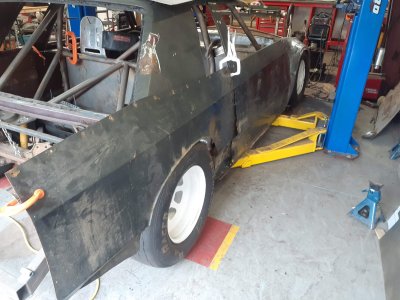
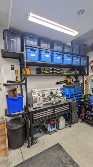
The ice racing car is finally out of the shop and I now have my third bay back - I need to do some major shuffling of things around while I have the space.
Next big goal is to build the stand for the lathe. Unfortunately, I missed the sale on the tool boxes I was originally planning for so I need to amend my plans slightly/do without tool storage for the time being.
What's "too high" for a lathe center height? 48"... 50"? I'm 5'11" (71") and don't enjoy being stooped over. Feed handles are ~10" below the lathe center height. Standing straight up w/ my elbow bent at 90°, my hand is at a 39" height.
My lathe centerline height is 46" off the cement floor. But I made a wooden platform, (for height, but also for comfort, anti-fatigue) for me to sand on which is about 4.5" tall. This height works pretty well for me, I'm 5'7". With a slight bend at the waist I can look directly down onto the tool bit. So make sure you take a platform in consideration before you make your lathe stand.
I'm not sure that is a good idea. To use it to its best, the lathe needs to levelled and aligned. Putting it on tool chests may not be a very solid way to do that. I guess it would depend on how rigid the tool chests are and of course you would have to take the wheels off.I'm thinking of putting two of these under the lathe instead - rough planning puts the Lathe Center Height at about 38". I think that should be fine as I've been building my workbenches for 38-43" for more than a decade.
ThirtyOneDriver
Johnathan (John)
Definitely would take the wheels off... the tool boxes would slide into a 2" x 2" x 0.100" frame that will be built to support and level the lathe (leveling feet). With the intent of putting the lathe and milling machine side-by-side, the extra machining related tools would have somewhere to go. I currently have three tool boxes too many on the shop floor and any of them (+ the 2x2 frame to support the lathe, the 2x2 frame to support the toolbox(es), and space for levelling feet) would put the lathe center height just too high.I'm not sure that is a good idea. To use it to its best, the lathe needs to levelled and aligned. Putting it on tool chests may not be a very solid way to do that. I guess it would depend on how rigid the tool chests are and of course you would have to take the wheels off.
I think there's a Kitchener member that did similar to what I would like to do - I've got to run so I won't be able to look for his post until late this morning.
Definitely would take the wheels off... the tool boxes would slide into a 2" x 2" x 0.100" frame that will be built to support and level the lathe (leveling feet). With the intent of putting the lathe and milling machine side-by-side, the extra machining related tools would have somewhere to go. I currently have three tool boxes too many on the shop floor and any of them (+ the 2x2 frame to support the lathe, the 2x2 frame to support the toolbox(es), and space for levelling feet) would put the lathe center height just too high.
I think there's a Kitchener member that did similar to what I would like to do - I've got to run so I won't be able to look for his post until late this morning.
I dunno how your lathe is levelled. Best to read your manual or get input from a machinist who owns that same lathe or a similar one.
Mine has 6 levelling feet one on each outboard corner of the lathe itself and two at the joint between the head and the bed. It's these two center levelling feet that get forgotten or improperly adjusted.
While some may disagree, I believe the levelling process is much more about aligning the spindle with the bed and making sure that the bed is not twisted than it is about actual levelling. For most lathes, this requires three pairs of levelling feet and a very meticulous alignment process.
ThirtyOneDriver
Johnathan (John)
Similar to this one... but add-in a center set of feet/support.
My lathe sits directly on the Busy Bee stands; the stands have spots to put levelling feet in but I haven't done it yet.
The planning process around this project is aimed at the tool storage portion of the solution although I intend on taking steps to ensure that the lathe can be levelled/aligned (as part of the process/planning) when it's installed.
(photo courtesy of @SomeGuy and his project)
Attachments
ThirtyOneDriver
Johnathan (John)
Considering these - the Craftsman is only 12" deep but I could build a frame/stand large enough to put a pair side-by-side; the Mastercraft is wide enough that I wouldn't do that. Craftsman is taller (27.xx" vs. 21.xx").
The flip up tops would be removed at the hinge and what would be used as the top tool storage area would be open to access (I would place the tool box in the bench lower than the top crossmember).
The flip up tops would be removed at the hinge and what would be used as the top tool storage area would be open to access (I would place the tool box in the bench lower than the top crossmember).
Attachments


My lathe sits directly on the Busy Bee stands; the stands have spots to put levelling feet in but I haven't done it yet.
I downloaded the manual for your lathe and had a good look.
It appears that there is no convenient way to align the spindle with the bed. About all you can do is take any twist out. I suppose if you tested it and found that it was way out you could use shims.
In any event, the bed appears to be a one piece affair with just four bolts to tie it down to the stand - one at each corner.
As long as your stand is stiff and sturdy it will probably be better that the original stand.
Can you take your chip tray off and use it with your new stand?
SomeGuy
Hobbyist
Similar to this one... but add-in a center set of feet/support.
My lathe sits directly on the Busy Bee stands; the stands have spots to put levelling feet in but I haven't done it yet.
The planning process around this project is aimed at the tool storage portion of the solution although I intend on taking steps to ensure that the lathe can be levelled/aligned (as part of the process/planning) when it's installed.
(photo courtesy of @SomeGuy and his project)
I highly doubt a center support would have done anything with my stand. I haven't done the math, but I suspect you could sit a few thousand pounds dead center on this thing with almost zero deflection.
When it comes to leveling, I've leveled the stand itself in space but the second step would be shims under the 6 bolts that hold the lathe to the top to get it bang on accurate.
ThirtyOneDriver
Johnathan (John)
Yes @Susquatch the chip tray can be removed and reused on the "new" stand.
Didn't intend on saying your stand needed the center legs @SomeGuy - I was just referencing the build and what my plan was.
I'm off to Lowes to pick up a couple of tool boxes before I lose out on another sale...
Didn't intend on saying your stand needed the center legs @SomeGuy - I was just referencing the build and what my plan was.
I'm off to Lowes to pick up a couple of tool boxes before I lose out on another sale...
I highly doubt a center support would have done anything with my stand. I haven't done the math, but I suspect you could sit a few thousand pounds dead center on this thing with almost zero deflection.
When it comes to leveling, I've leveled the stand itself in space but the second step would be shims under the 6 bolts that hold the lathe to the top to get it bang on accurate.
Frankly, I think you would be shocked to discover how much several thousand pounds would distort your lathe and your stand......
That said, I doubt your lathe will ever see several thousand pounds. At most a hundred pounds or so.
We tend to think of big steel or cast iron things as though they are the rock of Gibraltar. But they obey the simple laws of science just like everything else. Any force, no matter how small, will distort any metal, no matter how big, to some degree. It isn't if, it's only how much. For most applications it isn't enough to worry about!
I'm not inclined to worry about @ThirtyOneDriver s lathe given that there is no practical way to align it anyway.
If yours has 6 Bolts, and you do any significant precision work, it might be worth doing though. If nothing else, it would be good to know how much it is out (if any).
I downloaded the manual for your lathe and had a good look.
It appears that there is no convenient way to align the spindle with the bed. About all you can do is take any twist out. I suppose if you tested it and found that it was way out you could use shims.
I cant say for sure but this topic arises a lot. The CX709 manual doesn't make reference to headstock adjustability, but that could be a function of the document shortcomings, not the machine. Most of the Asian lathes with attached headstocks have set screws or similar to set the HS casting yaw & thus spindle alignment to bed. That's supposed to be dialed in when it leaves the factory., but nothing saying it cant go out of adjustment. Sometimes the adjusting screws are omitted on the documents, sometimes they just show as a spec of fly sh*t with no reference. Best to have a look at the machine. You'll typically find them in the most inaccessible locations LOL. Beware - loosening & breathing on them is enough to displace the spindle. And before commencing you need to have an appropriate test bar to see what you are doing. And yes, a tiny headstock/spindle misalignment typically trumps lathe bed twist by a long shot, so this needs to be verified first. If your HS is pointing out 1-deg & the bed is compensate twisted in 1-deg, you now have 2 competing issues instead of zero. For machines with integrally cast headstock/lathe bed, this HS adjustment option isn't available, which is probably where most of the well intended but incorrect advice comes from. In that case, adjusting lathe twist (loosely called levelling) is the only card to play. Levelling is a bad term in this application. There is little harm running a lathe slightly non-level. Twist is another matter.
Attachments
SomeGuy
Hobbyist
Frankly, I think you would be shocked to discover how much several thousand pounds would distort your lathe and your stand......
That said, I doubt your lathe will ever see several thousand pounds. At most a hundred pounds or so.
We tend to think of big steel or cast iron things as though they are the rock of Gibraltar. But they obey the simple laws of science just like everything else. Any force, no matter how small, will distort any metal, no matter how big, to some degree. It isn't if, it's only how much. For most applications it isn't enough to worry about!
I'm not inclined to worry about @ThirtyOneDriver s lathe given that there is no practical way to align it anyway.
If yours has 6 Bolts, and you do any significant precision work, it might be worth doing though. If nothing else, it would be good to know how much it is out (if any).
There's no doubt it would move things, heck, there was bounce when I was carrying the 24 foot long sticks of 2" tube I used...but as a structure, it's stiff.
Just using some simple deflection calculators, a couple thousand pounds on center point should only deflect about 15 thou, but that's not taking into account any of the structure (I have some triangulation in the back for instance) so it's likely less.
With a 500lb hobby machine, there's diminishing returns in trying to make an insane structure. If I had gone thicker tube or another cross piece or filled the tubes with concrete, would I get a better finished part or would it be easier to make? Probably not, the lathe itself (spindle bearings, tool post deflection, how flat the ways are, etc.) would play a bigger role.
That sounds more reasonable to me. Except I wouldn't call 15 thou "only 15 thou". LOL!
I totally agree with your value proposition. It's just not worth going crazy over.
ThirtyOneDriver
Johnathan (John)
Speaking of value... those Craftsman toolboxes I picked up for $140 ea aren't anything to write home about, but I think they'll get the job done.
@PeterT - I'll try to take a better look when I have a chance... IIRC the CX709 manual references the source company in the first para. - hopefully I can turn that into a better set of instructions and if not I'll have more questions (I'll try to have photos when I ask them).
@PeterT - I'll try to take a better look when I have a chance... IIRC the CX709 manual references the source company in the first para. - hopefully I can turn that into a better set of instructions and if not I'll have more questions (I'll try to have photos when I ask them).
IIRC the CX709 manual references the source company in the first para. - hopefully I can turn that into a better set of instructions and if not I'll have more questions (I'll try to have photos when I ask them).
Yup, top of page 3 says:
"BL330E PRECISION GEAR HEAD LATHE As part of the growing line of metalworking equipment, we are proud to offer the BL330E Metal Lathe. The name guarantees ANHUI PAN-SINO. By following the instructions and procedures laid out in this owner’s manual, you will receive years of excellent service and satisfaction. The BL330E is a professional tool and like all power tools, proper care and safety procedures should be adhered to."
Since the manual directly calls out the lathe maker, I'm not sure you will find better instructions elsewhere. These are probably the makers own instructions. But worth a shot anyway!
ThirtyOneDriver
Johnathan (John)
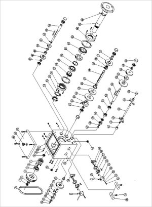
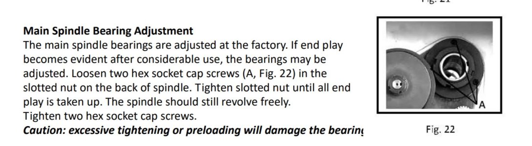
I went through a bunch of different instructions for it and you're correct @Susquatch, those are the "best" ones although I think that BB dropped a couple of pages off the back that are helpful (diagrams and parts lists for tail stock among other things). The closest thing I could find to adjusting the headstock was this little blurb.
Attachments
ThirtyOneDriver
Johnathan (John)
Welding
Carry over from the Classifieds where I was contemplating selling my Precision TIG 225 (Lincoln Electric, almost everything in my shop related to welding is LE due to a past relationship w/ the company) (https://canadianhobbymetalworkers.c...precision-tig-welding-machine.4654/post-65795).
I need a MIG - I'm returning my long-term loaners (a pair of the retail 180 MIG) to their owners. The 180C, 256 and 260 are on my short list; I'm heavily favouring the 260 but haven't made a decision/commitment yet.
Machining
I got some practice on both machines. There's a chance that I have previously bent the spindle and will be trying the tramming/squaring methods previously discussed here when I have a chance to sit down and give that my full attention/concentration. When I do that, I'll need to figure out if I created a problem in the past when something jammed really violently (before I was a member of this group, when I was first 'trying' things) or if the table is truly not square to the head.
How'd I get that notion? The end mill I was using this past weekend seemed to have a shake/imbalance to it - both the end mill and the collet were new, unused and I know I jammed the machine hard enough that I already had concerns. I'll have someone with more experience look at it when they have an opportunity to confirm my suspicions/diagnosis.
Projects Overall
With the absence of the ice-racing car, I've been focusing on organization, cleaning and other housekeeping. I've completed small projects that develop/freshen skills while using materials I already have and create 'homes' for tools and objects. The machining stuff has been transferred into the Craftsman tool boxes I bought last week, I repaired a MIG 180T (new control board, freshened everything up and got it ready to return to my Dad, so... tip-top shape), freshened the other 180T and packed it up for my buddy (as well as his 175 Squarewave he brought by for practice/lessons), diagnosed a bad bottle of Argon and switched it out, relocated and freshened my 225 TIG, built some brackets... etc. etc. etc. Now that I have heat, it's been easier to put in more hours even if they're not fully productive hours. "Piddling" still gets stuff put away and better organized.
Current short list: lathe center height reference gauge (@Susquatch designated project), lathe QCTP mounting bolt, 2"x2" frame/stand for lathe and Craftsman tool boxes, much more "piddling" ... text that just came in may prioritize moving my chassis jig and whatever I need to modify on it to facilitate that... sounds like my chassis is ready to be delivered.
ThirtyOneDriver
Johnathan (John)
Had a hand determining if I bent the spindle today and the dial indicator result determined that the spindle is straight.
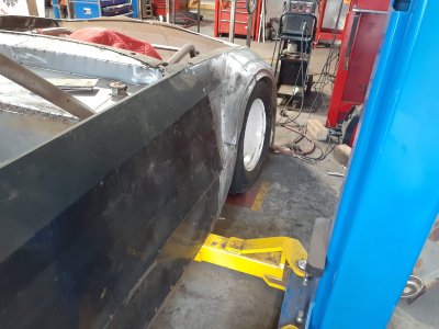
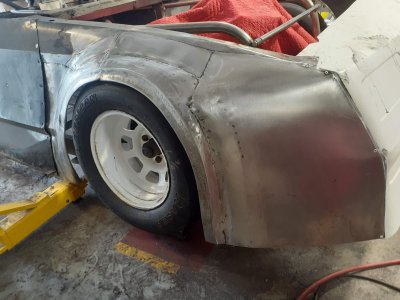
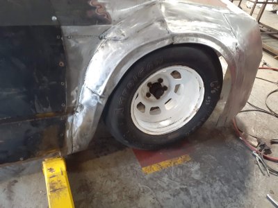
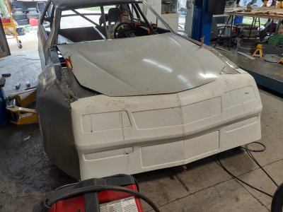
Set-up and tried the english wheel in the late afternoon (small Craftex one) and found it pretty interesting. The setup I have may be good enough for fenders that I've been bead rolling, piecing together, and hammer and dolly forming in the past.
Before anyone picks on the craftsmanship of certain parts of that car - the owner did a bunch of work before giving up on it and dropping it off and I wasn't going to redo certain parts of it. Also, keep in mind that the body/fender is likely to look good only until the driver hits his first car... this guy typically does that before the green flag flies.