• Scam Alert. Members are reminded to NOT send money to buy anything. Don't buy things remote and have it shipped - go get it yourself, pay in person, and take your equipment with you. Scammers have burned people on this forum. Urgency, secrecy, excuses, selling for friend, newish members, FUD, are RED FLAGS. A video conference call is not adequate assurance. Face to face interactions are required. Please report suspicions to the forum admins. Stay Safe - anyone can get scammed.

The Taylor monoplane saga - propeller hub build & other things

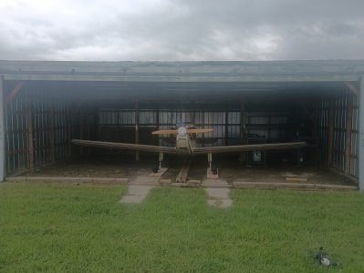
well hangar might be a stretch, its more of a shed that's big enough for a small airplane
A roof is a roof, there is always free paving stones and stuff around from someone doing a yard reno, cheap flooring.

Good to see more of the bird in the air. Next year will be the flight plan for Chestermere International.

One exercise I used to do in the Luscombe was to set the throttle to 1800 and slowly pull back on the stick and see how high the nose would go before she tumbled. Dad and I would make a competition out of it. lol
 
A roof is a roof, there is always free paving stones and stuff around from someone doing a yard reno, cheap flooring.

Good to see more of the bird in the air. Next year will be the flight plan for Chestermere International.

One exercise I used to do in the Luscombe was to set the throttle to 1800 and slowly pull back on the stick and see how high the nose would go before she tumbled. Dad and I would make a competition out of it. lol

yep for sure, im not sure how long the situation will last, Chestermere is right there, it may get gobbled up in the next few years and then i will have to move. It will work for now while i save some bucks to put up my own shed big enough for an airplane

i was pretty surprised how high the nose went before it tumbled on the mono, it indicated 20mph, which cant be accurate (speed wise), but it indicates 20 every time, so even though i dont think that airspeed is correct, it is consistent, and i know where the line is so to speak. I also thought of the possibility that because it only idles down to 800-1000rpm, combined with the bigger prop, i may be getting some thrust, and its not really a true power off stall
 
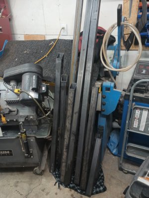
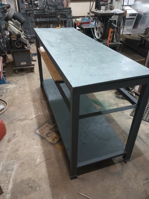
The weather was questionable for a third flight today figured I would make a second identical work bench for the hangar, i still had a partial stick of that 2x2 hss 1.5 angle so you know....I did have to buy 1 more stick of 2x2hss and 1.5 angle (i ordered it previously in the week)

I Thought i should take some photos this time

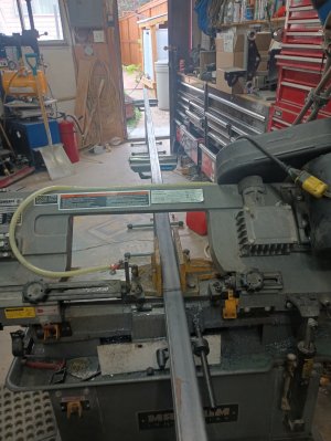
Cutting it up, and the stack of cut pieces ready to go
IMG_20250718_175825446_HDR.jpgIMG_20250718_181910614.jpg

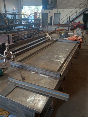
Took a trip to the shop of my main contractor, i don't have a table large enough or a flat enough spot on the floor, there are ways to do it with stands....but for what its worth might as well head over to the shop

IMG_20250719_110043921_HDR.jpgIMG_20250719_111854026.jpg

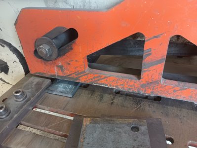
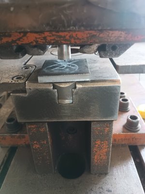
Ironworker is great for rough stuff like the foot plates, chunk up the lengths on the shear, and pop the 11/16 holes using the punch
IMG_20250719_112456993.jpgIMG_20250719_113000134.jpg

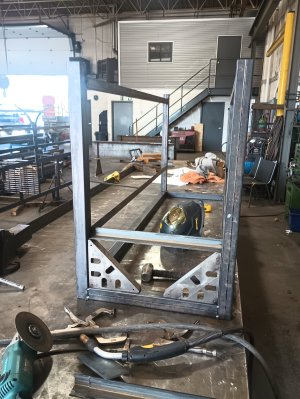
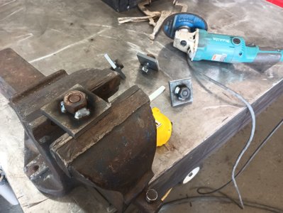
Welding nuts in for the adjustable feet, using 5/8 structural bolts, because there is a big bin that no one will ever use. Yea there is no guard on that grinder, it's one of the shop guys, not mine, I hate running them without guards (modified that is) for various reasons

IMG_20250719_113504985.jpg

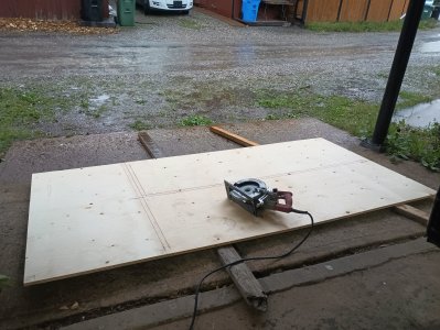
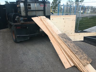
made it to home depot before tonight's monsoon for a sheet of plywood, cutting it up under the overhang i built in another thread, hurray for that!
IMG_20250719_200958871.jpg

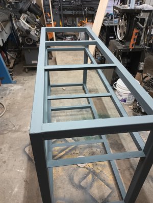
Welded out, painted, it looks a lot bigger in the garage than in the shop or at the hangar, funny how that works. Ran out of paint, so for now the intermediate shelf gets nothing, and im going to scavenge for the chunk of 5/8 to fill out that hole (in both benches)

IMG_20250719_202504643.jpgIMG_20250719_210415845.jpg

total material for the 2 benches (including the left over, but new, i already had), 2 1/2 lengths of 2x2 (at 40$/pc), 4 lengths of 1.5 angle (25$/pc), 2 sheets of plywood (50$/pc), and 1 qt of paint (40$), total of 340$, I still need to screw the tops down, so lets add 10$ for that, 350$, or 175$ for each bench. I probably could have bought something for around that cost each, but i don't think they would be very stiff (important for the gravel floor), and probably not last as long

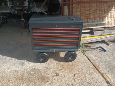
And scored this little cart at princess auto for 35$ and the tool box on marketplace for 200, I think its time to stop spending money on hangar stuff for a bit

IMG_20250717_174851428.jpg
 
Wow, I've seen flimsier lathe stands LOL. Looks great. What did you end up selecting for metal paint (and primer if that preceded it). How did you mount the ply top to the frame (if replacement comes one day).

One idea I've brain filed is a framed table top with open cells. Costs another sheet of plywood but you can pack a lot of stuff in there. This is the general idea, more popular with the wood guys for some reason. Doesn't have to be those rounded aircraft spar look.
1752989745554.png
 
Wow, I've seen flimsier lathe stands LOL. Looks great. What did you end up selecting for metal paint (and primer if that preceded it). How did you mount the ply top to the frame (if replacement comes one day).

One idea I've brain filed is a framed table top with open cells. Costs another sheet of plywood but you can pack a lot of stuff in there. This is the general idea, more popular with the wood guys for some reason. Doesn't have to be those rounded aircraft spar look.
View attachment 67515

I have seen a bench like that on a house site before! it was super cool, it was either trim carpenters or cabinet guys who had built it, i don't recall. The guy was very excited to tell me about it when I commented on it. I think the rounded spar looking holes are somewhat a matter of pride in workmanship, and it adds some form to the function of the table.

For the paint i just used tremclad, its easy to get, and with some prep it does seem to hold up reasonably well. I did scuff it up with a red scotch brite and use wax and grease remover before hand. No primer, just paint, more for looks than anything else.

I was planning on using countersunk self drilling or if i cant find any of those i will go with countersunk self threading screws right into the hss frame and cross members, nothing to crazy.
 
I was planning on using countersunk self drilling or if i cant find any of those i will go with countersunk self threading screws right into the hss frame and cross members, nothing to crazy.

Or maybe pre-drill the holes in the frame & screw it from the underside. Probably same end result but might be easier if you ever flip it over one day or change your mind & replace it.

I am still TIG-less but I was thinking about this aspect for a future bench - how to integrate a metal welding plate on a portion of the table top so the entire thing doesn't have to be a big, heavy, expensive 'all metal' plate top like a welding/fixture table. The trouble is matching the height of say 5/8 or 7/8 or whatever plywood thickness. I suspect welding tables are heavy duty for a reason especially for fixturing slots/holes. Maybe trying to combine this functionality with a workbench is not a good idea especially with a wood top on one side? I thought about a metal plate mounted on little legs or tube frame you just drag out for welding & put away again. Seen any ideas on this front?
 
Or maybe pre-drill the holes in the frame & screw it from the underside. Probably same end result but might be easier if you ever flip it over one day or change your mind & replace it.

I am still TIG-less but I was thinking about this aspect for a future bench - how to integrate a metal welding plate on a portion of the table top so the entire thing doesn't have to be a big, heavy, expensive 'all metal' plate top like a welding/fixture table. The trouble is matching the height of say 5/8 or 7/8 or whatever plywood thickness. I suspect welding tables are heavy duty for a reason especially for fixturing slots/holes. Maybe trying to combine this functionality with a workbench is not a good idea especially with a wood top on one side? I thought about a metal plate mounted on little legs or tube frame you just drag out for welding & put away again. Seen any ideas on this front?

I suspect the screws would pull out if i just went from the underside, its only 5/8 plywood, so might have 1/2" into the plywood, i found some wafer head self tappers, ill give that a go

there are lots of ways to build a welding table, if you wanted to have plywood on one side and steel on the other it would be as easy as shimming the plate up with flat bar, 5/8 ply on one side, 1/4 plate with 3/8 flat bar on your supports to shim it up. 3/4 ply 1/4 plate and 1/2" flat bar, etc etc. Mig or stick you would end up with little burn marks from the sparks and spatter, but i wouldn't be concerned about a fire, it takes quite a bit to get plywood going.

Most shop welding tables dont have slots or holes for fixturing, just a chunk of plate on a frame of some sort, normally at least 3/8 thick, ideally 1/2+, the constant tacking of tabs and other things to the tables warps the top other wise. Many things are also built on the floor or horses, you will never have a big enough table, thats just reality.

I have yet to see a fixturing table "in the wild", im sure in some very high end shops that do lots of one off expensive fabrication (Bikes, bicycles, aerospace, etc) probably employ them, but its not something ive seen, so not really something you have to have, but nice to have for sure.

How heavy you build your table is totally up to you, the advantage to a big thick piece of plate is that it is already quite flat and requires minimal framing, and will likely stay flat, but it is big, heavy and expensive. If you just plan to use it more as a ground plane, then just about anything will work, a chunk of 10g with some framing would serve in a hobby shop for many years, it wont be as flat and sturdy as a piece of 1/2", but it would be 1/5the weight, and probably 1/4 the cost. So look at your budget, what you realistically want out of the table, and go from there, lots of ways to skin that cat.
 
One idea I've brain filed is a framed table top with open cells. Costs another sheet of plywood but you can pack a lot of stuff in there.
That's a torsion box bench. Generally a plywood top and bottom that sandwich a vertical square grid making a very sturdy and flat work surface. Handy storage too.
 
That's a torsion box bench. Generally a plywood top and bottom that sandwich a vertical square grid making a very sturdy and flat work surface. Handy storage too.

Yup, my own shop tables are made that way. This is the smaller one when I upgraded to a bank of Ikea drawer units. When I built the top I didn't think to open up the side rails for storage. Thinking about this some more, there probably is something about cutting cell openings, leaving some top & bottom meat to maintain rigidity like the fully enclosed peripheral plywood provides.

1753062180331.png
 
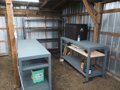
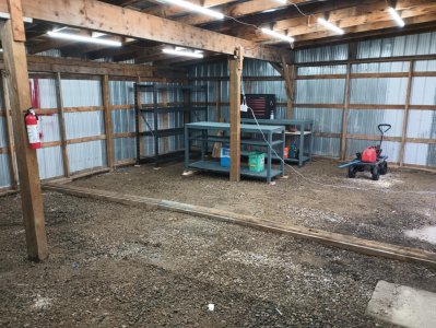
starting to look like a little workshop over in the corner, I think next up is a couple of "duck boards" for between the benches and in front of the shelving and ill have to keep an eye on marketplace for a few shop tools, bench grinder, vise, drill press, etc, that'll round things out

240w of led lighting seems to be enough, i think i will still need some task lighting, once monsoon season finished up here i will hopefully get the little taylor moved over to its new home, that should give me a better idea of what lighting is still required

235f0069-eadb-4230-9521-2a657736fb61.jpg3b0301f0-8540-4744-9882-a813405da4e8.jpg
 
Where's the fun in that ?
The fun is you keep trying to control the airplane and as the nose rises and the airplane slows and slows and slows until it literally snaps at the top and you spin out of it. Keep in mind that the rpm is 1800 the whole time so when it snaps over the top it really snaps, WAHOO. 😀😀
 
Canada Post must be trying to set some records! it's just Edmonton to Calgary, but even that normally takes 2 days at least !

Thanks again @John Conroy

View attachment 51384
FYI, USPS "changed" a couple years ago, to "cut out $$$$ expenditures", So, a Eugene Oregon letter, Package Any Mail, TO EUGENE Oregon travels 100+ Miles NORTH to Portland to "get Sorted" To then Return to EUGENE: THREE DAYS, to go Three Miles, honest I can't make up crazier stories!!!!

philip from the Great Pacific NorthWET, Oregon USA
• • • • • • • • • • • "(The) rights of some will be eliminated • • • • • • •
• • • • • • • • • • by the neurotic “feelings” of others".
~ Mark W. Smith35
 
had a break in the weather and flew the mono over to chestermere today, finally in its new home, out of the sun, rain and snow

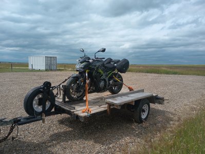
That short little 30-40 minute move took a full 8 hours to complete, drive to Vulcan with the trailer (1h5m), fill up the plane, preflight, warm up, 2 circuits and off for the the 30 minute flight, with pattern entry 40 minutes total (for the x country, 20 minutes in the circuit at Vulcan) land, talk with people there until the wife shows up....talk some more, wife gets antsy...continue talking, oops! Haha. Eventually pack the bird away and 35 minute drive home, hop on the motor cycle cruise back down to Vulcan, talk to some guys on the ramp...(There does seem to be a pattern here), load up the bike, drive back to Calgary, unload the bike, unhook the trailer....5.30, started at 9am 😀

IMG_20250726_130045662.jpgIMG_20250726_155616364.jpg

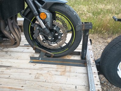
Made this little wheel chock for the trip... not really worth building at 120ish$, but I had the material and didn't want to spend the money for a likely 1 time use..it did work pretty well however, I'll have to squirrel it away some place

IMG_20250726_154304734.jpg

Now I get to unload the spare parts and tools from the truck into the hangar, it's been loaded up with all maner of airplane bits and tools for the last 3 months, don't want to forget something after driving an hour to vulcan...
 
Hangar is getting setup nicely, i kept the marketplace drill press at the house and moved the house drill press over to the hanger

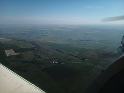
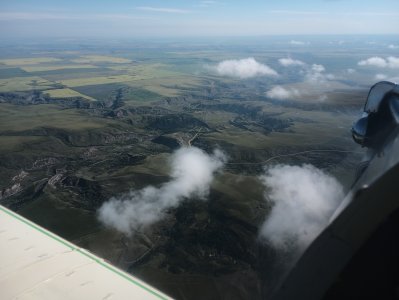
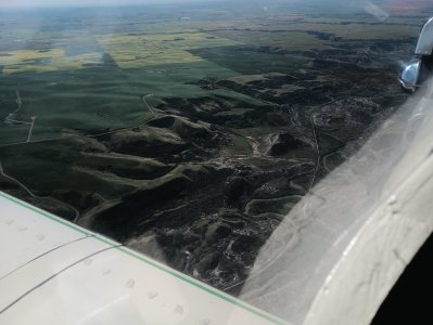
Made a hop over to Drumheller today before the storms....i swear this must be the rainiest year ive witnessed living here, at lest the T-mono has a house, couple pictures and a few videos. The badlands are pretty cool, im going to figure out a new insta mount for the mono, i cant quite capture how stellar the hoodoos/badlands look from the air with the current mount

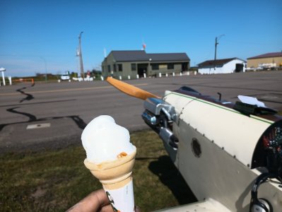
oh yea, free ice cream at Drumheller municipal!
IMG_20250804_103423255.jpg
IMG_20250804_094921122.jpgIMG_20250804_100631777.jpgIMG_20250804_111431393.jpg

the route, just a short flight, but the longest ive made in the T-mono, no oil consumption or leakage, I will need to drain the oil possibly before the next flight and look for metal, but with 5 hours on it now i think it would have locked up if it were making metal

route.jpg

I forgot to turn the insta on for the leg out, but this time i did remember to turn it on for the way back! getting the prop starting procedure figured out, 1 blade and she went, both times. Im thinking of a better spot for the insta....


The approach and landing, i still havent gotten the landing quite nailed yet, getting there. I did overshoot the base/final turn, i was lining up on the wrong field, again, my eye just wants to go to that field with the dark rows just to the west of the actual runway


And a 360 of the hangar, you can see the benches ive built in another thread, its coming along


Video skills are still a work in progress
 
Been plugging away at the distributor upgrade, a billet HEI unit with adjustable advance (amount and ramp). Ive had this distributor/coil kicking around for about a year, but i didnt want to put it on as i don't have have enough faith in singular HEI, when hei fails that it, no spark. the solution i have decided to work towards is a dual pickup dual coil setup similar to what the corvair guys do using an msd 8210 coil joiner (which came with one of the corvair flight motors i bought, yey!) and a second pickup.

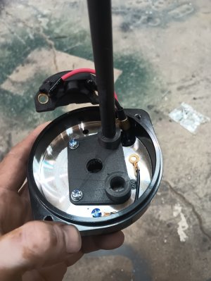
This is how the distributor comes, with a singular pickup/trigger, the plan is to put a second pickup opposite to the first , the trigger wheel has 4 lobes, so it should trigger the second pickup at 180 deg, the rotor will take care of sending the spark to the correct plug
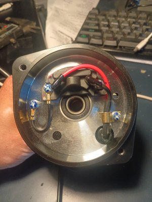
IMG_20250901_083954262.jpg

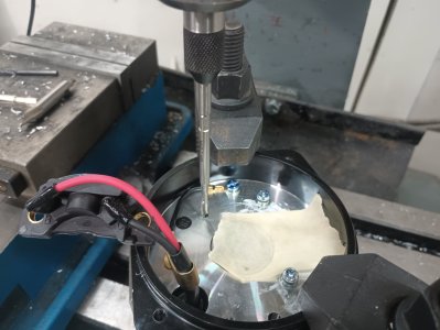
I did some measuring, made up a few pieces to check dimensions with the 3d printer, eventually getting to the point to make a drill guide for the second pickup using transfer punches. I was not sure how i could do this on the dro off the existing screw holes without the chance of monumentally screwing up. I figured the drill guide was probably best
IMG_20250901_182109440.jpg
drill and tap for m4 cap head bolts
IMG_20250901_184052372.jpg

Whoops, forgot to take pictures.....you can use your imagination, there is a second pickup opposite to the first pickup

The next step was some sort of test rig, I am confident that both pickups wont be exactly 100% 180 degrees apart, so i know there will be some difference in the amount of advance each pickup see's.....the question is really how much difference, i would be happy with less than 5 degree's and i would accept up to about 8 degrees, after all this is a backup, if the primary goes down (28 degree's) and i am left with 20 degrees of advance on the secondary that will still leave me with some thrust, hopefully enough to maintain level flight, or at least give me much more time to find a suitable field

...... side quest .....

Mid project, after printing a few pieces i was surfing amazon, looking at 3d printers.....my mis mash of printers has been triggering some ocd for a while now, ive wanted a pair, same part, same slicer settings, cleaner look......well the elegoo centauri carbon was on sale.....a day and a poor financial decision later i had a pair...ive made a new shelf since these photos....the ocd couldnt handle them on two different levels (necessitated by the miss mash that was there)......boy these things fly...the short video is printing a specialty transmission tool for one of the in-law's
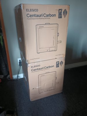
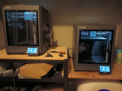
IMG_20250908_170817760.jpgIMG_20250909_213010693.jpg

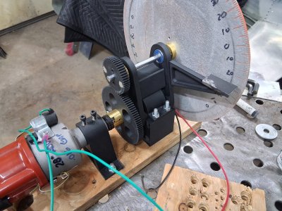
back to the main mission, here is what i have come up with, printed the gears, bearing holder (skateboard bearings), motor stand off and distributor mount with pla, the distributor gear and jackshaft ?blocks? out of brass on the late/mill and cut out and engraved the degree wheel on the printNC out of a scrap piece of 2mm aluminum. The spark plugs are installed in a scrap piece of aluminum flat bar tapped for m14x1.25 (standard plugs) with a m4 bolt tapped for the grounding wire that runs to the distributor and battery.

the blocks are threaded for set screws on to the motor shaft/jackshaft as well being tapped to bolt the gears on to the blocks

The jackshaft runs at 2x the distributor speed so that i can get accurate crankshaft degrees, i have a little bent wire to indicate TDC, without the cap and rotor i am able to get 3800rpm on the jackshaft using an optical tachometer, i need to have full advance by 3000rpm so thats plenty.
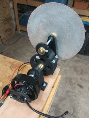
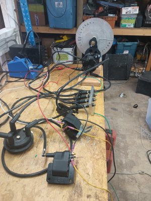
IMG_20250912_204920872.jpgIMG_20250914_161218560.jpg

Its hard to read the timing disc in the video, but they are firing about 3-4 degrees off from each other, i cant confirm the rpm, my optical tachometer is seemingly on the fritz, a friend has a standard automotive tachometer for me on Monday, but i believe i am getting full advance quick enough, i will confirm with the automotive tachometer when i get it


You may not see in the video but the spark looks much better with both coils running (it starts with one, then i turn the second on), hopefully this combined with what i hope is more consistent timing will give me a few more rpms on takeoff


There are a few more things to do, the secondary pickup is lacking heat paste and a dedicated ground, and i believe it is over heating as a result, The secondary does not turn back on every time unless i give it a few seconds.....more testing when the amazon fairy's drop off my tube of heat goop. The body of the disty does seem to get a bit on the warm side so it will also need some cooling air ducted, i imagine thats because the pickup/ignitors use the body of the disty as a heat sink.....and now there are two of them! Its not quite ready for flight, but proof of concept is there

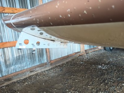
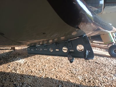
And a quick little airplane project....a new insta360 mount.....I want to try it out on a pole off the wing, see what those shots look like....but i dont want it to fall off....insta360's are expensive, and things falling off your airplane hitting other things is dangerous/expensive. This is out of a salvaged 1.2mm piece of aluminum, its uses some existing screws that hold the wing tips on as well as some 3m adhesive, the selfie stick (when i can find it) will clamp on using those two hose clamps. I have yet to fly with it to see what effects if any it has on handling as well as the video i get from it.
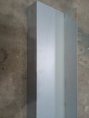
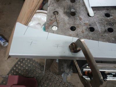
IMG_20250901_160437532.jpgIMG_20250901_161609515.jpgIMG_20250904_173526277.jpgIMG_20250904_173535445.jpg

And some plane videos because why not ? I bought a "gps remote", which allows you to turn on/off recording on up to 3 cameras (good because they have limited battery life) as well as giving the videos telemetry data

A friend was racing 125's on that weekend, I thought it might be neat to circle and see what kind of video i could get....apparently not that great...I was headed to brooks to see if i could see any storm carnage anyways so why not


I think the new camera mount might give me some neat videos on little flights like this (same trips as above)

 
well electronic distributor is a wash, i cant reliably start the plane via hand propping, it doesn't consistently fire at the same timing point with the low "cranking" rpm's, as well as firing at odd times when at rest....kinda scary. Bummer, especially after delaying flying due to a wicked chest flu.

before getting sick, I was with luck able to get it fired up (with luck and warm weather), tune the carburetor via Wideband o2 sensor, as well as do a few other little improvements, but back to points for the ignition i guess

I bought a new, higher quality, points distributor, which oddly enough wouldn't fire without sanding the points? strange, anyways, it had to go into the distributor test rig to check for total advance. 22 degree's, sort of? the distributor test rig was flexing under the torque required to spin the timing disc as well as the distributor. I wanted more advance anyhow, and to tune that in i would need to re-vamp the test rig to get a more stable indication of advance.

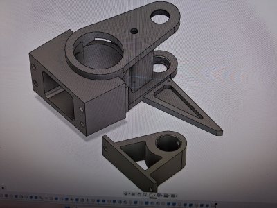
3D printer to the rescue again! These things are really great tools once you learn how to do modelling. The main problem with the original setup was that i made the bearing blocks bolt to the motor with adjustment for the gear mesh, it eventually began to torque over as the petg around the bolts wore. The new model does away with any adjustment and has 2 tabs that interface with the motor block to prevent any torquing over, i added a proper timing pointer, and made a new distributor holder with set screws to prevent the distributor from turning and skewing the timing. Send all the files over to the dual centurai carbons, and a few hours later i had a pile of new parts.

20251116_154459.jpg20251116_123454.jpg


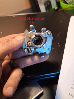
Here is the advance mechanism of the 009 distributor (my old 009), that little tab needs to be bent in/out to adjust total ignition timing, its a trial and error adjustment, check the timing, take off the cap/rotor, remove the points plate, bend the little tab, put everything back together, test again, over and over until you arrive at the total advance you want. I originally stopped when i had 28 degrees, it would probably start awesome, but i dont know how well it would idle and run firing at TDC until the advance kicked in, I decided that 25 degrees of advance with initial timing at 3 degrees would probably be better, they will hand start at 6 (with 22 of advance), but it can be a pita, im hoping 3 will be much easier.

advance.jpg
 
Back
Top