I’m always making something in the shop so I thought I’d open a window so people could peer in and see what mischief I’m up to.
Starting point:
I received a nice Vertex BS-01 dividing head and an equally nice 6” Burnerd 4 jaw chuck with my First mill. I also received a grotty looking 3 jaw mystery chuck with replaceable jaw inserts but it’s going to sit on a shelf for a while longer, this posting is about a backing plate to join the Vertex & Burnerd but it will also accommodate the mystery chuck.
The big undiscovered country in this for me was cutting the 1-1/8 – 12 internal thread that would be needed to fit the Vertex. I got some good advice from members a while back and I was left with a suggestion, show how I did it because there was a little twist that’s apparently unusual for threading.
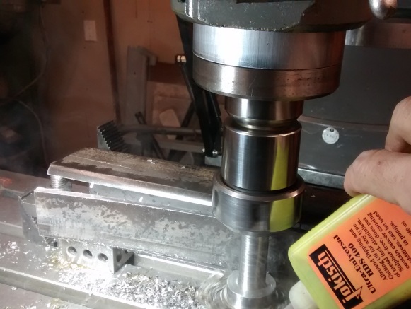
I prepped the rough HRS round stock on the mill and laid out the critical hole positions before digging into the internal threads. I was very conservative about the threading operation and I chose to use a hand crank to do the turning. This is one of the tricks the UK Myford users use to carefully cut threads in tight places.
Basically the operation is leave the half nuts engaged and wind the tool in and out of the bore by hand (backing off for clearance between cuts) until the thread is the desired size. Makes for very good control up to a face etc. as well. I’ve also used it for that. You can of course disengage the half nuts etc. but it's simpler to leave it engaged.
Unplug your machine if you try this.
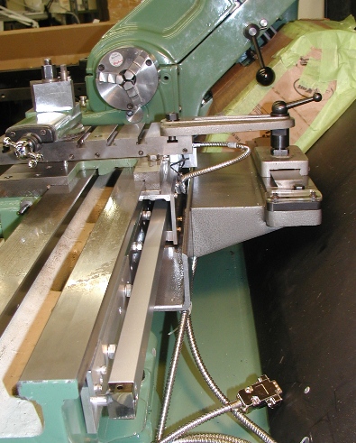
![TW-1.jpg]()
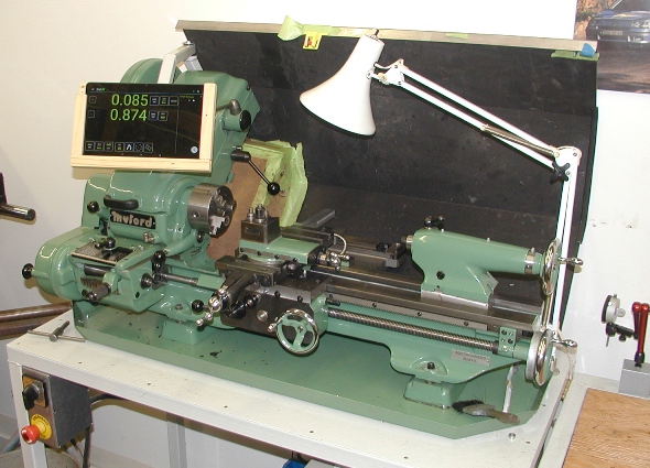
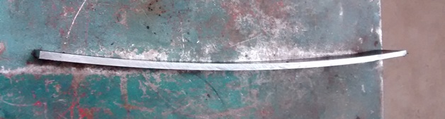
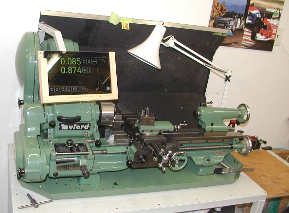
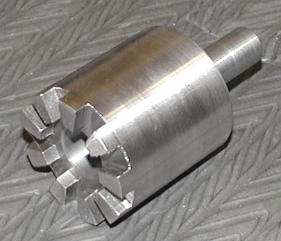
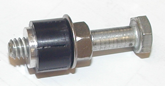
The crank is a simple affair with a set of complementary, tapered pieces which wedge into the (tiny) spindle bore on the Myford. It gets tightened with a threaded rod up the center of the shaft and driven by the big chrome knob. For trivia, the crank “hand hold” knob is a ball bearing idler roller from a VW 1.8T timing belt system left over from a routine belt change. I can’t seem to throw things like that out because they can come in handy LOL! The sleeve was a (successful") ) test piece.
) test piece.
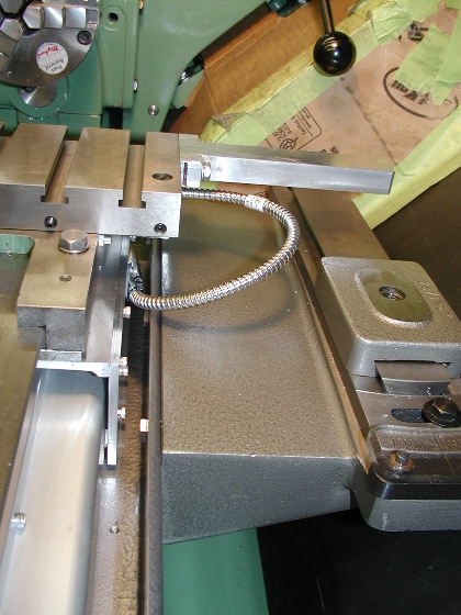
![TW-2.jpg]()
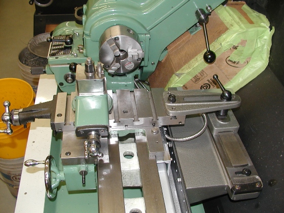
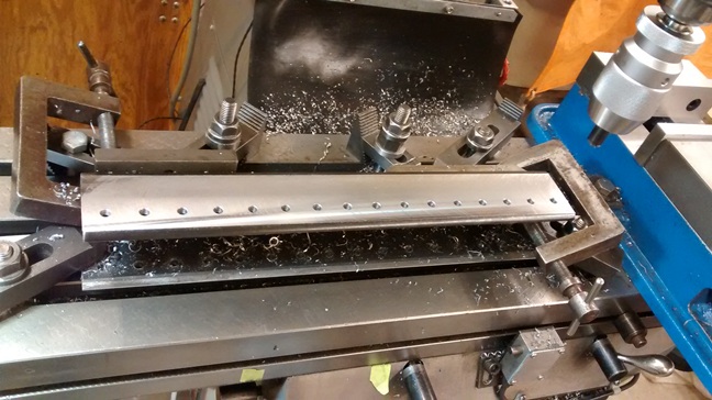
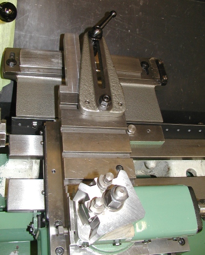
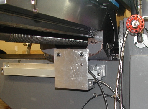
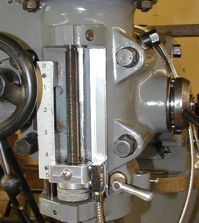
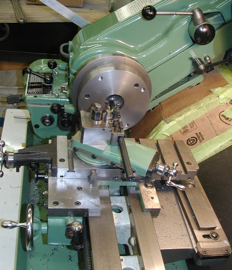
In this case the threading tool is a boring bar carrying a shop ground HSS tool and I used a 29.5 degree setup. Note the taper turning attachment at the back of the lathe bed, it’ll come up at a later date.
![TW-3.jpg]()
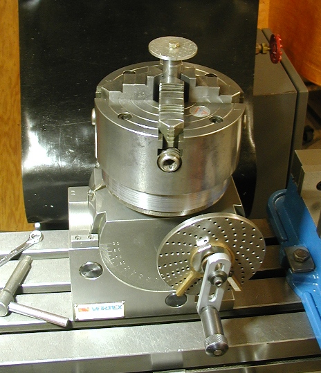
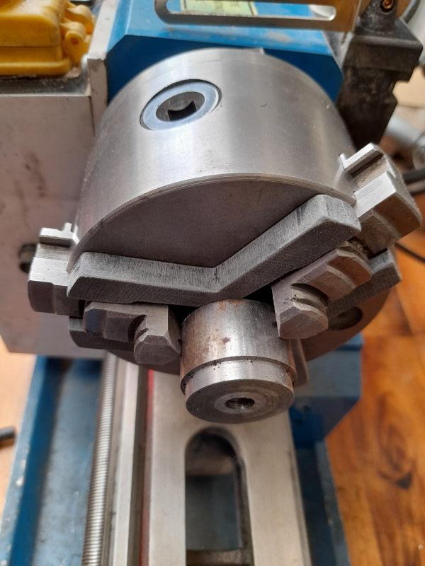
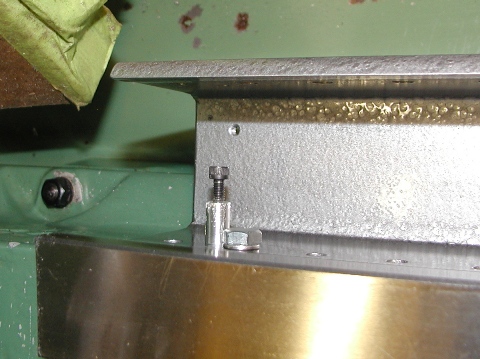
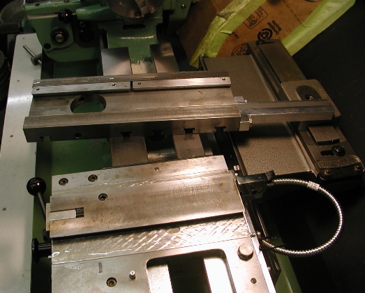
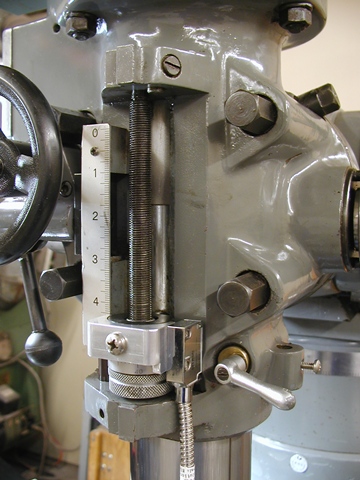
Final product: the 6” Burnerd on the Vertex DH, making a doodad for another project.
![TW-4.jpg]()
Starting point:
I received a nice Vertex BS-01 dividing head and an equally nice 6” Burnerd 4 jaw chuck with my First mill. I also received a grotty looking 3 jaw mystery chuck with replaceable jaw inserts but it’s going to sit on a shelf for a while longer, this posting is about a backing plate to join the Vertex & Burnerd but it will also accommodate the mystery chuck.
The big undiscovered country in this for me was cutting the 1-1/8 – 12 internal thread that would be needed to fit the Vertex. I got some good advice from members a while back and I was left with a suggestion, show how I did it because there was a little twist that’s apparently unusual for threading.
I prepped the rough HRS round stock on the mill and laid out the critical hole positions before digging into the internal threads. I was very conservative about the threading operation and I chose to use a hand crank to do the turning. This is one of the tricks the UK Myford users use to carefully cut threads in tight places.
Basically the operation is leave the half nuts engaged and wind the tool in and out of the bore by hand (backing off for clearance between cuts) until the thread is the desired size. Makes for very good control up to a face etc. as well. I’ve also used it for that. You can of course disengage the half nuts etc. but it's simpler to leave it engaged.
Unplug your machine if you try this.
The crank is a simple affair with a set of complementary, tapered pieces which wedge into the (tiny) spindle bore on the Myford. It gets tightened with a threaded rod up the center of the shaft and driven by the big chrome knob. For trivia, the crank “hand hold” knob is a ball bearing idler roller from a VW 1.8T timing belt system left over from a routine belt change. I can’t seem to throw things like that out because they can come in handy LOL! The sleeve was a (successful
) test piece.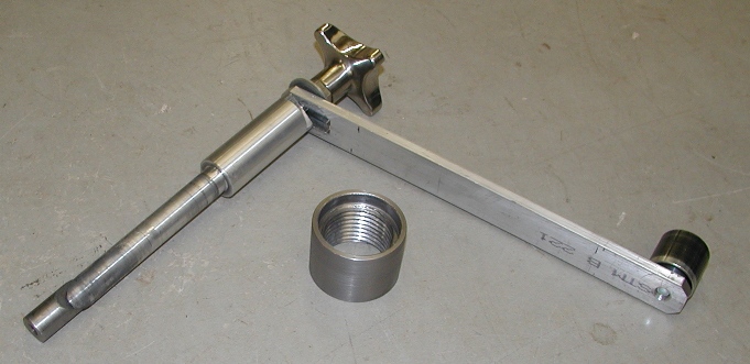
Final product: the 6” Burnerd on the Vertex DH, making a doodad for another project.