Tailstock alignment questions

Susquatch

Ultra Member
Administrator
Moderator
Premium Member
Yes, I agree, so I would think that you would do the test according to what your final operation will be. If you will be finish turning, rough turning, grinding, test under the same circumstances.

Ideally yes, but...... Ain't gunna happen in my shop. I only want to check and especially adjust the alignment once in a blue moon. Most of my work has very little stickout and is done up close and personal at the chuck where this isn't a big deal unless it's way off.

So ya, I will probably do the testing when I have the time because I am curious about it but for the most part I'll prolly be happy with a low load zero alignment. Lol!
 

Susquatch

Ultra Member
Administrator
Moderator
Premium Member
8" of stick out unsupported?

Yes. It has to be done that way. You need at least 8" and it MUST be unsupported. More improves accuracy. Keep in mind that you don't take big cuts and never go fast enough to create any significant centrifugal force.
 

Dabbler

ersatz engineer
With respect to @RobinHood and all the other comments:

My headstock test is on an unsupported centreless ground bar 1 1/2" in diameter and not turned, but measured at the chuck and at 12" from the chuck. If that is good, then I measure the tailstock using a tenths indicator, then perform a 2 collar test at 24". If they are all within reason I'm done.

Grinding can have forces equal to turning if the grinding cut is heavy and the turning is light. Also, I prefer to do the 2 collar test in aluminum, which is harder to grind.
 
I'm going to stir the pot, level is a mis-used term.

The biggest issue with any lathe is twist, with it alignment becomes near impossible to any form of accuracy.

As long as you don't have twist you don't have any issues, level just makes things easy to check and remove twist (along with work set up later), but as a reminder the lathe can have the twist removed and align perfectly without having to be level.

I worry less about the lathe being level in its length but am fanatically obsessed with it being level front to back (this is twist free).

Hopefully this gives a better understanding on what alignment and leveling is.
 
Last edited:

Susquatch

Ultra Member
Administrator
Moderator
Premium Member
I'm going to stir the pot, level is a mis-used term.

The biggest issue with any lathe is twist, with it alignment becomes near impossible to any form of accuracy.

As long as you don't have twist you don't have any issues, level just makes things easy to check and remove twist (along with work set up later), but as a reminder the lathe can have the twist removed and align perfectly without having to be level.

I worry less about the lathe being level in its length but am fanatically obsessed with it being level front to back (this is twist free).

Hopefully this gives a better understanding on what alignment and leveling is.

I think it's a waste of time to try and change the world. The vast majority call it levelling. We purists can call it whatever we want so I have decided to just use my own words and clarify what I mean by that and let everyone else freak out however they want. The bottom line is that in my head the bed (both sets of ways) need to be parallel to the spindle axis. Everyone else can call it whatever they want.

What I find more amazing is that the majority of people seem to confuse tailstock alignment (taper) with headstock alignment.

Even worse, is that other experienced machinists will invariably insist on giving everyone else a lecture on the differences. And don't try to argue. Just hold still and listen cuz you are gunna get the lecture whether or not you already know. LOL!

I should add here that it's all well intended. Experienced members forget who has experience and who doesn't. And they don't have any idea what a new member knows. So they just do what they feel they should do and instinctively give the lecture. And don't bother trying to stop it cuz everything you say will use different words that have different meaning to everyone else. Prolly best to just attend the lecture. ;)
 
Last edited:

PeterT

Ultra Member
Premium Member
The biggest issue with any lathe is twist, with it alignment becomes near impossible to any form of accuracy.
As long as you don't have twist you don't have any issues, level just makes things easy to check and remove twist (along with work set up later), but as a reminder the lathe can have the twist removed and align perfectly without having to be level.

Because of your particular choice of words & absence of pre-qualifiers, I am going to respectfully disagree. This has been discussed elsewhere on our forum, but the bottom line is you cannot lump all lathes into one bucket & make a sweeping generalization like that. The resultant conjecture is simply not true. Just so happens this came up on another forum recently & also referenced the same Blondihack video. Maybe this is the appropriate time to make a separate (maybe sticky) post on this subject because it doesn't pertain to TS alignment which can only come later in lathe setup process after HS is aligned.
I feel like we arrive at some collective level of understanding of HS alignment through discussion & pictures (a lot of work), then the subject pops up & we start all over again. So, because I'm lazy, I'll copy paste (my own verbiage snips) & see where it goes. If we go off tangent or too deep into a repetitive rabbit hole, then maybe time for a new post.


Most well meaning folks will tell you to start jacking the lathe feet in order to alter the lathe bed twist in order to correct taper cutting. This is often called 'lathe levelling' which is also a potentially confusing choice of words. If by levelling we are talking about using a precision level incrementally down the length of the bed in order to get a sense of current twist or bend condition, that's fine. But the lathe does not have to be level left to right.

I suspect the reason people recommend to bed alteration right away is out of tradition, because older vintage lathes had their headstock integrally cast with the lathe bed. There was nothing to adjust, the spindle axis was a function of the HS line bore & bearings. However, what many seem to miss (maybe including Blondihacks on her own lathe) is that most Asian lathes are constructed differently & have their headstock bolted to the ways as my manual shows. I have heard that some manufacturers 'key' the HS & bed together but I don't know to what extent or class of machine that may pertain to. Anyways, for Asian lathes including my 14x40, which is actually quite ordinary, it has micro-adjusting set screws to tweak the HS rotation viewed from the top. This is done at factory. But if the HS has become misaligned relative to the ways, then this effect will also cut a taper even if the bed twist is 100% perfect.

The best way to test for this is with a cylindrical test bar which has MT taper on one end to match your HS spindle socket. I bought a 24" made in India off Ebay for very reasonable cost. I was apprehensive but it is good value. They say cylindrically ground within 0.0001". I have no good means to validate that other than mic-ing down the length, but seems plenty accurate for hobby class machine HS & TS alignment work. Now with test bar inserted & cantilevered from the spindle, you can traverse an indicator down the length & this will tell you what's going on with regards to HS alignment - yawing in/out and/or pointing up/down. I have to caution you though, that breathing on the set screws can have a dramatic effect so proceed very carefully & only if you have a repeatable test bar. Maybe the factory omits mention of these adjustment screws so people don't start messing around, but that's pure speculation. With the spindle aligned to bed, then proceed to lathe twist (not the other way around).

I've read all the articles about cutting test bars & such. Nothing wrong with that & it has its place near the end of the procedure. Its just another means of verifying taper. You can save a lot of material & false readings by doing your best to initially validate geometry with test bar & indicator.


What I'm trying to convey is really quite simple. Upper sketch shows aligned lathe viewed from top. Zero bed twist. Lower picture shows the type of lathe where HS is mounted to bed & has the ability to be misaligned. It shows exaggerated HS angled toward rear of lathe, again zero bed twist. Would you concur the lower sketch would cut a tapered coupon?

This entire post is actually quite typical of many similar 'lathe levelling' posts one encounters on hobbyist forums. Its a familiar script. Someone notices they have taper cutting issue & the immediate solution offered is to jack the feet & twist the bed. The lathe type often does not even come up in in discussion as a qualifier. Or if it does, few people recognize that the HS is bolted to the ways & any misalignment there may well be the dominant if not entire source of taper cutting discrepancy. Then there is mysterious absence of the operator/parts manual even mentioning adjustment screws being there. If one has a larger lathe, say in 14" range, pulling the HS off & shimming is not exactly a trivial job although I recognize hobbyist skill sets vary. I'd certainly want to be sure before embarking down that path. Which is is exactly why a MT test bar is a valuable asset.

Just a guess on my part but maybe 20-30 years ago the chance of a hobbyist lathe being of the 'integrated' type (where no spindle alignment correction is possible) was certainly much higher than today. And yes, in that case you are stuck with what you have. Lathe twist is the only option & this presumes other factors like wear are good or minimal. But I would venture to guess a much higher percentage of hobby lathes in shops today are of the bolt-on style. Here is a popular vendor, quite typical of others including say Grizzly or other Asian importers. I count a dozen lathes from the smallest up to and including 14" swing which are bolt-on HS. Now if the factory did their job 100% and/or we have verified ourselves that HS is perfectly aligned in both vertical & horizontal plane, then we have arrived at the equivalent point of an 'integrated' lathe and hopefully relatively minor bed twist alteration may remedy remaining slight taper cutting. But if you have HS alignment problem & ignore it, and proceed to lathe twist, you are possibly attempting to fix the wrong problem or overcompensating which isn't the best solution. Of course this is a hobby so everyone is welcome to proceed as they see best. I'm just offering another perspective to the discussion.


Have a look at the picture I included in post#4 & the related description of how a test bar can be used. I attached picture of mine. Depending on your lathe you can use an MT sleeve adapter or just just buy the appropriate MT taper ended test bar. My spindle is MT5 so I use the MT3/MT5 adapter which I have confirmed is accurate. This allows me to use the MT3 test bar for subsequent tail stock work.

Pre-qualifiers: this relates to lathes of the type with removable HS where HS deviation is possible. This also assumes a newish machine with straight ways. The beds have not eroded away a hollow close to chuck. If that's the case, all bets are off, setup can only be a tradeoff compromise relative to chuck distance. Its an additional problem. And this discussion has zero to do with tailstock alignment. The TS must not be integrated into this initial test.

Personally, I think its best to get the bed as reasonably close to begin with even if it means somewhat undoing a prior setup. Why? because this is the very same datum surface that our DTI will ride along via the carriage when measuring the test bar pointing out into space completely independent of the ways. So as best you can, confirm the bed is not bending upward or downward relative to HS when viewed from side. And also is not twisting CW or CCW relative to HS when viewed from end. Unfortunately ($) to do this right is best accomplished with a precision level.

The test bar locates snugly into the HS MT socket and the extended portion exaggerates the HS axis relative to the 'mean' initial bed axis. Traverse an indicator down the length of the bar, both along the horizontal plane & vertical plane. We are attempting to discern if HS spindle axis is pointing inward/outward viewed from top and/or upward/downward viewed from the side relative to ways. If significant axis deviation is noted and dominated by the HS being mechanically out of alignment, that issue needs to be resolved first. If its a small deviation where we are satisfied HS alignment is as close as we will ever get, then we have arrived at the point of what I'll call the where classic methods like RDM come into play. The remainder of work is addressing lathe bed twist and ideally concluding with real cutting conditions. BTW if you doubt the significance of HS deviation as a source contribution, do the simple trig calculation for yourself. Consider a measly 0.001" over the length of HS block & extrapolate to the end of test bar. It translates into a significant amount of taper that actually represents a lot of equivalent lathe bed twist to accomplish. And something as measly as 0.001" HS rotation is nothing on a set screw, mere degrees of screw rotation depending on the thread pitch.

Here is my own summary. Others may have a different perspective. Taper cutting is a function of 2 somewhat independent sources. It could be 100% HS related, or it could be 100% lathe bed deviation related, or it could be some % blend of both. Unfortunately, the sources could serve to counter/mask one another or they also could cascade & exaggerate one another. Adjustment may well be an iterative thing, but hopefully by standardizing one deviation source (ideally the one with lesser +/- limits) in order to conform the more dominant or significant source, we can proceed logically & efficiently & not chase our tails too much.
 

Attachments

  • SNAG-2022-04-23 12.03.02 AM.jpg
    SNAG-2022-04-23 12.03.02 AM.jpg
    29.5 KB · Views: 2
  • SNAG-2022-04-23 12.03.11 AM.jpg
    SNAG-2022-04-23 12.03.11 AM.jpg
    18.1 KB · Views: 2
  • SNAG-2022-04-21 9.53.52 PM.jpg
    SNAG-2022-04-21 9.53.52 PM.jpg
    98.6 KB · Views: 2
  • IMG_5727_edited-1.jpg
    IMG_5727_edited-1.jpg
    38.7 KB · Views: 2
  • IMG_5728_edited-1.jpg
    IMG_5728_edited-1.jpg
    44 KB · Views: 2
  • IMG_5729_edited-1.jpg
    IMG_5729_edited-1.jpg
    28.4 KB · Views: 2
Last edited:
Because of your particular choice of words & absence of pre-qualifiers, I am going to respectfully disagree. This has been discussed elsewhere on our forum, but the bottom line is you cannot lump all lathes into one bucket & make a sweeping generalization like that. The resultant conjecture is simply not true. Just so happens this came up on another forum recently & also referenced the same Blondihack video. Maybe this is the appropriate time to make a separate (maybe sticky) post on this subject because it doesn't pertain to TS alignment which can only come later in lathe setup process after HS is aligned.
I feel like we arrive at some collective level of understanding of HS alignment through discussion & pictures (a lot of work), then the subject pops up & we start all over again. So, because I'm lazy, I'll copy paste (my own verbiage snips) & see where it goes. If we go off tangent or too deep into a repetitive rabbit hole, then maybe time for a new post.


Chunk 1
Most well meaning folks will tell you to start jacking the lathe feet in order to alter the lathe bed twist in order to correct taper cutting. This is often called 'lathe levelling' which is also a potentially confusing choice of words. If by levelling we are talking about using a precision level incrementally down the length of the bed in order to get a sense of current twist or bend condition, that's fine. But the lathe does not have to be level left to right.

I suspect the reason people recommend to bed alteration right away is out of tradition, because older vintage lathes had their headstock integrally cast with the lathe bed. There was nothing to adjust, the spindle axis was a function of the HS line bore & bearings. However, what many seem to miss (maybe including Blondihacks on her own lathe) is that most Asian lathes are constructed differently & have their headstock bolted to the ways as my manual shows. I have heard that some manufacturers 'key' the HS & bed together but I don't know to what extent or class of machine that may pertain to. Anyways, for Asian lathes including my 14x40, which is actually quite ordinary, it has micro-adjusting set screws to tweak the HS rotation viewed from the top. This is done at factory. But if the HS has become misaligned relative to the ways, then this effect will also cut a taper even if the bed twist is 100% perfect.

The best way to test for this is with a cylindrical test bar which has MT taper on one end to match your HS spindle socket. I bought a 24" made in India off Ebay for very reasonable cost. I was apprehensive but it is good value. They say cylindrically ground within 0.0001". I have no good means to validate that other than mic-ing down the length, but seems plenty accurate for hobby class machine HS & TS alignment work. Now with test bar inserted & cantilevered from the spindle, you can traverse an indicator down the length & this will tell you what's going on with regards to HS alignment - yawing in/out and/or pointing up/down. I have to caution you though, that breathing on the set screws can have a dramatic effect so proceed very carefully & only if you have a repeatable test bar. Maybe the factory omits mention of these adjustment screws so people don't start messing around, but that's pure speculation. With the spindle aligned to bed, then proceed to lathe twist (not the other way around).

I've read all the articles about cutting test bars & such. Nothing wrong with that & it has its place near the end of the procedure. Its just another means of verifying taper. You can save a lot of material & false readings by doing your best to initially validate geometry with test bar & indicator.


Chunk 2
What I'm trying to convey is really quite simple. Upper sketch shows aligned lathe viewed from top. Zero bed twist. Lower picture shows the type of lathe where HS is mounted to bed & has the ability to be misaligned. It shows exaggerated HS angled toward rear of lathe, again zero bed twist. Would you concur the lower sketch would cut a tapered coupon?

This entire post is actually quite typical of many similar 'lathe levelling' posts one encounters on hobbyist forums. Its a familiar script. Someone notices they have taper cutting issue & the immediate solution offered is to jack the feet & twist the bed. The lathe type often does not even come up in in discussion as a qualifier. Or if it does, few people recognize that the HS is bolted to the ways & any misalignment there may well be the dominant if not entire source of taper cutting discrepancy. Then there is mysterious absence of the operator/parts manual even mentioning adjustment screws being there. If one has a larger lathe, say in 14" range, pulling the HS off & shimming is not exactly a trivial job although I recognize hobbyist skill sets vary. I'd certainly want to be sure before embarking down that path. Which is is exactly why a MT test bar is a valuable asset.

Just a guess on my part but maybe 20-30 years ago the chance of a hobbyist lathe being of the 'integrated' type (where no spindle alignment correction is possible) was certainly much higher than today. And yes, in that case you are stuck with what you have. Lathe twist is the only option & this presumes other factors like wear are good or minimal. But I would venture to guess a much higher percentage of hobby lathes in shops today are of the bolt-on style. Here is a popular vendor, quite typical of others including say Grizzly or other Asian importers. I count a dozen lathes from the smallest up to and including 14" swing which are bolt-on HS. Now if the factory did their job 100% and/or we have verified ourselves that HS is perfectly aligned in both vertical & horizontal plane, then we have arrived at the equivalent point of an 'integrated' lathe and hopefully relatively minor bed twist alteration may remedy remaining slight taper cutting. But if you have HS alignment problem & ignore it, and proceed to lathe twist, you are possibly attempting to fix the wrong problem or overcompensating which isn't the best solution. Of course this is a hobby so everyone is welcome to proceed as they see best. I'm just offering another perspective to the discussion.


Chunk-3
Have a look at the picture I included in post#4 & the related description of how a test bar can be used. I attached picture of mine. Depending on your lathe you can use an MT sleeve adapter or just just buy the appropriate MT taper ended test bar. My spindle is MT5 so I use the MT3/MT5 adapter which I have confirmed is accurate. This allows me to use the MT3 test bar for subsequent tail stock work.

Pre-qualifiers: this relates to lathes of the type with removable HS where HS deviation is possible. This also assumes a newish machine with straight ways. The beds have not eroded away a hollow close to chuck. If that's the case, all bets are off, setup can only be a tradeoff compromise relative to chuck distance. Its an additional problem. And this discussion has zero to do with tailstock alignment. The TS must not be integrated into this initial test.

Personally, I think its best to get the bed as reasonably close to begin with even if it means somewhat undoing a prior setup. Why? because this is the very same datum surface that our DTI will ride along via the carriage when measuring the test bar pointing out into space completely independent of the ways. So as best you can, confirm the bed is not bending upward or downward relative to HS when viewed from side. And also is not twisting CW or CCW relative to HS when viewed from end. Unfortunately ($) to do this right is best accomplished with a precision level.

The test bar locates snugly into the HS MT socket and the extended portion exaggerates the HS axis relative to the 'mean' initial bed axis. Traverse an indicator down the length of the bar, both along the horizontal plane & vertical plane. We are attempting to discern if HS spindle axis is pointing inward/outward viewed from top and/or upward/downward viewed from the side relative to ways. If significant axis deviation is noted and dominated by the HS being mechanically out of alignment, that issue needs to be resolved first. If its a small deviation where we are satisfied HS alignment is as close as we will ever get, then we have arrived at the point of what I'll call the where classic methods like RDM come into play. The remainder of work is addressing lathe bed twist and ideally concluding with real cutting conditions. BTW if you doubt the significance of HS deviation as a source contribution, do the simple trig calculation for yourself. Consider a measly 0.001" over the length of HS block & extrapolate to the end of test bar. It translates into a significant amount of taper that actually represents a lot of equivalent lathe bed twist to accomplish. And something as measly as 0.001" HS rotation is nothing on a set screw, mere degrees of screw rotation depending on the thread pitch.

Here is my own summary. Others may have a different perspective. Taper cutting is a function of 2 somewhat independent sources. It could be 100% HS related, or it could be 100% lathe bed deviation related, or it could be some % blend of both. Unfortunately, the sources could serve to counter/mask one another or they also could cascade & exaggerate one another. Adjustment may well be an iterative thing, but hopefully by standardizing one deviation source (ideally the one with lesser +/- limits) in order to conform the more dominant or significant source, we can proceed logically & efficiently & not chase our tails too much.
Hate to say this you are chasing your tail.

Align bed on centers, no chucks to start. This ensures your slides do not cause taper as they travel. If you do not do this first, everything else you do is suspect. Start and worry about this first. If you still have issues proceed with the rest otherwise don't mess with it.

Align head stock afterward with a collet if you have it, if not use your chuck(s).

Tailstock need to be repositioned as required to match head stock.

Finally most chucks are aligned with grinding.
 

PeterT

Ultra Member
Premium Member
Hate to say this you are chasing your tail.

Align bed on centers, no chucks to start. This ensures your slides do not cause taper as they travel. If you do not do this first, everything else you do is suspect. Start and worry about this first. If you still have issues proceed with the rest otherwise don't mess with it.

Align head stock afterward with a collet if you have it, if not use your chuck(s).

Tailstock need to be repositioned as required to match head stock.

Finally most chucks are aligned with grinding.
Huh? Where in my description am I suggesting a chuck or collet being used in any aspect of alignment process? It is completely absent of a chuck or collet.
I am also saying TS alignment comes after HS/bed alignment.
What does chuck grinding have to do with HS/bed alignment?
 
Huh? Where in my description am I suggesting a chuck or collet being used in any aspect of alignment process? It is completely absent of a chuck or collet.
I am also saying TS alignment comes after HS/bed alignment.
What does chuck grinding have to do with HS/bed alignment?
Well....Chuck 1, Chuck 2 and Chuck 3.....

I am going to suggest the the MT test bar is good for the latter half of the set up, but again between centers is the correct way for the initial alignment, as you are potentionally adding errors with the MT test bar even if it is perfect.
 

PeterT

Ultra Member
Premium Member
It says Chunk, not Chuck. As in 'chunks' of text copy/pasted from my other post I referred to. Obviously very confusing, I will delete it.
1650848922772.png

In terms of the rest of your comment, I can see this is a losing battle & anymore input from me is not going to help matters. You obviously have a specific view of what's going on & that's cool. Good luck.
 

Dabbler

ersatz engineer
Boy, this topic keeps blowing up. On hobby machinist it blew up several times last year, too.

I wish the term would become 'lathe setup' or 'setting up your lathe to turn parallel and perpendicular' instead of 'leveling your lathe'...

One post recently here or on another forum suggested that lathes turn a face slightly convex - which I have *never* seen (!!) I have 3 lathes, and have used a dozen more, and it certainly has not been my experience. Your experience may vary.
 

Brent H

Ultra Member
For what it is worth my two lathes are set at an incline so that the tailstock self feeds - wicked awesome for drilling holes and soooooo much easier on the tailstock advance screw......

Just saying.................:D:eek::oops:o_O

sorry...just tied up after a great ride across the seas................
 

DPittman

Ultra Member
Premium Member
Boy, this topic keeps blowing up. On hobby machinist it blew up several times last year, too.

I wish the term would become 'lathe setup' or 'setting up your lathe to turn parallel and perpendicular' instead of 'leveling your lathe'...

One post recently here or on another forum suggested that lathes turn a face slightly convex - which I have *never* seen (!!) I have 3 lathes, and have used a dozen more, and it certainly has not been my experience. Your experience may vary.
I've read also somewhere that some lathes (especially small lathes) tend to face with a bit of a convex surface. I have thought I may have observed that in the past and chalked it up to the tool bit not cutting as efficiently as the sfm decreased with the smaller diameter as the tool bit traveled from the outside diameter to the center of the work piece?
 

Mcgyver

Ultra Member
One post recently here or on another forum suggested that lathes turn a face slightly convex - which I have *never* seen (!!) I have 3 lathes, and have used a dozen more, and it certainly has not been my experience. Your experience may vary.

Convex? The lathe is supposed to cut concave. Its how they (should!) come from the factory and you specifically put it there when reconditioning.

Why? There is no such thing as "dead on", everything is tolerances. If you tried to make it cut at exactly 90, some lathes would be 90.001 and others 89.999, i.e. some would cut convex and some concave. On those that cut convex, anything you faced wouldn't sit flat on the face but would rock. Not desirable.

Its a very small amount. Been awhile since I've done so I'd probably look it up before doing it again, but its 3-5 tenths over a foot. Here's me checking it on my DSG as I scrape in the cross slide. You sweep the pin in one location and move to another.

5f2uGWS.jpg
 
Last edited:

Susquatch

Ultra Member
Administrator
Moderator
Premium Member
I've read also somewhere that some lathes (especially small lathes) tend to face with a bit of a convex surface. I have thought I may have observed that in the past and chalked it up to the tool bit not cutting as efficiently as the sfm decreased with the smaller diameter as the tool bit traveled from the outside diameter to the center of the work piece?

One post recently here or on another forum suggested that lathes turn a face slightly convex - which I have *never* seen (!!) I have 3 lathes, and have used a dozen more, and it certainly has not been my experience. Your experience may vary.

I have seen it on rare occasions. I don't believe the size of the lathe matters. In fact, I don't think the lathe matters. The lathe itself wants to cut a flat face. Personally, I THINK (very dangerous thing to do) that it is caused by a variety of factors. For me, it has only happened with high strength steel. I like to use old Bolts (huge, big, and small) as stock. Grade 8 Bolts sometimes do this, but only when I use inserts not when I use HSS (another whole discussion we have beat to death before). I can always tell that it happened when the cutting bit only cuts the center portion as its drawn out too. I do not consider this to be a big issue. It isn't any different than making a long cut on small diameter stock with stick out. Tool pressure, part resistance to that pressure, sharpness, speed, depth of cut, etc etc all matter.

At the risk of sounding like a bit of an idiot though..... Is it possible that some cross slides on some small lathes become weak and lose rigidity as they are moved away from the operator? If so, I would think tool stick out would also be a factor. Just speculating here.
 

Susquatch

Ultra Member
Administrator
Moderator
Premium Member
The lathe isn't supposed to cut convex, its supposed to cut concave. Its how they (should!) come from the factory and you specifically put it there when reconditioning.

Why? There is no such thing as "dead on", everything is tolerances. If you tried to make it cut at exactly 90, some lathes would be 90.001 and others 89.999, i.e. some would cut convex and some concave. On those that cut convex, anything you faced wouldn't sit flat on the face but would rock. Not desirable.

Its a very small amount. Been awhile since I've done so I'd probably look it up before doing it again, but its 3-5 tenths over a foot. Here's me checking it on my DSG as I scrape in the cross slide. You sweep the pin in one location and move to another.

5f2uGWS.jpg

I considered commenting on this too but figured someone like you would blow it all out of the water by adding a comment like: How would you set that up to compensate for various tool stick outs that ride a different part of the cross-slide wave? LOL!

Just pulling your chain. No need for any big convoluted explanation. Unless you can't help yourself...... ;)
 

Mcgyver

Ultra Member
Boy, this topic keeps blowing up. On hobby machinist it blew up several times last year, too.

Yes, one of the classic machining tinder boxes. There are literally a lot of moving parts and tons of variables.

When you make, or at least remake which is what reconditioning is, the geometry of a machine, you need to follow a process that is exacting. There is not much equipment required, but if you don't have the right equipment, you get it, e.g. a Starrett 199 master precision level. Its different if you are just trying to set up a lathe; it's not realistic to say you have to spend $400-500 (and that's used) for a 199.

Which leads to a problem. I don't think I've used or seen a lathe upclose where headstock isn't solidly registered. They have all had inverted V ways or are pinned. You can rely on it (or least you could in the past) coming from the factory correctly aligned. This eliminated HS alignment as an issue.

One thing I learned here is that is often no longer the case. After watching how SM did it over a few days, I can see why manufactures would see it as a huge cost savings not producing lathes in this manner, but imo its a real disservice. SM had three guys full time scraping HS, TS and carriages in to the ground bed. Its imo the right way, but it is expensive.

Nevertheless, if this is your the current reality, you can't solve this problem without having a way to detect twist separate from HS misalignment. I haven't read everything that is here, but this challenge is no different than that faced by the person reconditioning the machine. The correct procedure is to remove the bed twist via leveling before working on scraping the HS in (HS alignment) because if you don't, any reading (or tests cuts) you make with the carriage moving over the bed, will be erroneous if bed has twist. If you don't have a 199, use the best you've got.

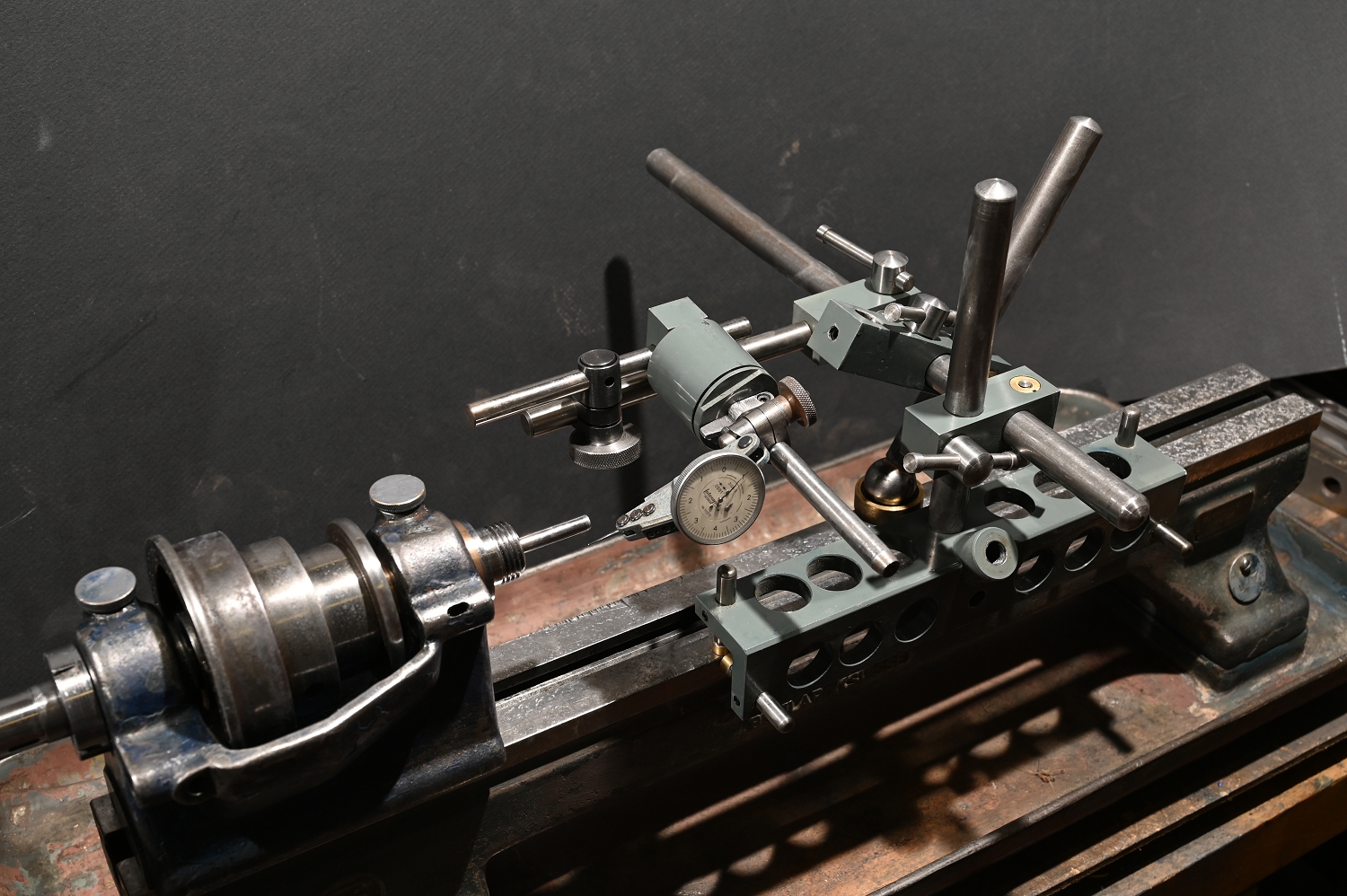
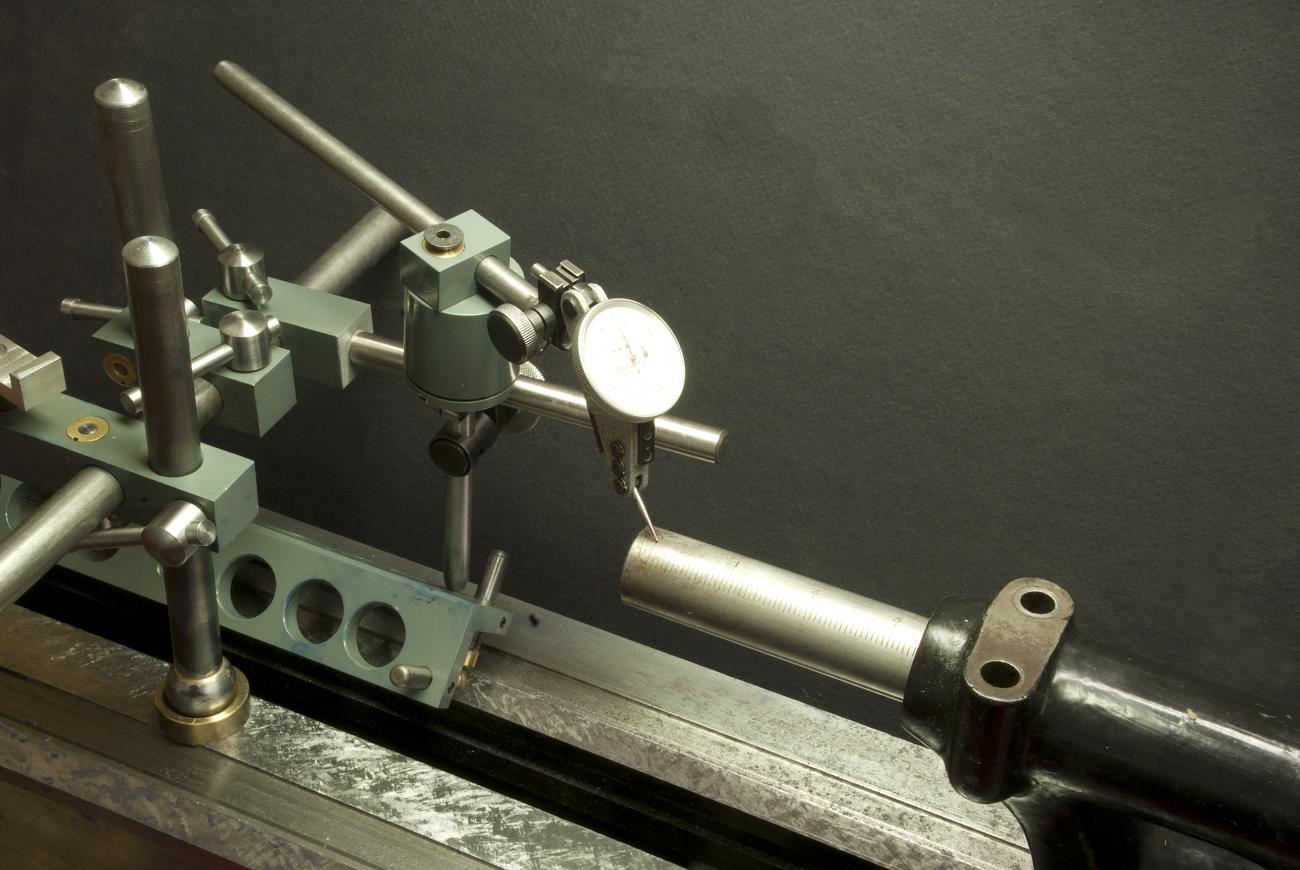
You do have an additional problem: wear. Wear can mean even with zero twist in the bed, relying on the carriage travel for detecting things relative to the headstock introduces error. There is little you can do about this, but one technique is to use a Kingway (or my version of it shown below which I think has several improvements) to slide along unworn surfaces. This is better than nothing and good for surveying as well, as advocated by scraper Richard King. (Having seen lathes been made, I do disagree with him as to how perfectly reliable these surfaces are or how exact their vectors matches those of the original ground surface as, at least at SM, they were done on different machines and setups than the way grinding).

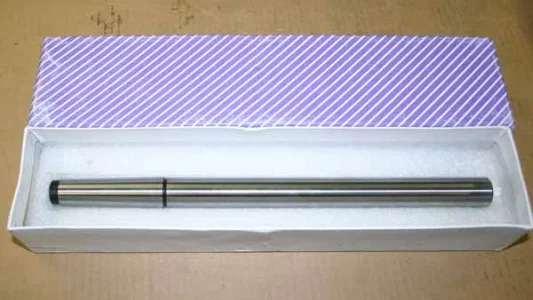
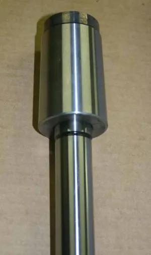
A couple of other ideas. The best way to align the headstock, with the bed first leveled and a reliable surface to move along, is to mount a precisely ground cylinder, like a cylindrical square in the lathe. I say best because the error introduced with workholding doesn't matter. Weight reduced (holes) and a few inches in diameter is ideal. Just put it in the three jaw, alignment does not matter.

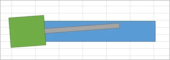
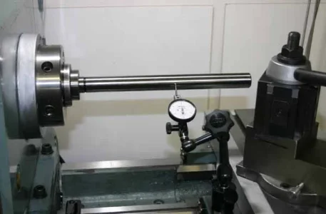
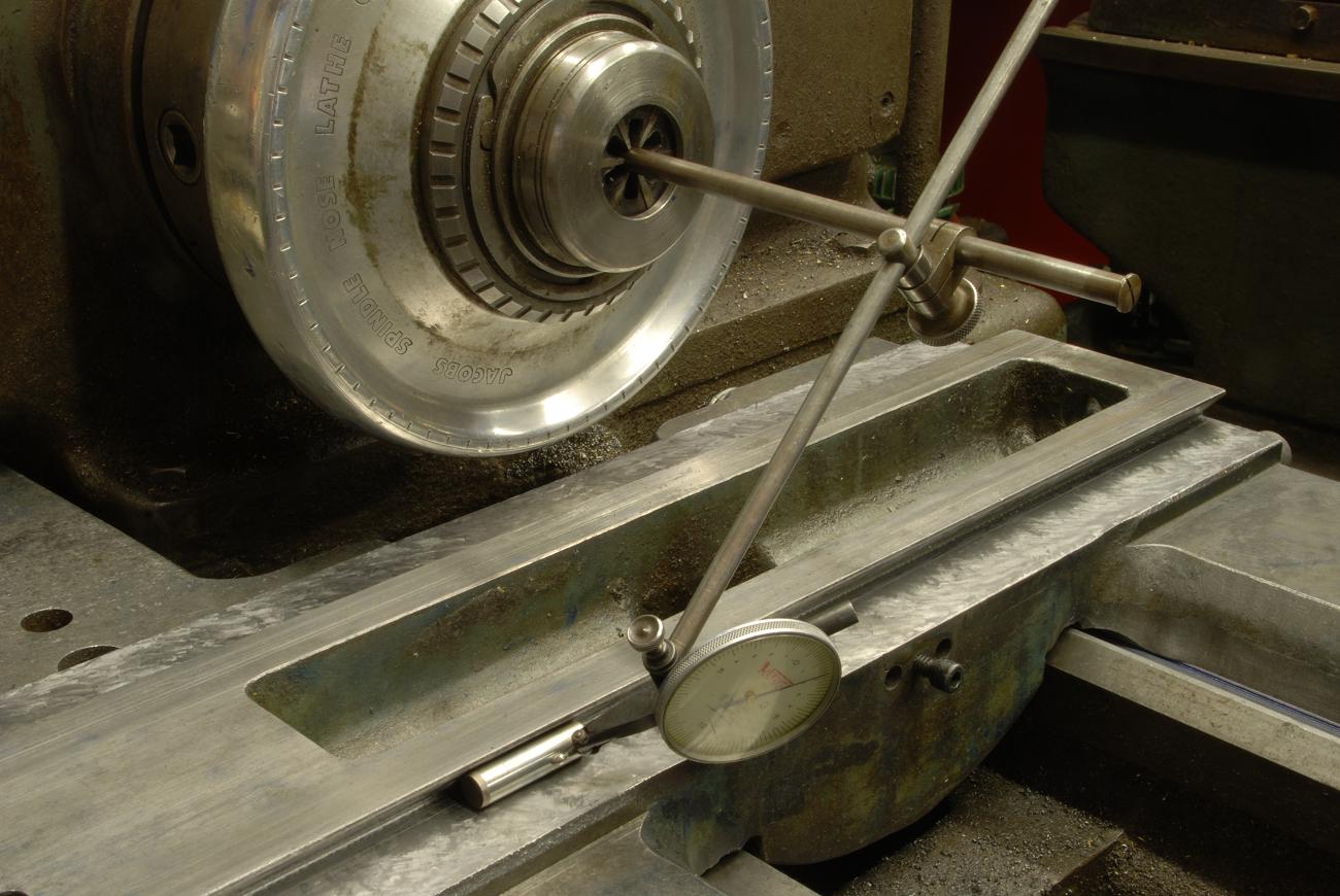
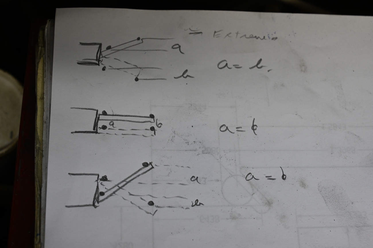
You take a reading at the chuck, then at the end - two planes. Then you rotate it 180 degrees and do so again. Looking at the differences between them tells the story. In my diagram, if A=B, its aligned. When scraping of course you have to do this in two planes, ZX and ZY but for checking alignment only ZY is looked at. Using the A=B difference method eliminates the need for test bars and eliminates any source of error in mounting - even the taper spindle mount introduces some error. You also want to sweep the indicator, not drag it along the work which can introduce error as the work may be going up or down hill in the other direction - see photo of sweep tool.

Despite all this, turning a long cylinder parallel to few tenths remains a BIG challenge. The only time I might take a test cut for alignment is with this type of job....wear, tailstock quill clearance and concrete slabs moving making things somewhat "dynamic". This is where figuring out what mounting bolt to tweak a few degrees turn pays off :)


Rx4mTqc.jpg


RuxwWpf.jpg


ClYGGr0.png


tk1OdHe.jpg
 
Last edited:

Mcgyver

Ultra Member
I considered commenting on this too but figured someone like you would blow it all out of the water by adding a comment like: How would you set that up to compensate for various tool stick outs that ride a different part of the cross-slide wave? LOL!

Just pulling your chain. No need for any big convoluted explanation. Unless you can't help yourself...... ;)

You lost me on that one. I was describing how a lathe should be set up, has nothing to do with tool overhang afaik
 
Last edited:
Top