Tachometers

Rauce

Ultra Member
@Rauce I just received a reply from Trexon:


Hi, David:-

Tachulator is 115.00 + 10.00 shipping + 5% GST (BC) = 131.25 CAD
including sensor.

Payment can be by Paypal or Interac to this e-mail.

It would take a couple days to finish off your unit. Please let
me know if you would like to go ahead.

Best regards,
--sp

I might go for this option...
As did I! I probably will order one as well.
 

whydontu

I Tried, It Broke
Premium Member
I wish I had researched the Tachulator before I built my Arduino version. The Tachulator does similar functions to mine, maybe not as convenient but looks more robust than an Arduino. At $132 including shipping and tax is looks like a great option. I’ve probably got 20 hours into building and coding mine.
 

DavidR8

Scrap maker
Administrator
Moderator
Premium Member
I wish I had researched the Tachulator before I built my Arduino version. The Tachulator does similar functions to mine, maybe not as convenient but looks more robust than an Arduino. At $132 including shipping and tax is looks like a great option. I’ve probably got 20 hours into building and coding mine.
I only just learned about the Tachulator on March 27 from a post on Hobby Machinist.
 

YYCHM

(Craig)
Premium Member
I wish I had researched the Tachulator before I built my Arduino version. The Tachulator does similar functions to mine, maybe not as convenient but looks more robust than an Arduino. At $132 including shipping and tax is looks like a great option. I’ve probably got 20 hours into building and coding mine.

Ya, but look at how much fun you had figuring it out. The learning experience is priceless.
 

Susquatch

Ultra Member
Administrator
Moderator
Premium Member
Not that this is what you're looking for, but as a cheap "check the RPM" thing...these do work:
Worth grabbing if this isn't something you're too worried about all the time (like if a few key marks on your speed dial would get you close enough).

@Rauce, @SomeGuy, & @David_R8 .

I actually like the optical tach. As a cheap check the tach device, they work. I have an old mechanical one that counts revolutions and you use with a stop watch. It is dynamite, but one of my boys borrowed it to check his marine engine and it never came home.

If you are having trouble with the optical tach, try using it at about 12 inches from the reflective tape, and use black electrical tape to mask off all the way around the shaft but where you have the reflective tape. That dramatically improves contrast and steadies up the reading.

You guys might like that gizmo from Trexon, but keep in mind that using the Arduino ala @whydontu, is MUCH more flexible and adaptable. Plus you can always add features. You cannot do that with the Trexon which is strictly "what you see is what you get".
 

DavidR8

Scrap maker
Administrator
Moderator
Premium Member
So a bunch of surfing last night and for about $20 I can build an Arduino based tachometer that uses infrared light as the trigger.
So I added some electronic components into my shopping cart:

I already have an Arduino so there's that :)
 

whydontu

I Tried, It Broke
Premium Member
So a bunch of surfing last night and for about $20 I can build an Arduino based tachometer that uses infrared light as the trigger.
So I added some electronic components into my shopping cart:

I already have an Arduino so there's that :)
I’ve probably tried a dozen different boxes of Arduino tachometer codes. This one is the best, except because it uses interrupts to measure time between pulses it can’t be used for any other functions.On the other hand, it’s very stable and very accurate.


DavidR8

Scrap maker
Administrator
Moderator
Premium Member

Susquatch

Ultra Member
Administrator
Moderator
Premium Member
I’ve probably tried a dozen different boxes of Arduino tachometer codes. This one is the best, except because it uses interrupts to measure time between pulses it can’t be used for any other functions.On the other hand, it’s very stable and very accurate.


I don't understand this @whydontu. I must be missing something. I would have thought the exact opposite.

The whole purpose of the processor interrupt system is to allow the processor to do other things when it isn't busy with a priority task.

In a tach, the processor would be busy calculating sfm or stress or or or until it gets an interrupt to get an rpm count, reset the counters, and update the display. Then it would exit the tach interrupt routine and pick up where it left off on the other lower priority task.

What am I missing?
 

whydontu

I Tried, It Broke
Premium Member
I don't understand this @whydontu. I must be missing something. I would have thought the exact opposite.

The whole purpose of the processor interrupt system is to allow the processor to do other things when it isn't busy with a priority task.

In a tach, the processor would be busy calculating sfm or stress or or or until it gets an interrupt to get an rpm count, reset the counters, and update the display. Then it would exit the tach interrupt routine and pick up where it left off on the other lower priority task.

What am I missing?
major snag with this one - rising edge of pulse kicks the interrupt, times until next rising edge, and calculates t2-t1. If the quill stops turning, it hangs until the next rising edge to reset the timer. Tach is now stuck.

My programming skills arent good enough to interpose an If statement to detect when the quill is stopped. I tried multiple ways to stick my subroutines in the timing gap to read the material and cutter values to calculate SFM, but never got it to work.

I have code that works in real time, but I’m only going to send it out to the world if no one laughs at my code…
 

SomeGuy

Hobbyist
major snag with this one - rising edge of pulse kicks the interrupt, times until next rising edge, and calculates t2-t1. If the quill stops turning, it hangs until the next rising edge to reset the timer. Tach is now stuck.

My programming skills arent good enough to interpose an If statement to detect when the quill is stopped. I tried multiple ways to stick my subroutines in the timing gap to read the material and cutter values to calculate SFM, but never got it to work.

I have code that works in real time, but I’m only going to send it out to the world if no one laughs at my code…

I'm a software dev (well, architect now) by day...can I take a look and maybe I can make a few suggestions?
 

DavidR8

Scrap maker
Administrator
Moderator
Premium Member
major snag with this one - rising edge of pulse kicks the interrupt, times until next rising edge, and calculates t2-t1. If the quill stops turning, it hangs until the next rising edge to reset the timer. Tach is now stuck.

My programming skills arent good enough to interpose an If statement to detect when the quill is stopped. I tried multiple ways to stick my subroutines in the timing gap to read the material and cutter values to calculate SFM, but never got it to work.

I have code that works in real time, but I’m only going to send it out to the world if no one laughs at my code…
No laughing on my part!
 

Susquatch

Ultra Member
Administrator
Moderator
Premium Member
major snag with this one - rising edge of pulse kicks the interrupt, times until next rising edge, and calculates t2-t1. If the quill stops turning, it hangs until the next rising edge to reset the timer. Tach is now stuck.

My programming skills arent good enough to interpose an If statement to detect when the quill is stopped. I tried multiple ways to stick my subroutines in the timing gap to read the material and cutter values to calculate SFM, but never got it to work.

I have code that works in real time, but I’m only going to send it out to the world if no one laughs at my code…

I see. Well that's a different outcome than I expected!

How about making the software "assume" it stopped unless something tells it didn't. Sort of an A** backward approach?
 

whydontu

I Tried, It Broke
Premium Member
File is a plain txt file, I couldn't upload as an .ino file.

No snickering or snide comments about my coding is allowed, I'll start to cry. I'd be happy to have a better programmer clean up this code, hint hint...

And no whining about my using two pots to select cutter diameter and material, it's cheap, simple to code, and means each dial only has one function, a defining characteristic of good HMI design. I could have changed it to a rotary encoder, but Arduino nanos only have two interrupt pins, so it would need a menu system and multiple steps to select inputs, so why bother?

My mill has a 16-hole disc on the quill, just change the RPM Array formula to match the number of pulses available per revolution. And any IR sensor will work, I first set it up with a reflective sensor and a single chunk of white tape on the quill.

My mill tops out a 2000 RPM, so my <cal rpm> function displays ">2000" for any calculated rpm values above 2000, no point in displaying something my mill can't do. YMMV

There is no code restrictions on the actual tachometer display, I've successfully tested this at 5,000 RPM with good results.

/*
Modified from:

Author: Chris @ PyroElectro.com
Date: 8/26/2012
Description:
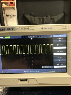
This project is meant to capture interrupt counts from an IR breakbeam circuit
and display them as an RPM number on a 16x2 LCD module.

Full Project Details:
http://www.pyroelectro.com/tutorials/tachometer_rpm_arduino/
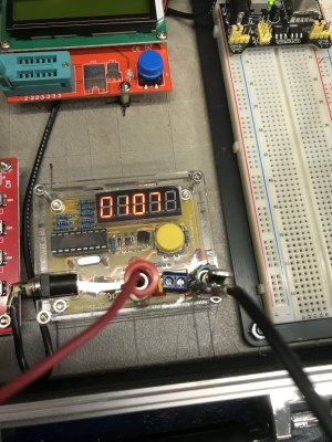
components

Arduino Nano
Nano screw terminal board
20x4 LCD with I2C interface
Two 10K pots
LM393 slot-type iR speed sensor module
USB power adapter
case, etc.
*/
#include <Wire.h>
#include <LiquidCrystal_I2C.h>

LiquidCrystal_I2C lcd(0x27, 20, 4);

// SDA pin A4
// SCL pin A5


volatile float time = 0;
volatile float time_last = 0;
volatile int rpm_array[7] = {0, 0, 0, 0, 0, 0, 0};

void setup()
{
//Digital Pin 2 Set As An Interrupt
attachInterrupt(0, fan_interrupt, FALLING);

// set up the LCD's number of columns and rows:
lcd.begin();
// Print the main header to the LCD.
lcd.setCursor(0, 0);
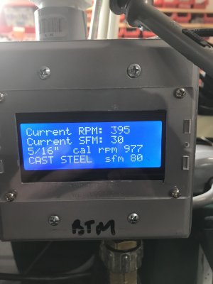
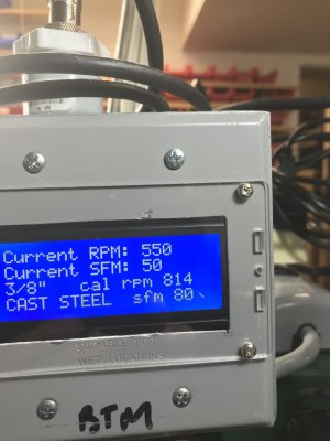
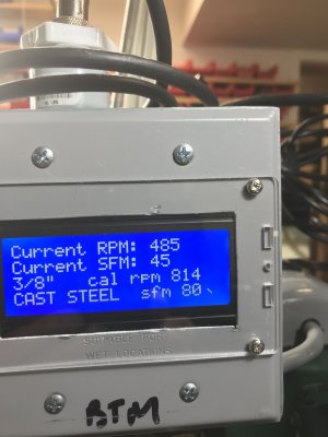
lcd.print("Current RPM: ");
}

void loop()
{
int rpm = 0;

while (1) {

//Slow Down The LCD Display Updates
delay(500);

// fill array of cutter diameters
float CutterSixteens[] = {1, 2, 3, 4, 5, 6, 7, 8, 9, 10, 11, 12, 13, 14, 15, 16, 20, 24, 32, 40, 48, 64}; // cutter diamters in sixteenths
char* CutterNames[] = {"1/16\" ", "1/8\" ", "3/16\" ", "1/4\" ", "5/16\" ", "3/8\" ", "7/16\" ", "1/2\" ", "9/16\" ", "5/8\" ", "11/16\"", "3/4\" ", "13/16\"", "7/8\" ", "15/16\"", "1\" ", "1-1/4\"", "1-1/2\"", "2\" ", "2-1/2\"", "3\" ", "4\" "}; // cutter descriptions in text
int HSSsfm[] = {300, 150, 100, 80, 50, 90, 80, 40, 50, 60, 40, 175, 500}; // book values for SFM for materials

// Set cutter diameter
int CutterDial = analogRead(A2); // 10K pot wiper to analog Pin 2
int Cutter = map(CutterDial, 0, 1023, 0, 21); // maps pot to 1 of 12 cutter diamters

char* MatNames[] = {"ALUMINUM ", "BRASS ", "COPPER ", "SOFT IRON ", "HARD IRON ", "MILD STEEL ", "CAST STEEL ", "ALLOY STEEL", "TOOL STEEL ", "S-STEEL 303", "S-STEEL 316", "PLASTICS ", "WOOD "};

// Set material
int MatList = analogRead(A1); // 10K pot wiper to analog Pin 1
int Material = map(MatList, 0, 1023, 0, 13); // maps pot to 1 of 14 material types

float SFM = (((CutterSixteens[Cutter] / 16) * rpm) / 3.82);
int smoothedSFM = SFM * .2; // divided by five to get to multiples of five
int displaySFM = smoothedSFM * 5; // restores by 5 to get back to rounded x 5 sfm

// cutter rpm = sfm x 3.82 / cutter diameter in inches
// sfm = rpm x cutter diameter in inches / 3.82
// cutter diamters from array is in sixteenths

int HSBookRPM = ((HSSsfm[Material]) * 3.82 / ((CutterSixteens[Cutter]) / 16));

int calmeddisplayRPM = rpm /5; // divided by five to get to multiples of five
int displayrpm = calmeddisplayRPM * 5; // restores by 5 to get back to rounded x 5 rpm

//Clear The Bottom Row
lcd.setCursor(13, 0);
lcd.print(" ");

//Update The Rpm Count
lcd.setCursor(13, 0);
lcd.print(displayrpm);


lcd.setCursor(0, 2); // prints out cutter size on line 3

lcd.print(CutterNames[Cutter]);
lcd.setCursor(7,2);
lcd.print("cal rpm "); //prints out calculated rpm and restricts to 2000 max
if (HSBookRPM > 2000){
lcd.print(">2000");
}
else {
lcd.print(HSBookRPM);
lcd.print(" ");
}

lcd.setCursor(0, 1);
lcd.print("Current SFM: ");
lcd.setCursor(13, 1);
if (displaySFM <5){
lcd.print("<5");
}
else {
lcd.print(displaySFM);
lcd.print(" ");
}

lcd.setCursor(0, 3); // prints material name on line 4
lcd.print(MatNames[Material]);
lcd.print(" "); //kills trailing zero
lcd.setCursor(12,3); // prints material sfm on line 4
lcd.print("sfm ");
lcd.print(HSSsfm[Material]);
lcd.print(" ");


//Update The RPM
if (time > 0)
{
//5 Sample Moving Average To Smooth Out The Data
rpm_array[0] = rpm_array[1];
rpm_array[1] = rpm_array[2];
rpm_array[2] = rpm_array[3];
rpm_array[3] = rpm_array[4];
rpm_array[4] = rpm_array[5];
rpm_array[5] = rpm_array[6];
rpm_array[6] = 60 * (1000000 / (time * 16)); //(time x pulses per revolution) - mill quill has 16 perforated holes around circumference
//Last 5 Average RPM Counts Eqauls....
rpm = (rpm_array[0] + rpm_array[1] + rpm_array[2] + rpm_array[3] + rpm_array[4] + rpm_array[5]+ rpm_array[6])/ 7;
}

}
}

void fan_interrupt()
{
time = (micros() - time_last);
time_last = micros();
}
 

Attachments

  • FINAL_Installed_LCD-Tachometer-Averaging-3-28-2022.txt
    4.5 KB · Views: 2
Last edited:

whydontu

I Tried, It Broke
Premium Member
HELP!

Tachometer has a weird issue. The display randomly jumps up about 10 to 20% higher than actual RPM. I’ve confirmed the sensor is working properly. Compared sensor pulses to a crystal-based signal generator, tracked on a frequency counter, and using a couple of scopes. On the attached dual-trace scope photo, upper trace is the sensor, lower trace is the signal generator. A bit twitchy because the signals are off a bit in frequency

Also compared to my mechanical tach, which is never wrong.

The scope photo is the sensor output.

The mill is running at ~400 RPM. Tach reads 395 to 405, then jumps up to 485, then 550, and back to 395. The sensor pulse train is 107 Hz, equal to 400 RPM using a trigger wheel with 16 holes. (107 Hz / 16 pulses per revolution * 60 to RPM).

I suspect the method to time intervals is catching the Arduino timer resetting to zero in the middle of one of the interrupts, then returns to proper readings once the seven averaging counts even out. My coding skills aren’t up to the challenge. Any volunteers to help me fix this?
 

Attachments

  • AC2085A7-E35A-4AB9-B584-DAECDE9E4049.jpeg
    AC2085A7-E35A-4AB9-B584-DAECDE9E4049.jpeg
    533.8 KB · Views: 6
  • 63CEF192-362D-4D73-9BC4-ABDB6EC04533.jpeg
    63CEF192-362D-4D73-9BC4-ABDB6EC04533.jpeg
    285.9 KB · Views: 5
  • A30B09B1-8345-4F66-952F-82A4AC56A7C4.jpeg
    A30B09B1-8345-4F66-952F-82A4AC56A7C4.jpeg
    369.5 KB · Views: 5
  • 88A5EA32-E1C1-4ED0-878B-B9453016289E.jpeg
    88A5EA32-E1C1-4ED0-878B-B9453016289E.jpeg
    256 KB · Views: 4
  • 888B26BB-B39B-48A7-8C36-48D77B2CED57.jpeg
    888B26BB-B39B-48A7-8C36-48D77B2CED57.jpeg
    253.9 KB · Views: 4
  • 383EC6A1-4275-48A1-833B-CB4708E10A53.png
    383EC6A1-4275-48A1-833B-CB4708E10A53.png
    2.2 MB · Views: 5
  • 08575E6D-B2ED-4885-AD09-9FA3571C20AE.png
    08575E6D-B2ED-4885-AD09-9FA3571C20AE.png
    2.5 MB · Views: 5
Last edited:

Susquatch

Ultra Member
Administrator
Moderator
Premium Member
I'll stay away from debugging your code. It's not something I know much about..... yet..... That say will come soon enough and especially as it relates to interrupts and timers.

However, I do note that the bottom trace on your scope on the very last photo shows what looks like a double trace. That may or may not be very important.

Usually, when systems do what you describe, I look for noise, false triggering, and missing count resets. The double trace is very suspicious.
 

whydontu

I Tried, It Broke
Premium Member
I'll stay away from debugging your code. It's not something I know much about..... yet..... That say will come soon enough and especially as it relates to interrupts and timers.

However, I do note that the bottom trace on your scope on the very last photo shows what looks like a double trace. That may or may not be very important.

Usually, when systems do what you describe, I look for noise, false triggering, and missing count resets. The double trace is very suspicious.
The double trace is an artefact of the scope. It’s triggering off the rising edge of the upper yellow trace, but the two signals aren’t exactly the same frequency. So the lower trace is slowly walking out of sync, sort of like two musical pitches beating.
 

Mr163

Member
I’m interested in adding tachometers to some of my tools since I have variable speed drives on everything.

I have bought and tried the cheap Hall effect ones and not been overly impressed.

Found a product called the Tachulator that makes them with optical sensors and both with and without a built in SFM calculation feature. There are a few resellers in the states like http://www.mkctools.com/tachulator.htm and little machine shop. I was surprised to find with some digging that they are made in Toronto by http://www.trexon.com/ .

Has any one bought or seen one in person before? I emailed the address on the trexon page but didn’t get a response.
The Tachulator is a Replica of Henry Arnolds MachTach kit, he had 2 versions a self solder kit and a fully assembled. I Purchased one of the last production runs before he stopped selling them. I used the hall effect sensor and reflective tape for signal pick up and it worked well. I assembled the kit and shoved it in a retro slime green angled hammond case i found. I kept it and will be putting it on the new lathe when it arrives. I used the rpm quite often but did not use the sfm much. Mostly because my lathe at the time was belt driven and limited speed options. I think when i convert to a 3 phase vfd motor with variable speed than the sfm would be awesome, allowing me to match up to what the machinist handbook chart recommends.
 
Top