Rauce
Ultra Member
I’m interested in adding tachometers to some of my tools since I have variable speed drives on everything.
I have bought and tried the cheap Hall effect ones and not been overly impressed.
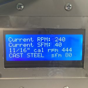
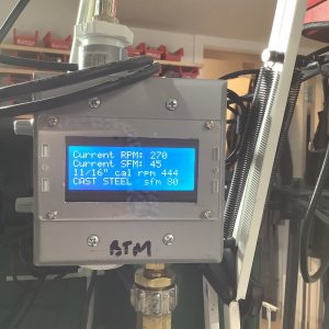
Found a product called the Tachulator that makes them with optical sensors and both with and without a built in SFM calculation feature. There are a few resellers in the states like http://www.mkctools.com/tachulator.htm and little machine shop. I was surprised to find with some digging that they are made in Toronto by http://www.trexon.com/ .
Has any one bought or seen one in person before? I emailed the address on the trexon page but didn’t get a response.
I have bought and tried the cheap Hall effect ones and not been overly impressed.
Found a product called the Tachulator that makes them with optical sensors and both with and without a built in SFM calculation feature. There are a few resellers in the states like http://www.mkctools.com/tachulator.htm and little machine shop. I was surprised to find with some digging that they are made in Toronto by http://www.trexon.com/ .
Has any one bought or seen one in person before? I emailed the address on the trexon page but didn’t get a response.