Actually, that is not true. As a guy who has actually done FEA in his previous life, I can assure you that this would be a very complex and difficult FEA project requiring a huge number of tests to refine the parameters for an appropriate model. If it can be done at all, I think it might even be a worthy subject for a PhD Thesis. FEA is inherently more suitable to modelling materials that have predictable stress strain characteristics. Cast iron is an inherently more difficult material to model. Its variability alone is a formidable challenge. That's before we combine it with other materials which increase the complexity and the difficulty of the analysis.
As a guy who has never done FEA, even I can certainly appreciate this statement. Multiple levels above my pay grade.
But FWIW I wasn't assuming FEA to completely analyse a T-nut + table model to failure state. I was assuming (hoping) the loads could be set progressively, 40%, 50%, 70%, whatever... in order to get a qualitative feel for resultant stress patterns & particularly where hot zones are developing. ie. leveraging on the progressive load stress contour snapshots, bypassing the complications of 98% load to 100% failure interval. I would think 'from accross the room' these snapshots could provide SOME useful information, especially if they were normalized to the same apples-to apples partial load & varied differnt clamp / T-nut / clamping shapes & layout arrangements.
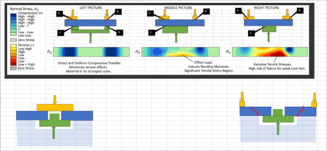
We started out talking about conventional T-nuts, and that developed to improvements to vise clamping specifically. The CWRET clamp (for lack of better label) is not appreciably different than the Bison clamp on the top side of table in terms of load layout and contact area. Looks like a bit different dimensionally & bolt axis location, which could influence things one way or another, but we didnt get that far. What is different (as I understand it) is the accompanying CWRET T-nut which aligns its outboard contact lip to the top-side clamp lip. This makes intuitive sense because it puts the table element in compression at the outboard contact point which is where we want cast iron to be. Under the lip of the VISE, seems like CWRET = Bison = pure compression on the table. So my unsubstantiated gut feel is the CRWRET assembly is better than the Bison (only) because of the associated T-nut. How would I quantify or prove that? I can't, at least without better tools at my disposal. So I pointed out the more extreme end of the spectrum which happens to be very common general mill table clamping arrangements like notched pillar + strap clamps or Bessey clamps as examples. Here we have less choice (or no choice) in the arrangement matter depending on how the clamp is orientated to a part in general. If the Bessy is aligned to a vise lip like CWRET or Bison, its outer topside contact line is much further outboard relative to T-nut extent. Which is a slightly worse case than the Bison. But putting vise clamping aside, a much worse scenario is a clamping arrangement, where Bessey clamp is prientated perpendicular to T-slots. Now its trying pulling the T-nut straight out of the T-slot no benefit of any overlapping compressive restraint area anywhere. And yet these clamps are used every day WITHIN SOME SAFE LEVEL OF BOLT TENSION. My guess is this type of clamping is where the actual tear-out pictures originate from +/- excessive bolt tension values & casting variations which of course is very important, but even hrder to pin down.
So maybe a picture like this clarifies where I am coming from. We could come up with all sorts of interesting clamping fixtures but I tried to superimposethe 3 clamping arrangements discussed ones side by each. Its just AI puke in terms of stress contours, but maybe gets the point accross. And because we seem to have a knack of me drawing the elephants trunk & its somehow interpreted as its tail, I'll try to be more specific. This is a cartoon cross section looking at the front of the mill table via cross section through the table element lip where it also intersects the T-nut below & vise support above. The solid blue is the upper T-slot lip. Light blue area is just recognizing there is more table thickness below the lip, but not really helping matters in terms of failure or providing strength in this orientation. Green is T-nut object. Yellow is topside loading areas. Hopefully it makes sense.
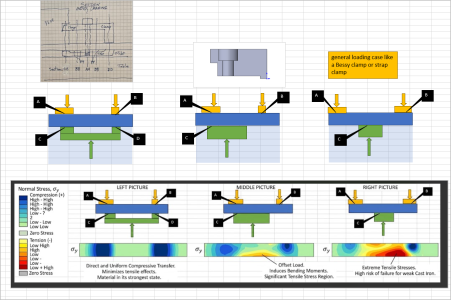
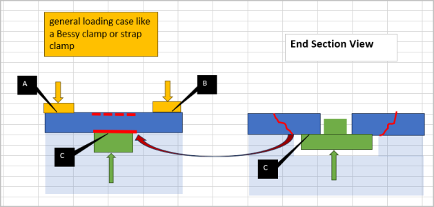
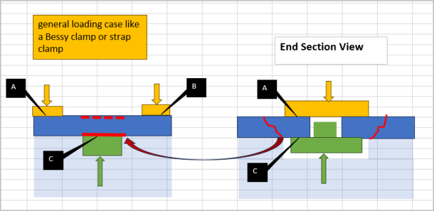
This is harder for me to draw, but attempting cross sections now looking from the end of the table, down the axis of T-slot.
Left: through A-C or B-D on CWRET clamp. Shows the same 'good' compressive loading arrangement as far as the blue table is concerned. I dont think the middle area of the top clamp over the open T-slot clamp contibutes anything, but thats a different sub-topic
Right: like a worst case Bessey arrangement. The yellow upper contact areas are far away, or at least outside where we know the fracture occurs. Its a straight pull-out mode.
Middle = Bison: I'm not sure how to draw or interpret so left it blank. My gut says if we slide the cross section from left to right we would see pure compression (exactly like CWRET A-C) but then it would decay to something else. And that something else is complicated because of the length of green T-nut as it relates to outboard contact lip B. But maybe thatswhere FEA would fill in color

I think what was getting completely lost in translation is superimposing the 2 sections as it pertains to stress crack. Grasping at straws again.
The (right) red squiggly is the familiar & intuitive stress crack originating at T-slot corner viewing from the end of the table. I guess it must equate to (left) a line along the table lip?