• Scam Alert. Members are reminded to NOT send money to buy anything. Don't buy things remote and have it shipped - go get it yourself, pay in person, and take your equipment with you. Scammers have burned people on this forum. Urgency, secrecy, excuses, selling for friend, newish members, FUD, are RED FLAGS. A video conference call is not adequate assurance. Face to face interactions are required. Please report suspicions to the forum admins. Stay Safe - anyone can get scammed.
  • The 2026 Calgary Area Meetup is set for Saturday May 30th at 10am. The signup thread is here! Robinhood has graciously offered to host the meetup again this year. Please note that you MUST RSVP to the notice linked above if you wish to come.

Shop T-nuts

Shop
As I mentioned, this would be small potatoes for FEA but unfortunately I don't know anyone. Better yet, it could be directed to evaluate the original questions of clamping geometry & styles

IMO you have been in discussion with someone ( @Susquatch ) that knows, understands, and is more educated in FEA and mechanical engineering than 90% of Professional Engineers.

Craig P. Eng. (retired)
 
IMO you have been in discussion with someone ( @Susquatch ) that knows, understands, and is more educated in FEA and mechanical engineering than 90% of Professional Engineers.
Maybe he has some contacts who can generate some FEA results. I for one would be interested.
 
In the preceeding posts I tried to reduce the loading picture into simpler block elements. If/as we agreed on the basics, then we add in additional features approaching the full picture. Looks like that was another bad plan. Hopefully this clarifies where I was coming from, if not, oh well.

Your more complete model with black "anchors" is better and makes more sense to me. I believe I can see now where you were coming from.

It doesn't change my responses though.

As I mentioned, this would be small potatoes for FEA but unfortunately I don't know anyone.

Actually, that is not true. As a guy who has actually done FEA in his previous life, I can assure you that this would be a very complex and difficult FEA project requiring a huge number of tests to refine the parameters for an appropriate model. If it can be done at all, I think it might even be a worthy subject for a PhD Thesis.

FEA is inherently more suitable to modelling materials that have predictable stress strain characteristics. Cast iron is an inherently more difficult material to model. Its variability alone is a formidable challenge. That's before we combine it with other materials which increase the complexity and the difficulty of the analysis.

The difficulty is less in the FEA mechanics and more in getting the failure prediction to mean anything for a highly variable brittle material in a mixed environment alongside steel in a non-elastic yielding condition.

To do that requires testing and model validation. So we do the testing, and then we discover that another batch of the same cast iron behaves differently, or that it has more or less porosity, or a different graphite flake structure, or or or. And then we start all over again. It reminds me of the video posted recently of a whole factory operating over many years to produce an equation.

I know that you have grown tired of this discussion. I feel badly about that. Rather than going back and forth so much without much progress, can you tell us what it is that you are trying to understand or learn?
 
Actually, that is not true. As a guy who has actually done FEA in his previous life, I can assure you that this would be a very complex and difficult FEA project requiring a huge number of tests to refine the parameters for an appropriate model. If it can be done at all, I think it might even be a worthy subject for a PhD Thesis. FEA is inherently more suitable to modelling materials that have predictable stress strain characteristics. Cast iron is an inherently more difficult material to model. Its variability alone is a formidable challenge. That's before we combine it with other materials which increase the complexity and the difficulty of the analysis.
As a guy who has never done FEA, even I can certainly appreciate this statement. Multiple levels above my pay grade.

But FWIW I wasn't assuming FEA to completely analyse a T-nut + table model to failure state. I was assuming (hoping) the loads could be set progressively, 40%, 50%, 70%, whatever... in order to get a qualitative feel for resultant stress patterns & particularly where hot zones are developing. ie. leveraging on the progressive load stress contour snapshots, bypassing the complications of 98% load to 100% failure interval. I would think 'from accross the room' these snapshots could provide SOME useful information, especially if they were normalized to the same apples-to apples partial load & varied differnt clamp / T-nut / clamping shapes & layout arrangements.

We started out talking about conventional T-nuts, and that developed to improvements to vise clamping specifically. The CWRET clamp (for lack of better label) is not appreciably different than the Bison clamp on the top side of table in terms of load layout and contact area. Looks like a bit different dimensionally & bolt axis location, which could influence things one way or another, but we didnt get that far. What is different (as I understand it) is the accompanying CWRET T-nut which aligns its outboard contact lip to the top-side clamp lip. This makes intuitive sense because it puts the table element in compression at the outboard contact point which is where we want cast iron to be. Under the lip of the VISE, seems like CWRET = Bison = pure compression on the table. So my unsubstantiated gut feel is the CRWRET assembly is better than the Bison (only) because of the associated T-nut. How would I quantify or prove that? I can't, at least without better tools at my disposal. So I pointed out the more extreme end of the spectrum which happens to be very common general mill table clamping arrangements like notched pillar + strap clamps or Bessey clamps as examples. Here we have less choice (or no choice) in the arrangement matter depending on how the clamp is orientated to a part in general. If the Bessy is aligned to a vise lip like CWRET or Bison, its outer topside contact line is much further outboard relative to T-nut extent. Which is a slightly worse case than the Bison. But putting vise clamping aside, a much worse scenario is a clamping arrangement, where Bessey clamp is prientated perpendicular to T-slots. Now its trying pulling the T-nut straight out of the T-slot no benefit of any overlapping compressive restraint area anywhere. And yet these clamps are used every day WITHIN SOME SAFE LEVEL OF BOLT TENSION. My guess is this type of clamping is where the actual tear-out pictures originate from +/- excessive bolt tension values & casting variations which of course is very important, but even hrder to pin down.

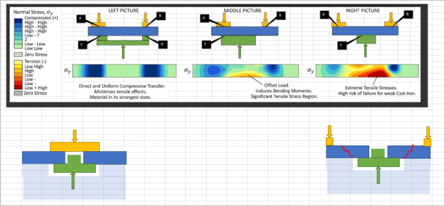
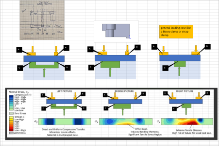
So maybe a picture like this clarifies where I am coming from. We could come up with all sorts of interesting clamping fixtures but I tried to superimposethe 3 clamping arrangements discussed ones side by each. Its just AI puke in terms of stress contours, but maybe gets the point accross. And because we seem to have a knack of me drawing the elephants trunk & its somehow interpreted as its tail, I'll try to be more specific. This is a cartoon cross section looking at the front of the mill table via cross section through the table element lip where it also intersects the T-nut below & vise support above. The solid blue is the upper T-slot lip. Light blue area is just recognizing there is more table thickness below the lip, but not really helping matters in terms of failure or providing strength in this orientation. Green is T-nut object. Yellow is topside loading areas. Hopefully it makes sense.
1788971529332.png

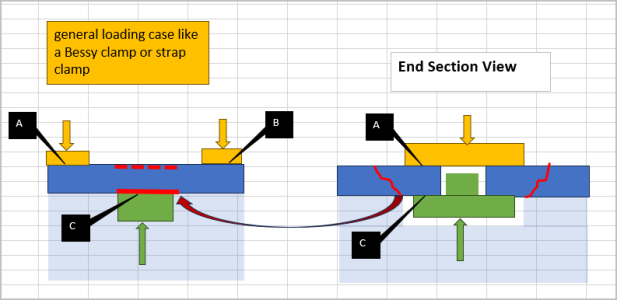
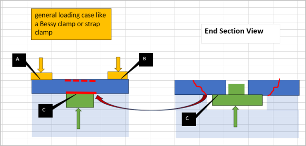
This is harder for me to draw, but attempting cross sections now looking from the end of the table, down the axis of T-slot.
Left: through A-C or B-D on CWRET clamp. Shows the same 'good' compressive loading arrangement as far as the blue table is concerned. I dont think the middle area of the top clamp over the open T-slot clamp contibutes anything, but thats a different sub-topic
Right: like a worst case Bessey arrangement. The yellow upper contact areas are far away, or at least outside where we know the fracture occurs. Its a straight pull-out mode.
Middle = Bison: I'm not sure how to draw or interpret so left it blank. My gut says if we slide the cross section from left to right we would see pure compression (exactly like CWRET A-C) but then it would decay to something else. And that something else is complicated because of the length of green T-nut as it relates to outboard contact lip B. But maybe thatswhere FEA would fill in color

1788976625416.png

I think what was getting completely lost in translation is superimposing the 2 sections as it pertains to stress crack. Grasping at straws again.
The (right) red squiggly is the familiar & intuitive stress crack originating at T-slot corner viewing from the end of the table. I guess it must equate to (left) a line along the table lip?
1789050312488.png
 

Attachments

  • 1788974484471.png
    1788974484471.png
    352 KB · Views: 7
  • 1788974773452.png
    1788974773452.png
    29 KB · Views: 24
Last edited:
FEA is inherently more suitable to modelling materials that have predictable stress strain characteristics. Cast iron is an inherently more difficult material to model. Its variability alone is a formidable challenge. That's before we combine it with other materials which increase the complexity and the difficulty of the analysi
You might appreciate what goes on attempting to model subsurface rock mechanics in the energy industry. Now throw in multiple laminations of highly variable Mother Nature strata. Different thicknesses, different strength properties, post depositional changes, different fluid saturations, pressure variations (pore vs injection vs withdrawl), temperature deviations.... And because its buried deep downstairs where you cant touch it & visualized through interpretive mapping, much of it using core samples representing a miniscule % volume of interest.... its art + science (and sometimes wishful thinking). I've been reading some books that discuss subsurface nuclear test blasts in the 50's. Now that must have been interesting in terms of containment calculations.
 
You might appreciate what goes on attempting to model subsurface rock mechanics in the energy industry. Now throw in multiple laminations of highly variable Mother Nature strata. Different thicknesses, different strength properties, post depositional changes, different fluid saturations, pressure variations (pore vs injection vs withdrawl), temperature deviations.... And because its buried deep downstairs where you cant touch it & visualized through interpretive mapping, much of it using core samples representing a miniscule % volume of interest.... its art + science (and sometimes wishful thinking).

Yes, I can definitely appreciate that. It would be complicated and difficult. Definitely not something I have any experience with. @CWret had a rock drilling company and might be able to comment.

Of course, the needs are very different and I'd have no idea about what would be expected in terms of reasonable outputs. I'd guess that it depends on what they do with it. Who knows, maybe wishfull thinking is actually good enough! I think I'd very much enjoy listening to someone tell me how they do it, why they do it, and how much it has improved the business.
 
Not wanting to expand this new rabbit hole about rock mechanics but I’d like to add a couple comments:
@CWret had a rock drilling company and might be able
Certainly all of the variables that @PeterT mention are to be considered during mine design and those inconsistencies are much like us dealing with the flaws in mill table cast iron. Identifying, quantifying, evaluating, measuring and compiling all that information can be a daunting task when designing underground openings. I might add that the big variable that Peter omitted is tectonic stresses. Mining rock mechanics uses an integrated approach combining empirical methods, numerical modeling (including FEA) and field monitoring since individually they have limitations. Mining engineers avoid the FEA pit falls by also using and including FDM and DEM (Finite Difference Method and Distinct Element Method). Monitoring/measuring movement is a vital part of mine design/safety.
I think I'd very much enjoy listening to someone tell me how they do it,
- here’s an example - this is from 50+ years ago. I worked with a grad student doing his PhD on rock mechanics. His thesis was measuring in situ rock mass stresses. The focus was developing/improving measurement of in situ rock stress by: installing a strain gauge at the end of a 3” diameter drill hole (end of the hole was ground flat and then a stain gauge was epoxy attached); next a diamond drilled hole (usually +9” diameter) was over cored on the 3” hole. This procedure isolated the 3” hole so it could freely move and reveal in situ rock stress (via the stain gauge movement).
 
As a guy who has never done FEA, even I can certainly appreciate this statement. Multiple levels above my pay grade.

But FWIW I wasn't assuming FEA to completely analyse a T-nut + table model to failure state. I was assuming (hoping) the loads could be set progressively, 40%, 50%, 70%, whatever... in order to get a qualitative feel for resultant stress patterns & particularly where hot zones are developing. ie. leveraging on the progressive load stress contour snapshots, bypassing the complications of 98% load to 100% failure interval. I would think 'from accross the room' these snapshots could provide SOME useful information, especially if they were normalized to the same apples-to apples partial load & varied differnt clamp / T-nut / clamping shapes & layout arrangements.

It's a worthy goal but I don't think it is realistic to think we hobbiests will ever get there for our T-Nut application. It's too much research and testing for the value we might get out of it.

We started out talking about conventional T-nuts, and that developed to improvements to vise clamping specifically. The CWRET clamp (for lack of better label) is not appreciably different than the Bison clamp on the top side of table in terms of load layout and contact area. Looks like a bit different dimensionally & bolt axis location, which could influence things one way or another, but we didnt get that far. What is different (as I understand it) is the accompanying CWRET T-nut which aligns its outboard contact lip to the top-side clamp lip. This makes intuitive sense because it puts the table element in compression at the outboard contact point which is where we want cast iron to be. Under the lip of the VISE, seems like CWRET = Bison = pure compression on the table. So my unsubstantiated gut feel is the CRWRET assembly is better than the Bison (only) because of the associated T-nut. How would I quantify or prove that? I can't, at least without better tools at my disposal. So I pointed out the more extreme end of the spectrum which happens to be very common general mill table clamping arrangements like notched pillar + strap clamps or Bessey clamps as examples. Here we have less choice (or no choice) in the arrangement matter depending on how the clamp is orientated to a part in general. If the Bessy is aligned to a vise lip like CWRET or Bison, its outer topside contact line is much further outboard relative to T-nut extent. Which is a slightly worse case than the Bison. But putting vise clamping aside, a much worse scenario is a clamping arrangement, where Bessey clamp is prientated perpendicular to T-slots. Now its trying pulling the T-nut straight out of the T-slot no benefit of any overlapping compressive restraint area anywhere. And yet these clamps are used every day WITHIN SOME SAFE LEVEL OF BOLT TENSION. My guess is this type of clamping is where the actual tear-out pictures originate from +/- excessive bolt tension values & casting variations which of course is very important, but even hrder to pin down.

So maybe a picture like this clarifies where I am coming from. We could come up with all sorts of interesting clamping fixtures but I tried to superimposethe 3 clamping arrangements discussed ones side by each. Its just AI puke in terms of stress contours, but maybe gets the point accross. And because we seem to have a knack of me drawing the elephants trunk & its somehow interpreted as its tail, I'll try to be more specific. This is a cartoon cross section looking at the front of the mill table via cross section through the table element lip where it also intersects the T-nut below & vise support above. The solid blue is the upper T-slot lip. Light blue area is just recognizing there is more table thickness below the lip, but not really helping matters in terms of failure or providing strength in this orientation. Green is T-nut object. Yellow is topside loading areas. Hopefully it makes sense to.

This is harder for me to draw, but attempting cross sections now looking from the end of the table, down the axis of T-slot.
Left: through A-C or B-D on CWRET clamp. Shows the same 'good' compressive loading arrangement as far as the blue table is concerned. I dont think the middle area of the top clamp over the open T-slot clamp contibutes anything, but thats a different sub-topic

I believe it only adds nut stiffness in the X axis. Even that is probably very little because of the threaded hole which would minimize bending and maximize yielding at the hole - causing a "V" shaped nut.

Right: like a worst case Bessey arrangement. The yellow upper contact areas are far away, or at least outside where we know the fracture occurs. Its a straight pull-out mode.

Yup, not good.

Middle = Bison: I'm not sure how to draw or interpret so left it blank. My gut says if we slide the cross section from left to right we would see pure compression (exactly like CWRET A-C) but then it would decay to something else. And that something else is complicated because of the length of green T-nut as it relates to outboard contact lip B. But maybe thatswhere FEA would fill in color

Again, very difficult to do. And without validation testing virtually guaranteed to be wrong. I truly believe that this is the realm of engineering experience. An educated, experienced, and capable mind can see what a computer model cannot be easily programmed to see. It's easy to assume it is correct just because a computer model spits it out. But I'll take experience over a program written by an unknown author every single time. That's what makes validation in areas like this so important. If the output doesn't reflect reality, it isn't worth squatt.

I think what was getting completely lost in translation is superimposing the 2 sections as it pertains to stress crack. Grasping at straws again.
The (right) red squiggly is the familiar & intuitive stress crack originating at T-slot corner viewing from the end of the table. I guess it must equate to (left) a line along the table lip?


Yes. But again, we are mostly interested in understanding what happens and preventing it. In this case, that doesn't depend on expanding the model or the thinking.

We know enough to know how to move forward.
 
Today I tested the torque levels of my 6x M10x1.5 Bison clamp SHCS which thread into better fitting T-nuts using with my (recent birthday present) fancy-schamcy Wera torque wrench. Thus far I have been self-limiting myself to reasonable non-gronk pull on 4-5" long hex key, counting on my wimpy wrists & short lever arm to limit torque. They unloosened at average 12 N-m per bolt, one was 16 N-m. Assuming breakaway loosening like this is accurate? The vise has never moved on me with this kind of setting so I assume should be ok unless I incur some heavier interrupted milling job. So I set the wrench for 15 N-m = 11 ft-lbs which works out to 1500-1800 lb axial on this size fastener depending on the lubrication or lack of (according to AI). About 1/3 value @Susquatch was calculating as reasonably safe from CI tearout perspective.
 
They unloosened at average 12 N-m per bolt, one was 16 N-m. Assuming breakaway loosening like this is accurate?

Good info Peter.

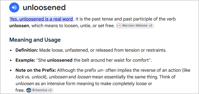
What is "unloosened"? LOL!

A good rule of thumb is that loosening torque is usually about 75% +/- 10% of tightening torque.

Corroded connections can vary significantly.
 
Back
Top