• Scam Alert. Members are reminded to NOT send money to buy anything. Don't buy things remote and have it shipped - go get it yourself, pay in person, and take your equipment with you. Scammers have burned people on this forum. Urgency, secrecy, excuses, selling for friend, newish members, FUD, are RED FLAGS. A video conference call is not adequate assurance. Face to face interactions are required. Please report suspicions to the forum admins. Stay Safe - anyone can get scammed.

Small shaft repair options?

You can get threaded rod at PA. Cheap too. I got it at 50% off on sale.

I made multiple pull rods for my mills. The trick is to thread not single point - as the thread is small and speed would need to be fast - but just place the rod in the collet in the tailstock and place the die in the chuck. Run forward, run reverse - done. Takes like few minutes.

12" is quite short, you don't have to worry too much about the part whiplash too much - for longer stuff you need a follow rest for sure or similar setup.

Overall to make a new part like on picture from some scrap I have to precise dimensions is like maybe 2h. Maybe faster if in race mode ;) To weld and fix probably over an hour, maybe 2 as well. If its a wear part and you expect to go through multiples, make 2, will take a bit longer then 1, maybe 3h.
 
PEr my last response to you, I had posted the schematic earlier in the thread. Since you didnt seem to notice this, here it is again

Yes actually, I did notice the diagram. Even without the parts unidentified, I think I understand the distinction & purpose of spacers, bearings and nuts. What was confusing was your description. Apparently all the components are 'at the end of shaft'. Early on I thought red arrow parts might be bushings integral to the end of the drum & possibly a typo. Exploded views are nice but don't show parts in-situ. It may be obvious to you but not to someone else. Good luck with your project.

There are identical bearings at each end of this shaft with an id that is a slightly loose press fit. So the two drums slip fit on the shaft and two spacers are added, one at each end of the shaft. The two nuts thread on at each end of the shaft until it draws the bearings, spacers and drums together tightly to rotate with the rotation of the shaft
 

Attachments

  • EDT-2022-01-25 12.07.59 PM.webp
    EDT-2022-01-25 12.07.59 PM.webp
    24.9 KB · Views: 1
PEr my last response to you, I had posted the schematic earlier in the thread. Since you didnt seem to notice this, here it is again

Yes actually, I did notice the diagram. Even without the parts unidentified, I think I understand the distinction & purpose of spacers, bearings and nuts. What was confusing was your description. Apparently all the components are 'at the end of shaft'. Early on I thought red arrow parts might be bushings integral to the end of the drum & possibly a typo. Exploded views are nice but don't show parts in-situ. It may be obvious to you but not to someone else. Good luck with your project.

There are identical bearings at each end of this shaft with an id that is a slightly loose press fit. So the two drums slip fit on the shaft and two spacers are added, one at each end of the shaft. The two nuts thread on at each end of the shaft until it draws the bearings, spacers and drums together tightly to rotate with the rotation of the shaft
I gotta be honest, your wording and tone comes across very accusatory and condescending. I'm obviously a newbie trying to explain this. Why not help a guy out rather than come across in a condescending fashion?
 
You can get threaded rod at PA. Cheap too. I got it at 50% off on sale.

I made multiple pull rods for my mills. The trick is to thread not single point - as the thread is small and speed would need to be fast - but just place the rod in the collet in the tailstock and place the die in the chuck. Run forward, run reverse - done. Takes like few minutes.

12" is quite short, you don't have to worry too much about the part whiplash too much - for longer stuff you need a follow rest for sure or similar setup.

Overall to make a new part like on picture from some scrap I have to precise dimensions is like maybe 2h. Maybe faster if in race mode ;) To weld and fix probably over an hour, maybe 2 as well. If its a wear part and you expect to go through multiples, make 2, will take a bit longer then 1, maybe 3h.
I dont understand where threaded rod could be used here.

The shaft finished OD is supposed to be 15mm +/- some small tolerance. 3/4" on each end needs to be turned down to 1/2" and threaded for 1/2-20 (or 1/2-13 as janger suggested). Thats it.

I cant imagine this is a 2 hour job per shaft, is it?
 
I dont understand where threaded rod could be used here.

The shaft finished OD is supposed to be 15mm +/- some small tolerance. 3/4" on each end needs to be turned down to 1/2" and threaded for 1/2-20 (or 1/2-13 as janger suggested). Thats it.

I cant imagine this is a 2 hour job per shaft, is it?

I think they are using threaded rod as raw material.

It is about 2h job or so - done it recently. Cut rod down to 12mm, thread both ends 12x1.5 Main difference here is playing around with bearing surfaces vs. longer rod.

Maybe I am missing something? It feels it is a standard rod holding a roller, threaded from two sides with two bearings to support such roller.
 
The entire rod doesnt need to be cut down to 15mm. The 15mm nominal size of teh 'ground drill rod' out of the box works (apparently). Just the ends need to be turned down and threaded.
 
The entire rod doesnt need to be cut down to 15mm. The 15mm nominal size of teh 'ground drill rod' out of the box works (apparently). Just the ends need to be turned down and threaded.

Well, if you only need to do the ends what is the big deal? Maybe just over 1h of work? Is making the stuff for bearings an issue - just get it close and then you can use emery cloth - if you make it "too loose" you can just use Loctite to "cheat". Threading can be the hardest part - just use dies for small thread, 1/2-20 is easier then 1/2-13. Hold die in the chuck, preferably hex, hold rod in collet chuck and do it, or have a die holder and rotate the shaft - quick and easy - threads are not "funky".
 
I gotta be honest, your wording and tone comes across very accusatory and condescending. I'm obviously a newbie trying to explain this. Why not help a guy out rather than come across in a condescending fashion?

Sorry you feel that way. I'm not sure how asking clarifying questions is accusatory or condescending, especially when it might dictate a particular course of action. I think I have been helpful suggesting remedial action as the assembly has become more clear. When I read below I got a vibe like, hey dummy, read the post, I already explained it once. Lets call it an internet miscommunication & move on.

Since you didnt seem to notice this, here it is again
 
Maybe I should leave well enough alone, but here goes. If this sketch still doesn't represent the assembly then I guess @calgaryguy can comment or pass or leave it to whoever assists when the time comes. The devil is in the details here but if the tightening force goes nut > washer > inner bearing race > spacer > drum, it kind of makes logical sense. All these components spin, the outer bearing race stays put, balls go round & round. I'm not sure if I have the casting housing correct in how it supports bearing OD, maybe it has a flange or stop. If this isn't the case then ignore what follows.

What has mystified me all along is how substantial wear on the shaft occurred under the inner bearing race. Was shaft OD / bearing ID undersize to begin with? I could see if it was a fixed bushing but that's a lot of relative slip given the bearing race is free to spin, no?. Maybe the washer was replaced & contacting both inner & outer races & causing partial bearing spin? No wear on bearing housing ID was mentioned. I'll leave it at this. Good luck.
 

Attachments

  • SNAG-1-26-2022 000.jpg
    SNAG-1-26-2022 000.jpg
    41.1 KB · Views: 8
The threads are both RH on each end. No need for LH threads. Got my drill rod Thursday from KBC. $52 (all in, frieght, tax, etc) for a 1m length of 15mm ground drill rod. Checking with a mitu mic shows the diameter to be very uniform as expected. I went with KBC as MSM in YYC doesnt carry anything larger than 3mm ground drill rod and their price to have something similar brought in was considerably more than KBC.
 
I picked up this on kijiji used for $100 last year, so not a problem. Of course I've already had to buy 3-4 dies that werent in the set for odd sizes. I got tired of junky T&D sets with poor quality tap and die handles, etc. This set is vastly superior in quality to the cheapies I've owned in the past.

View attachment 20278
You did well , those are nort of $400.00 on the Snapon truck , I have the same set
 
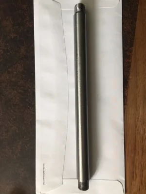
Finished shaft:

1646756159182.png


I ended up using a 'floating' tailstock die holder to do the threads instead of single point threading them.

My neighbours CX709 lathe has metric dials. This was my first lathe project since high school 30-ish years ago, so between re-familiarizing myself with 'touching off', 'zeroing' my dials, and the switching back and forth between metric and imperial (my mics are imp) in my head was confusing and I screwed up my first two attempts. Good thing the 15mm drill rod I got from KBC was 3 feet, lol.

I should add that my neighbour had a bag of the standard 'blue' (BusyBee/KMS, etc) brazed on carbide tools that came with his used CX709 which were all size '8' (1/2" shank) and he was using a jury rigged set of shims to set them to the lathe centerline. This didnt look right to me, so I did some reading and it seemed that I needed size '10' tools (5/8" shank). A quick trip to KMS and $30 bucks later and I had teh correct tooling to do the work without screwing around with a bunch of shims.
 
Last edited:
I

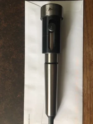
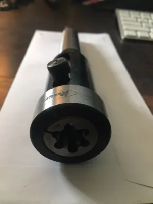
View attachment 21781View attachment 21782

The MT3 taper needed to be 'set' in the tailstock quite firmly for it not to spin while threading. This was one of teh screwups I encountered. Also, I should have remembered to chamfer the ends of teh shaft after turning the shoulders down to allow the die to bite in more easily. Lessons learned for next time.

I confess that I am shocked that it spun. Usually tapers with the tang tip do not (actually can not) spin except for a few degrees when the tang catches.

And before anyone jumps on me, yes I know that's not the purpose of the tang nor good practice, nor would I ever use it that way.

It is just that I am shocked and find myself wondering how that is possible.
 
I


I confess that I am shocked that it spun. Usually tapers with the tang tip do not (actually can not) spin except for a few degrees when the tang catches.

And before anyone jumps on me, yes I know that's not the purpose of the tang nor good practice, nor would I ever use it that way.

It is just that I am shocked and find myself wondering how that is possible.

I spin my MT2 tailstock tapers all the time, it's quite annoying. Not all tailstock spindles provide a means to utilize a tang.
 
Back
Top