• Spring 2024 meetup in Calgary - date Saturday, April 20/2024. discussion Please RSVP Here to confirm and get your invitation and the location details. RSVP NOW so organizers can plan to get sufficient food etc. It's Tomorrow Saturday! you can still RSVP until I stop checking my phone tomorrow More info and agenda
  • We are having email/registration problems again. Diagnosis is underway. New users sorry if you are having trouble getting registered. We are exploring different options to get registered. Contact the forum via another member or on facebook if you're stuck. Update -> we think it is fixed. Let us know if not.
  • Spring meet up in Ontario, April 6/2024. NEW LOCATION See Post #31 Discussion AND THE NEW LOCATION

SM1340 Change Gears

RobinHood

Ultra Member
Premium Member
My Standard Modern 13X40 lathe is all metric. I want to be able to cut inch threads as well. It did not come with the change gears. Called SM to see if they are available: YES. Great, how much? $$$$$$$$s! OK thanks, I'll pass for that price. Off I went to make my own. This time I had my mill and universal indexer. So I made a few gears, the most important one being 127T transposing gear because it is the lowest common denominator for the 254mm/1in ratio. I have enough room on my lathe for such a big gear as long as my change gears were all DP24s , 14.5 PA.

Oh, wait, I have no arbour for my gear cutter; so I made one out of an old lawn mover spindle
DSC03163.JPG

I used mild steel plate, 1/2 thick, and rough cut all the gear blanks with an appropriately sized hole saw and turned to size after. Except for the 127T one, which I rough cut on the band saw into an octagon shape and turned to size on the lathe.

My first gear was the 45T in the set - if I mess up, then he would be the least amount of work to redo.
DSC03205.JPG

Here is another view
DSC03206.JPG

And here is the final product with some of the calculations I did to create it
DSC03209.JPG

As Tom Lipton says: "Rinse and Repeat" for the others. The 127T gear is special since 127 is a prime number and there is not way for either "direct" or "indirect" division of the 360* circle. But since I have an Universal Dividing Head with all its change gears, I was able to use the "differential indexing" method to divide the 360* circle into 127 equal parts.
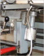
Here is the set-up
DSC03219.JPG

And a view of the dividing head's change gears. In a nutshell here is how "Differential Indexing" works mechanically: the indexing plate is on a shaft which is linked via the change gears to the dividing head's spindle. As you rotate the indexing lever the appropriate # holes along the indexing plate, the dividing head spindle moves. Also - through the gears on the back - the shaft upon which the indexing plate sits moves; therefore the indexing plate moves - hence the term "differential" (that is what's different from "direct' or "indirect" indexing). Kind of hard to describe; easier to grasp when you see it in action and quite a clever thing. Kudos to the engineer that came up with it!
DSC03221.JPG

After many hours of cutting, here they are. I ran them on my tool & cutter grinder for a nice surface finish - because I had no surface grinder at the time. All were engraved with the respective # teeth on the pantograph.

A close-up of the surface finish
IMG_0135.JPG

Here is the set-up for the engraving process using the Deckel Pantograph
IMG_0143.JPG

And all done
IMG_0145.JPG

And two in use on the SM1340 (here they were not surface ground or engraved yet).
DSC03224.JPG
 

PeterT

Ultra Member
Premium Member
Very impressive!
Now I'm intrigued - legend has it that Asia lathes like my Taiwan 14x40 & similar flavors were 'heavily based on' (some say made casting patterns for) Standard Moderns. Can we see some pics of the lathe sometime? I've never actually seen them up close personally.

So did the threading lead screw & half nuts also have to be changed out to cut IMP threads? I've never totally understood this, if it can be dealt with in change gears alone, a function of the lathe, or only certain pitches available, or some are close but not exact...
 

RobinHood

Ultra Member
Premium Member
I have heard that as well; there are certainly a lot of similarities...

Here is one after we just got it home, still on the trailer
DSC02868.JPG

A close up of the business end
DSC02869.JPG

Taper attachment and Acu-Rite DRO scales
DSC02871.JPG

After some cleaning...
DSC02896.JPG

Here she is, all done, including a little goose neck LED work light (the pic is really too close, but that's all I have right now)
DSC03130.JPG


Metric/Inch conversion (btw, one can also go Inch/Metric, the principle is the same, the ratios change)

The lead screw, half nut and the feed box all stay the same.
Below is a table from the manual that gives me the change gear "B" (the ones I made) I have to mesh with the transposing gear "A" (the 127T one I made) and the feed box setting in order to cut the required inch thread.

upload_2017-4-1_8-46-30.png
This table could be expanded to allow for Module and Diametral pitches as well - just would need to make more change gears "B".

As far as accuracy of the threads: they are theoretically 100% accurate because of the 127T transposing gear. There are exactly 254mm in 1 inch or 127mm in 0.5in. The 127T gear runs on the same shaft coupled to the 48T gear (see diagram above), so they both turn at the same rpm. Any time you have two gears on the same shaft coupled, you create/change the ratio of the whole gear train. Any idler gears in a gear train do not have any influence on the overall ratio. In the diagram above, the 45T and 60T idler gears are just "space fillers" and could be replaced with a chain and the ratio of the gear train would stay exactly the same. The change gear "B" sits on the input shaft to the feed box and will mesh with the change gear "A". The overall ratio of the whole gear train is determined by the 24T head stock gear, the coaxial 48T/127T transposing gear, and the feed box input shaft gear (aka change gear "B").

Ignoring the 127T transposing gear for a moment, the basic gear train ratio is a follows 24T (headstock) to 45T (idler) to 60T (idler) to 48T (feed box). This can can be simplified to 24T/48T = 0.5. When we put the 127T gear into the set, on the same shaft as the other 48T grear (see diagram), we change the ratio to 127/0.5 = 254 ===> how convenient, there are 254mm/1in.

They did the rest of the math for us, phew, and gave us a nice little table, see above...

Sorry, this got a little long. It's much easier to understand when you see it in action.

So as long as my metric lead screw does not have any/too much wear, any length of SAE thread can be cut accurately.

I do have to keep the half nut engaged at all times, when I cut Inch threads. It's like on a SAE lathe cutting metric threads: leave the half nut engaged and use spindle fwd/rew to move the tool - if one goes by the book.... But I don't...

Actually, I don't leave them engaged in either case: when I thread SAE, I open the half nut lever at the end of the cut and watch how far the thread dial moves after I stop the lathe (I don't have a brake or clutch on this machine, so the spindle rolls over a few revs before it comes to rest). I reverse the lathe and re-engage when the same mark on the thread dial comes by (that is important!). Joe Pieczynski on YouTube has a great explanation of the process. I also always try to thread away from a shoulder if at all possible (left or right hand thread). Again, see Joe Pie's video.

Hope that helps explain things a bit.
 

Alexander

Ultra Member
Administrator
Great post. I only ever tried diferential indexing at sait during my apprenticeship. It is time consuming to set up and tricky to hit exactly the right whole all 127 times. You must be very tallented. Great explination of how it all works.
 

PeterT

Ultra Member
Premium Member
Great explanation on the threading gears. And nice lathe recondition. Well, I'd say 'some' things are similar to mine, but a lot of things are quite different & (yours) looks beefier in many respects.
- re taper turning, what's the procedure or underlying mechanism that disengages the cross slide nut / lead screw assembly? I've heard some you unscrew a nut & others have a telescoping screw.
- looks like DRO encoder on RH of carriage? If so, how do you lock the cross slide?
- what is the circular looking housing on RHS of apron? I thought maybe threading indictor gear assembly, but it looks more substantial in the pic
 

Attachments

  • SNAG-4-1-2017 0002.jpg
    SNAG-4-1-2017 0002.jpg
    10.1 KB · Views: 20
Last edited:

RobinHood

Ultra Member
Premium Member
Thanks Alexander for the compliment.

I knew this was going to be the critical gear, so I left it almost until the very end. I wanted to get to know my Universal Dividing Head a bit first. I then went through all the 127 cycles and did not cut anything - just marked each position on the gear blank as best as I could with a Sharpie. Inspected the blank to make sure I did not mess up and only then cut the actual teeth the next day. It's repetitive work and one has to concentrate for sure. I figured if machinist did it in the past in a production setting, I should have a fair chance at getting it right in a more relaxed, hobby environment.
 

RobinHood

Ultra Member
Premium Member
1) Taper Turning (see picture below)

The picture shows the whole taper attachment removed off the rear of the saddle (it is normally bolted rigidly to it). You can see the cross slide screw. Note on the very right of the screw there are splines that telescope in and out of the dial/handle assembly. Moving left, you see the lead screw enter the taper attachment pin; inside this pin is where the lead screw's thrust and support bearings sits. The lead screw is captured axially in this pin and always moves with it. The hex bolt sticking out of the taper attachment body is used to lock/unlock the taper attachment pin-lead screw assembly to the taper attachment body. The cross slide usually covers the lead screw and part of the taper attachment body. The cross slide nut engages on the lead screw.

During normal turning operations, you tighten the hex bolt and the pin-lead screw assembly does not move axially. The cross slide wheel turns the lead screw and the nut follows it, moving the cross slide. The taper attachment slide plate (the part that has the angle scales on it in the pic) is also left unlocked and the whole thing just follows the carriage parallel to the ways.

When you want to turn a taper, you unlock the hex bolt. You lock the taper attachment slide plate to the lathe ways. You set the angle of the taper using the taper bar. You can see it sitting on top of the slide plate; it's the long slender piece. It is bolted to the slide plate with two bolts, one in each T-slot. Underneath the taper attachment pin you can see a rectangular block - that is the taper bar follower. It is mechanically attached to the pin. As the carriage moves, the taper attachment slide plate remains stationary and so does the taper bar. But since the taper bar is at an angle w.r.t. the lathe ways, the taper bar follower moves along as well as axially and takes the pin-lead screw assembly with it. Since the lead screw can telescope in the dial/handle assembly, the cross slide moves with the same angle as the taper bar is set at. Any in-feed is done as per usual using the hand wheel.
DSC02881.JPG

Cross Slide Dial/Handle assembly.

The cross slide lead screw splines fit inside the shaft extending out from the gear. That assembly always remains axially stationary and is fixed to the carriage.
DSC02884.JPG

2) The DRO encoder is on the right side of the cross slide. I do not have a cross slide lock on this lathe. I would have to remove the scale and tighten up the gib strip to lock it if I ever needed to.

3) The circular/cylindrical attachment is indeed the thread dial. It has a number of gears in it that are stacked vertically. Depending which metric thread you cut, you engage the correct gear by moving the whole unit up or down on the carriage. There is a table in the manual that tells you which position is needed for which thread.
 

PeterT

Ultra Member
Premium Member
Thanks for detail & pics of the innards. I (foolishly) did not get taper attachment on my King 14x40 at the time, just naively assuming it could be purchased later & bolted on. But that's not the case. The taper attachment version has a different lead screw, nut assembly & possibly the cross slide casting itself. I'm not sure its if its same as yours, but I suspect similar disengagement procedure. Seems like majority of new Asian lathes have taper attachment integrated right off the bat. I've had my cross slide apart & think I could retrofit it, but it wouldn't be trivial. I'd consider doing an upgrade if say the screw assembly wore out. OTOH by then might be worth considering an 'upgrade'.
 

RobinHood

Ultra Member
Premium Member
There are exactly 254mm in 1 inch or 127mm in 0.5in.
Not really: I had a brain fart. Should of course be 25.4mm in 1 inch or 12.7mm in 0.5in.

And same mistake again here:
how convenient, there are 254mm/1in.
Should again be 25.4mm/1in. That is a factor 10 times less than 127/0.5 = 254. That factor 10 is made up in the feed box to make it all work.

Sorry for any confusion!
 

gunuck

New Member
I see these posts are quite old and wander if you guys are still active. I have 1334 metric late and are preparing to convert, like you mentioned it's quite pricy if you buy parts from SM. I was wondering if there are drawings available for the plate that carries movable gears. My machine does not have it.
 

RobinHood

Ultra Member
Premium Member
Yes, still here…

I am not aware of any drawings of the “banjo” (the plate for the change gears).

I think you will have to make a wood / cardboard mock-up of the banjo to fit your lathe.

Not sure what size DP your gears in the train are; I am guessing 16 DP.

The change gears to make your lathe cut SAE threads will need to be 24 DP if you are planning on using the true metric - inch transposing gear that has 127T. There is not enough room if you go with a smaller DP (smaller DP number ==> larger physical size gear).

I would make cardboard cutouts of the actual size of each gear you have (the diameter at the pitch line is what you are after, not the OD) and the ones you need to make. Then come up with a way to hold them onto your banjo. Now you can see what geometry the banjo needs to be and where the pivot, the locking bolt hole and the gear slot will have to be.

I would then cut all gears. Make the banjo from plywood & try it out with all the gear combos. Once you are happy, make the banjo from plate.
 

gunuck

New Member
1683648109400.jpeg

Not sure but here is a picture of my machine. Just looking for a shortcut. I also have 1120 imperial machine. I'll take a look how that one is set up it maybe has banjo plate.

Cheers.
 

YotaBota

Mike
Premium Member
I was under the impression (wrongly) that the metric machines came with the banjo.
I may never get to it but my plan is to make the metric gears for my 1120 and as @RobinHood suggested make a banjo to fit, unless someone has the banjo and wouldn't mind making a drawing for us.

@gunuck - welcome to the forum, what part of the country are you in?
 

Kelly McLaughlin

Well-Known Member
Hi Rudy! I gave my std change gears to the fellow who bought my lathe, it was the same model, also metric. Guess he got a good deal : )
Very nice work! How many hours all in?
 

RobinHood

Ultra Member
Premium Member
Banjo: IIRC it looks something like this.

353EE614-147B-4789-B00B-66FB55E248EB.jpeg

It pivots around point C. The hole is a really close fit over the gear box input Boss. The bolt to the right and below the pivot holds it in position. There is a small slot for the pivoting action.

For Metric threading (the machine’s standard), the idler is moved to position A and engages directly with the input gear to the QCGB (127T transposing gear is moved out of mesh).

For SAE threading, the idler is in position as shown (B, out of mesh with the input gear to the QCGB). The 127T gear has a coaxial compound gear behind it - 48T in the SM1340s case - which meshes with the 60T idler above it. The input gear to the QCGB gets the respective change gear (see table in post #3 above for details) bolted to it and brought into mesh with the 127T gear which can slide in a slot in the banjo to take up the distance. The whole banjo then rotates to bring the (hidden) 48T compound gear into mesh with the 60T idler above it.

Oh, the oil cup you see on the 1334 is also on the 1340. They just removed it off the boss and drilled a hole in the banjo and installed it there (hence the reason for the really close fit of the banjo hole over the boss). The oil feeds through the banjo into the QCGB input shaft Boss bearing. Clever, no?

(since I sold the SM1340 some time ago, I can’t take detailed pictures / measurements of the set-up any more).
 

Susquatch

Ultra Member
Administrator
Moderator
Premium Member
Not sure but here is a picture of my machine. Just looking for a shortcut. I also have 1120 imperial machine. I'll take a look how that one is set up it maybe has banjo plate.

Welcome Ganuck. Consider introducing yourself in the new member Introductions section and telling us a little about yourself.

I confess no knowledge of your lathe at all. Just a few observations of your gear setup that may or may not be useful to you.

Numbering your gears 1 2 3 & 4 starting at the top left, I notice that gear 2 is fat, and that gear 1 and 3 are offset so they ride at different heights on gear 2. On a normal change gear lathe, there is a stacked 127/120 transposing gear at this location - hence the need for an offset. Stacking the gears allows them to act like a simple idler which keeps the input and output gears turning in the same direction (either clockwise or counter clockwise). But this idler type setup isn't necessary if the gear box adds another gear to reverse the rotation internally.

There is also room at the shaft of gear 1 for a larger gear (the 127) at location 2 to ride above gear 1.

I also note that only gear 3 appears to be adjustable. It has a socket screw and washer on it while the other 3 are on shafts. This suggests that there is a slot in the plate behind the gear that allows the gear to be moved in some direction. II suppose it might also be just another threaded hole for just two locations. If all the gear changes are internal, a Banjo isn't required and you would just need two positions for the one gear.

I'd take gear 3 off and have a look behind it.

Can either of you tell me why gear one appears to be a punch pull engagement mechanism? Is it simply to engage/disengage the spindle output connection?

Hope I'm not adding confusion to the discussion.
 

RobinHood

Ultra Member
Premium Member
I notice that gear 2 is fat
Can either of you tell me why gear one appears to be a punch pull engagement mechanism?
Yes. The push/pull on gear one is to select fine / coarse feed for the QCGB. Hence the need for the fat gear 2 as gear one can slide in and out.

On the SM1340, the compound gear is 48T (in the back) pinned to the 127T in the front. On the SM1340, the QCGB input gear is also 48T. We don’t want to change ratios other than the 127 to XX to get the SAE ratios.

Also, a 120/127 combo does not work for space reasons. A 120T 16DP gear is 7.625” in OD. (One needs the 16DP to mesh with the existing gear 2).

Now, a 48T, 16DP compounded with a 127T, 24DP works just fine. Also, the other change gears sit on the existing hub of the 48T QCGB input gear. I just bolted them to it. The 127T gear easily reaches even the smallest (45T) without any interference from the 48T behind it.

On another note: in post #13 above, you can actually see the shape of the banjo in the diagram.
 
Top