• Spring 2024 meetup in Calgary - date Saturday, April 20/2024. discussion Please RSVP Here to confirm and get your invitation and the location details. RSVP NOW so organizers can plan to get sufficient food etc. It's Tomorrow Saturday! you can still RSVP until I stop checking my phone tomorrow More info and agenda
  • We are having email/registration problems again. Diagnosis is underway. New users sorry if you are having trouble getting registered. We are exploring different options to get registered. Contact the forum via another member or on facebook if you're stuck. Update -> we think it is fixed. Let us know if not.
  • Spring meet up in Ontario, April 6/2024. NEW LOCATION See Post #31 Discussion AND THE NEW LOCATION

Sieg X3 power feed

Susquatch

Ultra Member
Administrator
Moderator
Premium Member
@Susquatch : no you don’t.

150 for X , 135 ish for y and the 450 would be for the Z as you are lifting the knee and what ever part you have up there.

I think I just bought an X-Axis Power Feed!

Left or right side? Thinking left because I like to stand on the right side.
 

Brent H

Ultra Member
Fits on the right side (you facing the mill) that is the longer spindle end. The left side has a double bearing for thrust absorption- sorry - second glass of wine - I will wait for Monday
 

Darren

Ultra Member
Premium Member
Make sure that you don't have Vidmar or similar cabinets close to the mill where you could leave a drawer open and have the power feed going and think you have enough time to run outside for a quick pee, and have the spinning handle jam up on the drawer that someone else must have left open and wreck your power feed. Just sayin.
 

ShawnR

Ultra Member
Premium Member
Make sure that you don't have Vidmar or similar cabinets close to the mill where you could leave a drawer open and have the power feed going and think you have enough time to run outside for a quick pee, and have the spinning handle jam up on the drawer that someone else must have left open and wreck your power feed. Just sayin.
Sounds like experience...
 

ShawnR

Ultra Member
Premium Member
Not my finest moment...

Yea, I have a few of those too....I think we all do, whether we admit it in public or not. As long as we live through it, all good. If not, well the old "did not see that coming " line applies. ( I guess, apparently, I have not crossed that one yet)

Cheers,
 

ShawnR

Ultra Member
Premium Member
Well, as Frankenstein's maker said, "It's alive!"

Darn thing actually works!

As I was getting closer to tying it all together, I wondered how I was going to line up the screw end with the stepper motor, through the adapter and coupler, before I made holes to mount the motor adapter to the end plate. I decided to make an alignment tool (wish I had a cooler name for it) that fit nicely into the mill table end, through the aluminum plate, and into the motor adapter. This seems to have worked out. So I took my prototype out and gave it a whirl. The motor seems to do ok with the mill table. I will put an ammeter on it later to see how close I am to maximum current draw, and, worst case, I get a stronger NEMA23 motor. I hope I understood correctly in that all NEMA23 motors have the same mounting configuration...


Attachments

  • 20220409_153550.jpg
    20220409_153550.jpg
    364.1 KB · Views: 9
  • 20220409_095505.jpg
    20220409_095505.jpg
    332.6 KB · Views: 9
  • 20220409_144917.jpg
    20220409_144917.jpg
    325.3 KB · Views: 9
  • 20220409_144848.jpg
    20220409_144848.jpg
    335.5 KB · Views: 8

ShawnR

Ultra Member
Premium Member
Almost wrapped up. Need to figure out labelling. The motor, as I suspected is borderline so, now that I know it works, have ordered a larger motor. I find the motor hesitates sometimes, then moves along, then stops. I am thinking that the new higher torque motor will be enough.
 

Attachments

  • 20220417_095333.jpg
    20220417_095333.jpg
    421.3 KB · Views: 8
  • 20220417_122735.jpg
    20220417_122735.jpg
    244.9 KB · Views: 8

jcdammeyer

John
Premium Member
I realize I'm coming late to the party but back when I added a stepper motor to my South Bend lathe and then again later to my milling machine knee I used this method. This clamped onto the lead screw shaft. Sized for a socket I had that fit my flex handle I now had a lever on which I could hang weights to see how much torque was required to overcome static friction.

I then doubled that value. Totally just because; no science behind that.

TorqueTestAdaptor.jpg

Next step is to look at motors. I've attached a size 23 286 oz-in motor torque curve. Notice how at high rate the torque falls of as the speed increases. What makes it worse is the motor isn't rated in RPM there but in half steps. No one uses half steps. It's all micro-stepping. And we don't really hang weights on the flex handle measured in newtons .

First step then is to google conversions although it's probably best to figure out what our maximum traverse rate needs to be. Say we want the carriage/table to move at 100 inches per minute (insert your own units here). Given the lead screw pitch we can come up with a lead screw rpm to achieve that. We've also figured out what double the static torque is.

So we have a 5 TPI lead screw and we want 100 inch/min. If I've done the math right then we have:
5 turns/inch * 100 inch/min = 500 turns/min. The units cancel well.
Now 500 turns per minute is 8 turns per second and assuming we have 1/2 step per step motor driver the:
400 steps/turn * 8 turns /second = 3,200 steps/second.
Let's look at the chart again which suggests .7nm which is about 100 oz-in.at that speed.

Now back when checking out torque. Say I put 5 oz of weight at the 10" point of the flex handle and the handle started moving. That's 50 oz-in and since I'm doubling that value I need 100 oz-in to overcome static friction. Kinetic friction is lower so easy peasy. But what about cutting load? That's where the 2x fact gestimate comes in.

So theoretically as long as this motor can provide the 0.7 nm at a 3,200 steps per second half step rate it's likely the motor can also drive the mill table at that 100 in/min. Now if you need 1.4 nm it's time to look at a bigger motor or maybe 2:1 pulleys. After all twice the speed is pretty linear at 0.35 nm which is 7 nm with 2:1 belt drive.

If the motor driver can actually run the motor that fast and the torque curve is accurate then that motor works assuming the pulleys and belts are cheaper than a bigger motor with bigger driver etc...
 

Attachments

  • KL23H286-20-8BT.pdf
    3.6 KB · Views: 2
My power feed was about 130in/oz handled the feed no problem, my current setup now has about in excess of 200 through the entire 100% duty cycle, 100% rpm range on the servo's.

My machine is bigger and is pushed. If you need more than 130 on you small table you have issues on the machine you should address.
 

ShawnR

Ultra Member
Premium Member
@jcdammeyer and @Degen Thanks for the input.

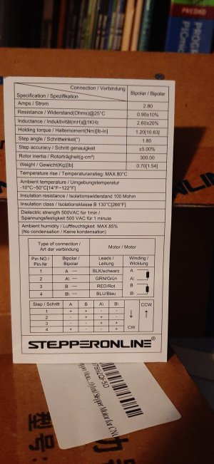
In post #3, I show the procedure I used to determine the torque required. Not too scientific but figured it was a start. As commented, the motors I had in stock were about 170 oz (actually 178 oz) motors and so I was going to be borderline. But, seeing as learning the Arduino code and trying to recall programming skills from many years ago, this whole project was an adventure/gamble, for me.

Fast forward to post #31 and the motor was pretty much exactly as expected. It would move along, then skip, idle, pulse. I could put a slight bit of pressure on the crank and it would pick up again. But at least the electronics was working out so I looked for the largest motor I could find in a NEMA23 mount and came up with this one. There was higher torque, but my controller only went to 4 amps or so, and I figured at 2.5 x the one that was borderline, it would be adequate.


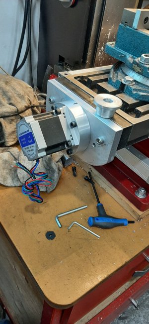
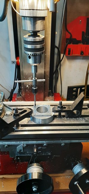
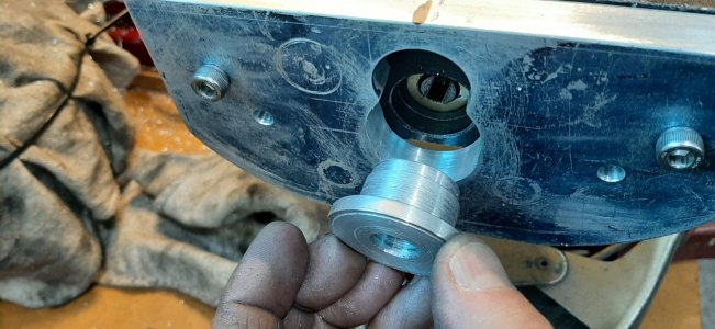
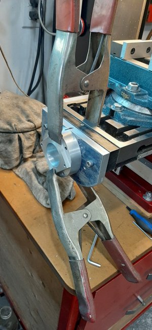
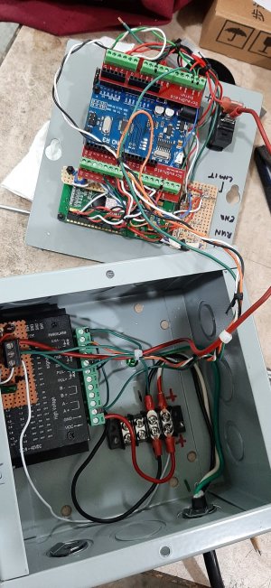
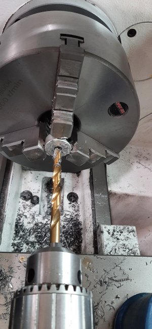
At 425 ozin, I thought it was quite a step up. As expected the mount was perfect, being a 23. I drilled out the coupling mount to accommodate the larger motor shaft size, rewired the new motor in, this time incorporating a connector instead of directly wired to the control box.

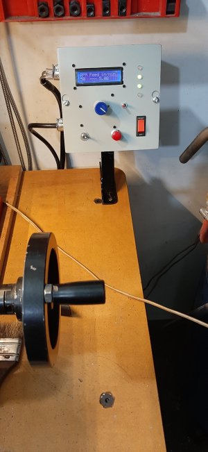
Seems to work well now. If you watch the video closely, you might pick up a slight hitch once per RPM. This is when the controller paints the display. I might rework the code to see if I can reduce the write time, but at a higher pulse rate, it should not affect the milling.

As to the feed vs RPM, my mill x lead screw is 0.100"/revolution. I just went with that. The display, due to the math, only shows even RPMs, but the feed rate is variable between. It would be an excuse to continue looking at the code to see how to display the speed with a higher resolution. In my shop, with this small mill, not necessary, but it would just be an exercise in learning. As is, it spins up to about 120 rpm, iirc. I played around with the pulses setting on the controller to find one that yielded an adequate top end, yet smooth "enough". 800 pulses/step seemed to be the magic one. The "top end" is really only used to position the table. I have never really paid much attention to feed rates before, despite reading them. I went by finish, chatter, etc. I don't think these small mills can do the feed rates/depth of cuts that engineering books suggest for the proper cut. ie, If my DOC was 0.120", as recommended yesterday for a cut, I would either break the mill or the motor would just stop. Having said that, now that I have a convenient feed display and consistent feed rate, I will be able to explore those settings more.

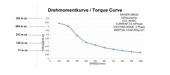
I should clarify, the motor spec sheet is the old motor and the chuck is coupling that was being modified for the new motor.

Thanks for the interest.


Attachments

  • Motor specs.jpg
    Motor specs.jpg
    313.6 KB · Views: 4
  • 20220421_100504.jpg
    20220421_100504.jpg
    360.1 KB · Views: 4
Respectfully, Civil 101 years ago taught Torque (bending moments) if you didn't get it God didn't want to become an engineer.

If you have readings this high, you have some issues in slide binding, bad bearings or lead screw/nut issues. Check this.

Secondly, steps vs servos big difference in ratings. Steps peak holding, servos at duty cycle.

YouTube Clearpath SDSK vs Stepper big difference, eye opening by NYCNC
 
Last edited:

jcdammeyer

John
Premium Member
What I was trying to say in my rather long winded explanation is that the torque curve is more important than the motor rated torque. Try and find the torque curve for that particular model motor. That will tell you how fast you should be able to run the motor before the torque falls off and you get skipping.

ShawnR: I think you meant 800 pulses per revolution?

And yes, with the servo, the rated torque, which is way lower than a stepper motor of equivalent physical size, is the important value because that torque value stays the same throughout the entire RPM range which is generally 4x that of steppers before they are inadequate.

And AC brushless servos are better than DC brushed. The DC one turned out to have a different coil resistance from the one on the X axis and tended to loose position in one direction. At first we thought it was the encoder so that was changed. Didn't make any difference. Finally just gave up and changed to the smaller size but identical RPM+Torque rating AC servo.

D8X_5544-TwoServos.jpg

With 3:1 reduction and max 3000 RPM on a 5 TPI (0.2" per rev) lead screw I get 180 ipm. Which is scary fast. And it's oh so quiet. Rated torque is 1.27 nm x 3:1 = 3.81 nm (~540 oz-in) with a peak torque of 3.9nm x 3:1 = 11.7 nm (~1650 oz-in).
D8X_5542-AC_ServoMounted.jpg

So to match that with a stepper motor requires a motor that can do 540 oz-in of torque all the way up to 750 RPM. That would be one huge stepper motor. The catch though is cost. Way more expensive with belts_pulleys+mount+servo.
 

ShawnR

Ultra Member
Premium Member
Respectfully, Civil 101 years ago taught Torque (bending moments) if you didn't get it God didn't want to become an engineer.

If you have readings this high, you have some issues in slide binding, bad bearings or lead screw/nut issues. Check this.

Secondly, steps vs servos big difference in ratings. Steps peak holding, servos at duty cycle.

YouTube Clearpath SDSK vs Stepper big difference, eye opening by NYCNC

Maybe my data, as presented, is incorrect. It does not feel hard to move at all. And, since I took those measurements, I installed the DRO. When I did that, I disassembled the table and did some deburring, cleaning, etc on the ways, so perhaps that was all a contributing factor, back when I got my data. Or my gib screws are too tight. But using the small hand crank at the end of the table, it moves ok, I think. But I will look into your recommendations.

Thanks
 

jcdammeyer

John
Premium Member
Maybe my data, as presented, is incorrect. It does not feel hard to move at all. And, since I took those measurements, I installed the DRO. When I did that, I disassembled the table and did some deburring, cleaning, etc on the ways, so perhaps that was all a contributing factor, back when I got my data. Or my gib screws are too tight. But using the small hand crank at the end of the table, it moves ok, I think. But I will look into your recommendations.

Thanks
See if you can find a torque curve for that motor.
 

ShawnR

Ultra Member
Premium Member
See if you can find a torque curve for that moto
I found this one for that model, although not the same make.
Attached is the image of the curve with calculated oz in (from an on line converter)

The way I read it, since my top speed is about 120 rpm, it should be good. (unless I am still not getting something)
Granted, I am running at 800 pulses/revolution, not 3200 and 24 vdc, not 36 so maybe the chart is irrelevant. It appears that down around 100 rpm, most motors are in the peak of their torque curve. And that is where I will be mostly


Attachments

  • Step motor torque curve.jpg
    Step motor torque curve.jpg
    77.4 KB · Views: 1

jcdammeyer

John
Premium Member
Excellent! BTW, like a DC motor, the higher the voltage the more likely you can reach higher speeds.
It has to do with how a stepper motor works which is why the torque curves are that way.

The motor winding voltage for this motor is rather high at 4.8V. The driver applies your 24V until the current reaches the max 3A per phase and then switches on/off (Chopping) holding the voltage at 4.8V and current at 3A.

The next full step requires the voltage across the winding be reversed. However, it's an inductor in a magnetic field so that takes time. By applying a higher than 4.8V value across the windings it helps change the direction of the current faster and build the new magnetic field faster so the rotor can move faster.

The second reason for the higher voltage is that like a generator, the motor when turning also generates a reverse voltage. Back EMF it's called. A simple brushed DC motor produces the same back EMF as the applied voltage and that's why the motor turns one speed at 6V and a different speed at 12V. The back EMF is the limiting factor. In simple terms.

With the stepper it's the same issue. Got to get current flowing in the windings in the opposite direction. If you can't do that fast enough before the next direction change then you never get full current through the windings. And since Torque is Amps x Turns if the Amps aren't high enough you don't get the torque. And there's the reason the for the shape of a stepper motor torque curve.
 
Top