I've been doing a ground up reconditioning on little Schaublin 70 lathe, been at it most of the year. Another case of how fast I can do it in my head not being well calibrated with my physical world performance. I've never seen a lathe in worst shape, e.g. you could grab the spindle shaft with your hand and rattle it in the bearings. However being a Schaublin, there's no more worthy candidate imo for reconditioning.
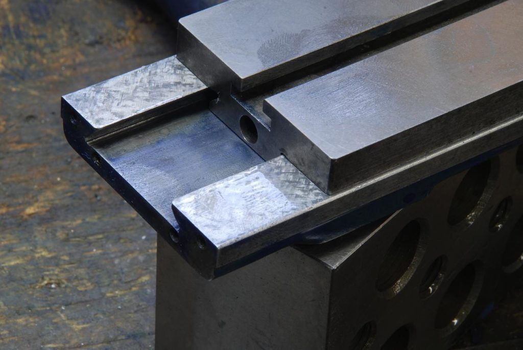
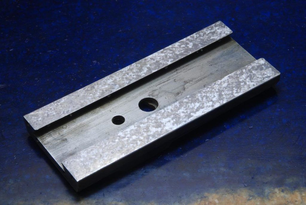
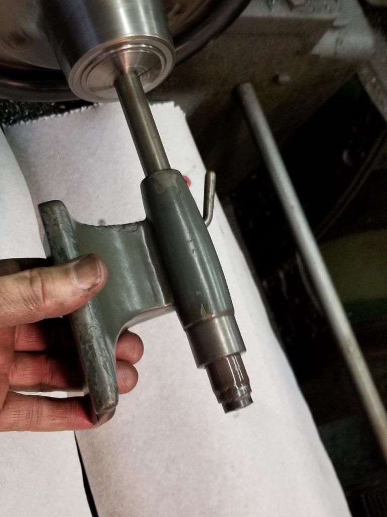
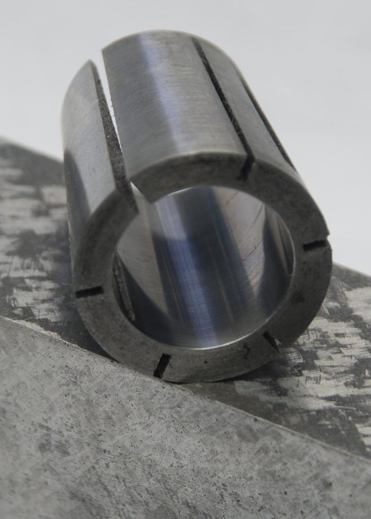
The tailstock was done by lapping the bore using home made expanding copper laps, up to 1000 grit, then hard chroming and grinding the quill to fit. There's 2 tenths clearance such that, with a bit of oil on it, if you hold the tailstock vertically, the quill won't drop out. The slide was a combination of grinding and scraping. Scraped the horizontal surfaces and ground all the angled dovetail surfaces as they are so small its about impossible to get a scraper in there, and they were short enough to set up on the surface grinder. One part of the slide assembly was so bad I grabbed a piece of cast iron and made a new one.
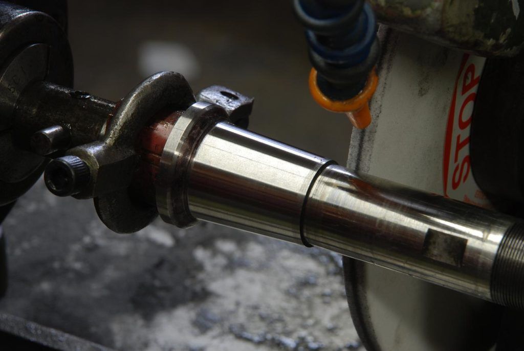
The greatest challenge was the spindle. The bearings were destroyed its the typical watchmakers format of a double 45 and 3 degrees. This to me is a near impossible machining task and I have not figured out a super elegant way to do so - the challenge being, how to machine to adjacent tapers on a shaft, then have mate with the bearing to a tenth or two clearance? Whats the diameter of taper? relative to what? You've also have the challenge that say a thou difference along the axis in where the 3 degree tapers meet, means about 10 difference in where the 45 degree tapers mate.
How I did it was grind the shaft all over, just kissing it. Then I lapped the outboard board bearing (a conical arrangement whereby tightening it's nut reduces its diameter). I then ground a shaft to fit the outboard bearing and tightened the nut until it was clamped in place. I welded up a fixture for my face plate, and then spent half day shimming and shifting until I got the said ground bar aligned in two planes each to a tenth. this should let me bore out a pressed in piece of bronze, the new headstock bearing, and have the bore aligned with the outboard bearing. The taper attached using a sine bar and careful setting was used for the 3 degree taper. I bored the 3 degree taper, and through test fitting and measuring crept up on the 45. A lot of work - and thats just the roughing!
That was the mark II attempt. The first one was a fail as I relied on the alignment of the two headstock bearing bores. Mistake, they are quit far off. Schaublin must have pressed the bearings in then bored them and did worry about the headstock cast bores very much. My lapping of the outboard side could have, and probably did, change its axis slightly, however I measure the original inboard bearing the ID and OD were substantially eccentric.
After "rouging" it was scrape and lap. The original plan was scraping, but its obviously a real challenge getting in there. I scraped until I was getting contact in most of the bearing, then lapped. While lapping tapers is verboten because there is no axial movement between the parts, I eventually discovered that the timesave stuff for use with soft metals would abrade the bronze but would not effect the steel shaft. The eventual fit came from scraping the 45 (which accessible) until there was good contact with the 3, then lapping both with the finest grade of timesavefs yellow stuff.
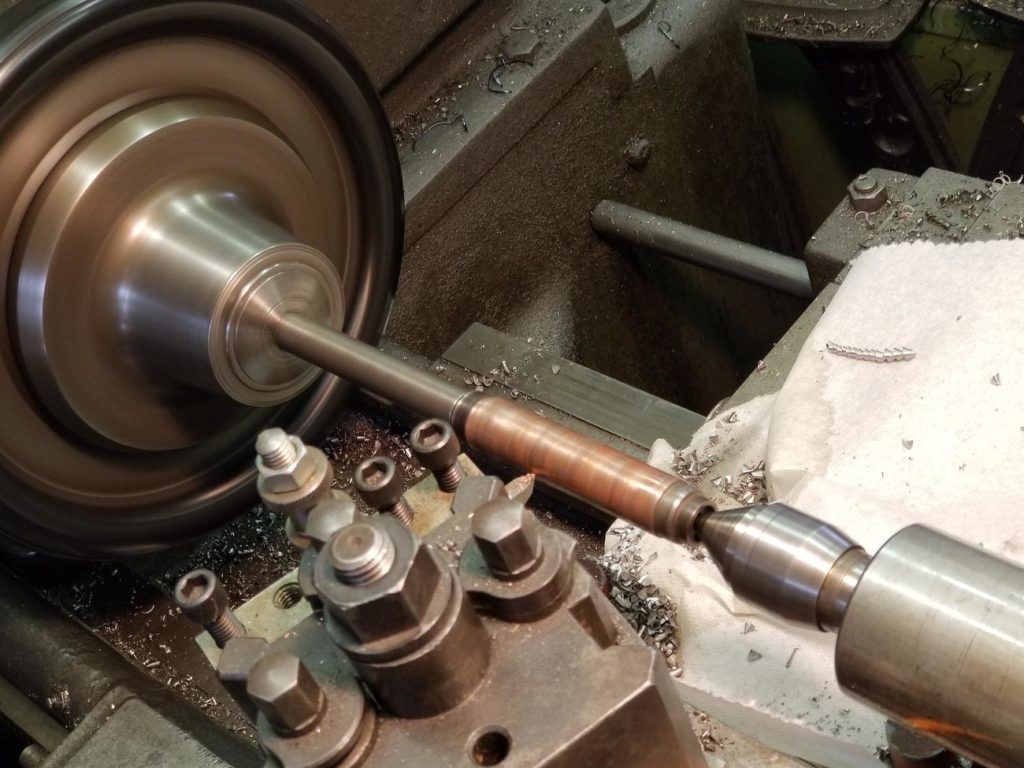
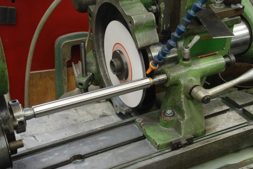
As I reground the OD of the spindle shaft, I should regrind the spindle taper to ensure concentricity. This was a big setup. Figuring it out and trying different things took me most of a day. After grinding I'm getting a tenth TIR on the spindle, was hoping for a little better, but given all surfaces on the bearings and shaft are done by me in my in the homeshop, I think its reasonably good
The headstock and tailstock after getting them fit properly, need to have their bottoms scraped to align them both to the bed and each other. That is mostly done for the headstock, tailstock still needs work
Some photos and video (I'm much better with, and really prefer still photography, but I'm learning how to bore audiences with the best of them on you tube") )
)
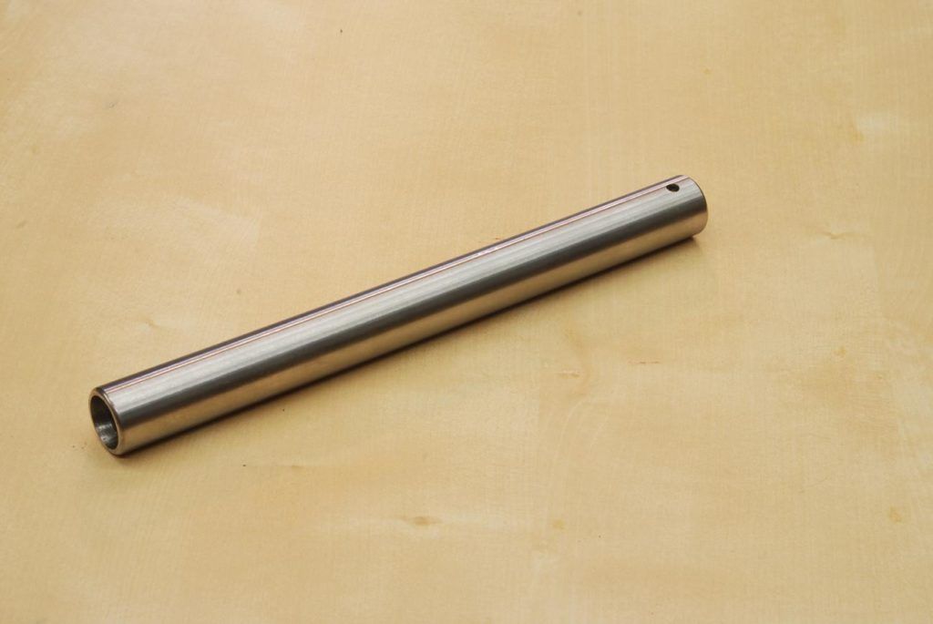
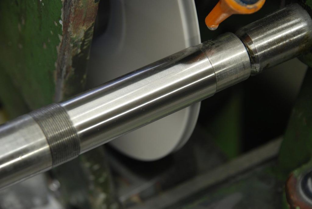
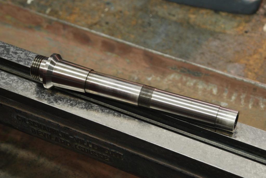
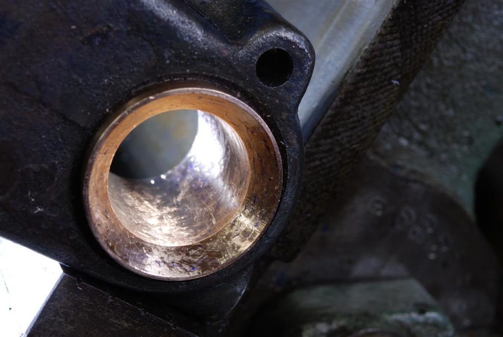
finished quill, the diameter is within about 1/2 a tenth end to end using an indicating mic
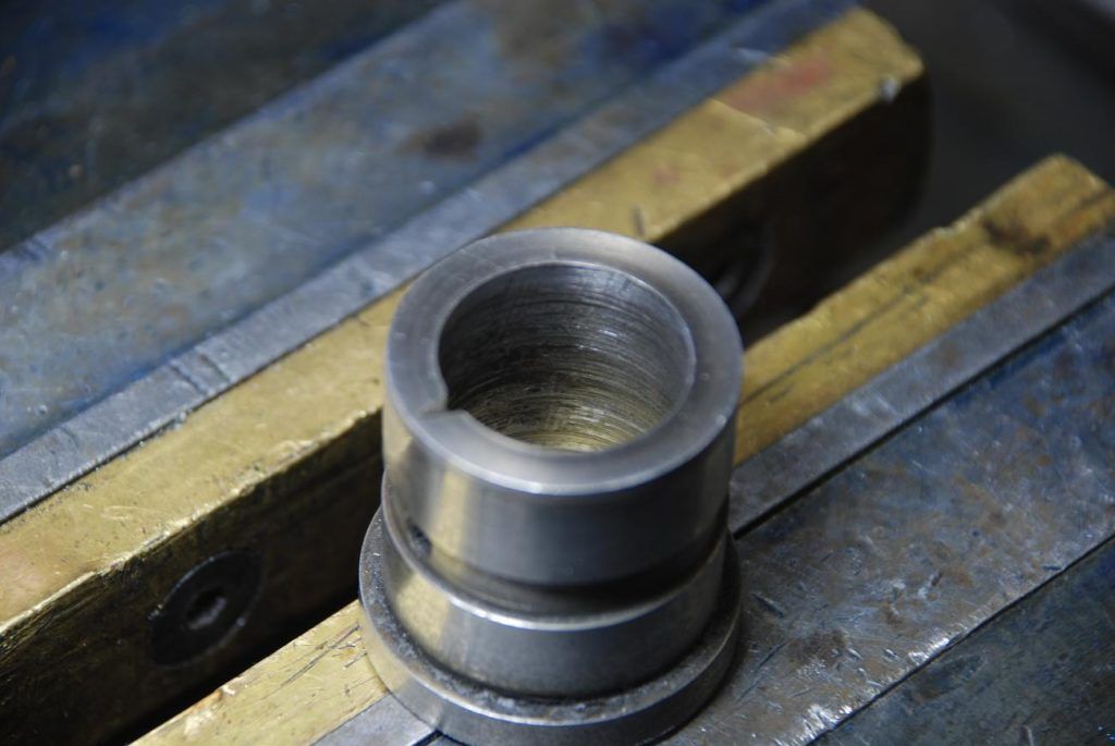
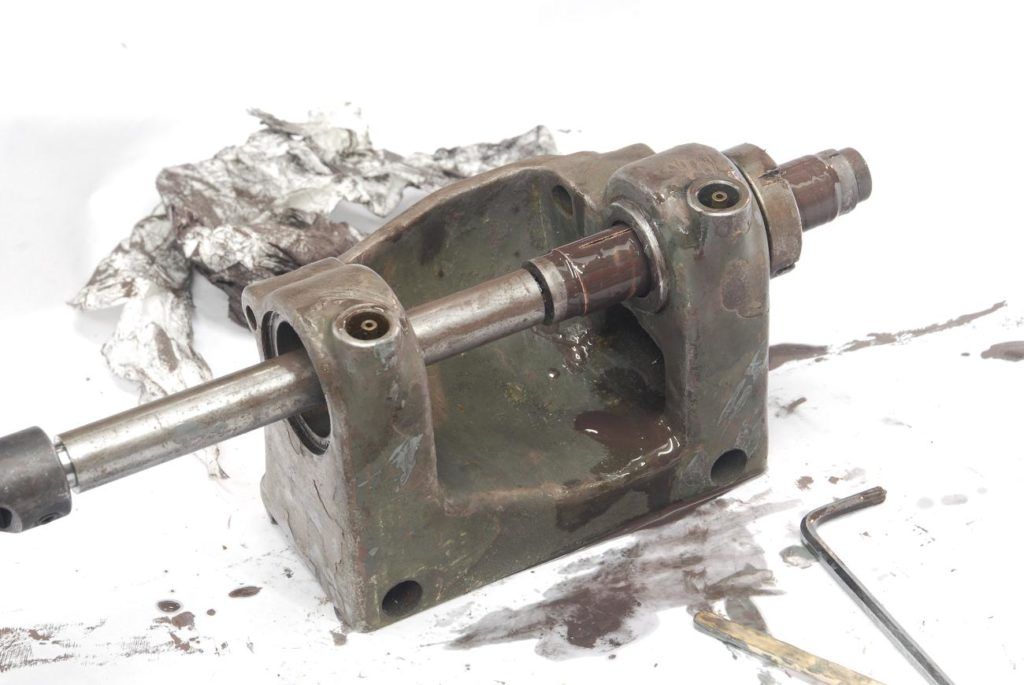
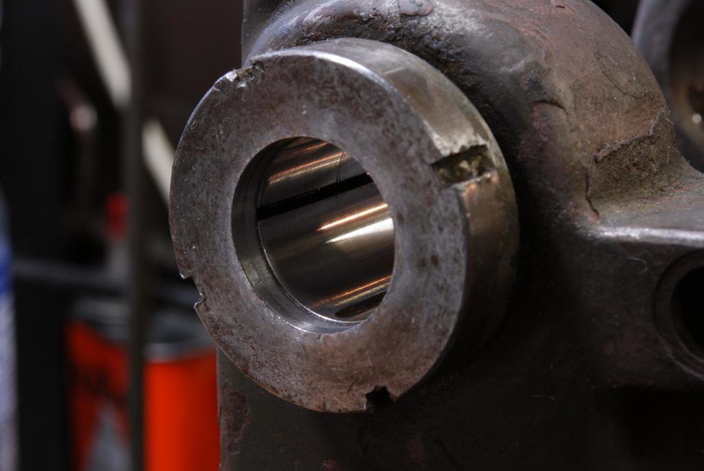
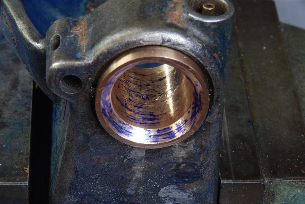
No that is pooched headstock bearing! Orginal was hardened steel. I'm going with bearing bronze (as some did Schuablin on some lathes)
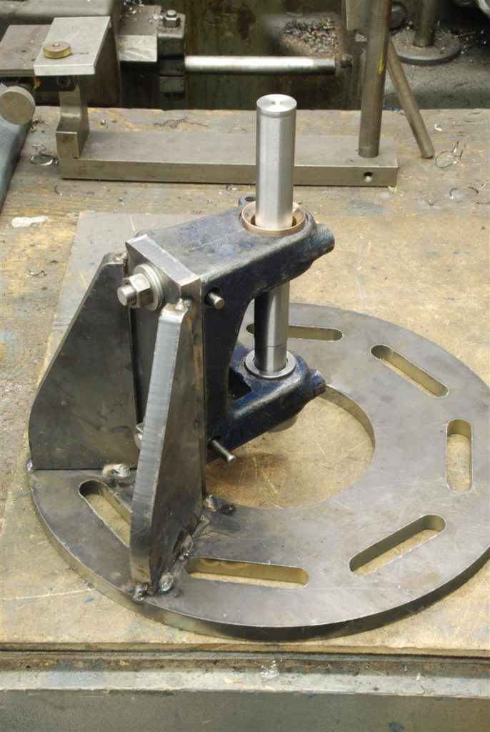
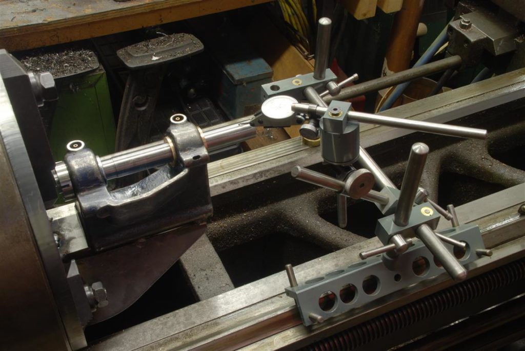
indicating the bar - its close, but not touching new bronze bearing - its bascially a perfect extension of the outboard bearing's axis
Here's a short video of turning the bronze bore....and a long video of grinding the spindle taper and the results
The tailstock was done by lapping the bore using home made expanding copper laps, up to 1000 grit, then hard chroming and grinding the quill to fit. There's 2 tenths clearance such that, with a bit of oil on it, if you hold the tailstock vertically, the quill won't drop out. The slide was a combination of grinding and scraping. Scraped the horizontal surfaces and ground all the angled dovetail surfaces as they are so small its about impossible to get a scraper in there, and they were short enough to set up on the surface grinder. One part of the slide assembly was so bad I grabbed a piece of cast iron and made a new one.
The greatest challenge was the spindle. The bearings were destroyed its the typical watchmakers format of a double 45 and 3 degrees. This to me is a near impossible machining task and I have not figured out a super elegant way to do so - the challenge being, how to machine to adjacent tapers on a shaft, then have mate with the bearing to a tenth or two clearance? Whats the diameter of taper? relative to what? You've also have the challenge that say a thou difference along the axis in where the 3 degree tapers meet, means about 10 difference in where the 45 degree tapers mate.
How I did it was grind the shaft all over, just kissing it. Then I lapped the outboard board bearing (a conical arrangement whereby tightening it's nut reduces its diameter). I then ground a shaft to fit the outboard bearing and tightened the nut until it was clamped in place. I welded up a fixture for my face plate, and then spent half day shimming and shifting until I got the said ground bar aligned in two planes each to a tenth. this should let me bore out a pressed in piece of bronze, the new headstock bearing, and have the bore aligned with the outboard bearing. The taper attached using a sine bar and careful setting was used for the 3 degree taper. I bored the 3 degree taper, and through test fitting and measuring crept up on the 45. A lot of work - and thats just the roughing!
That was the mark II attempt. The first one was a fail as I relied on the alignment of the two headstock bearing bores. Mistake, they are quit far off. Schaublin must have pressed the bearings in then bored them and did worry about the headstock cast bores very much. My lapping of the outboard side could have, and probably did, change its axis slightly, however I measure the original inboard bearing the ID and OD were substantially eccentric.
After "rouging" it was scrape and lap. The original plan was scraping, but its obviously a real challenge getting in there. I scraped until I was getting contact in most of the bearing, then lapped. While lapping tapers is verboten because there is no axial movement between the parts, I eventually discovered that the timesave stuff for use with soft metals would abrade the bronze but would not effect the steel shaft. The eventual fit came from scraping the 45 (which accessible) until there was good contact with the 3, then lapping both with the finest grade of timesavefs yellow stuff.
As I reground the OD of the spindle shaft, I should regrind the spindle taper to ensure concentricity. This was a big setup. Figuring it out and trying different things took me most of a day. After grinding I'm getting a tenth TIR on the spindle, was hoping for a little better, but given all surfaces on the bearings and shaft are done by me in my in the homeshop, I think its reasonably good
The headstock and tailstock after getting them fit properly, need to have their bottoms scraped to align them both to the bed and each other. That is mostly done for the headstock, tailstock still needs work
Some photos and video (I'm much better with, and really prefer still photography, but I'm learning how to bore audiences with the best of them on you tube
)
finished quill, the diameter is within about 1/2 a tenth end to end using an indicating mic
No that is pooched headstock bearing! Orginal was hardened steel. I'm going with bearing bronze (as some did Schuablin on some lathes)
indicating the bar - its close, but not touching new bronze bearing - its bascially a perfect extension of the outboard bearing's axis
Here's a short video of turning the bronze bore....and a long video of grinding the spindle taper and the results
Last edited:

