• Scam Alert. Members are reminded to NOT send money to buy anything. Don't buy things remote and have it shipped - go get it yourself, pay in person, and take your equipment with you. Scammers have burned people on this forum. Urgency, secrecy, excuses, selling for friend, newish members, FUD, are RED FLAGS. A video conference call is not adequate assurance. Face to face interactions are required. Please report suspicions to the forum admins. Stay Safe - anyone can get scammed.

Right Angle drive for a Bridgeport style mill.

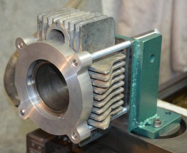
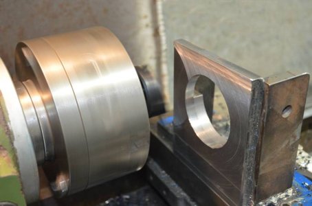
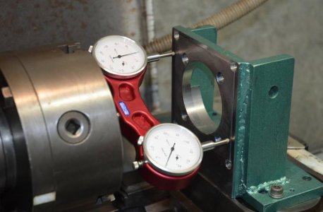
Here's a picture of what I was doing in the lathe. The slug in the 4 jaw is bored to just accept the sleeve were it protrudes from the bottom of the cylinder. The machined band on the outside is concentric so I can dial it in and I take a skim cut on the face each time I chuck it up so the cylinder registers on the base of the cylinder. I think the bore finish is good and no signs of chatter. I just don't know how much taper is OK.View attachment 28730
You are on the right track fixturing the cylinders like this . At one time I had considered using this approach .

There are lots of examples of similar arrangements when you do a search , some good , some not so good .

Then there's the debate over should I fixture the cylinder in a static position and rotate the cutting tool ? or....... fixture the cylinder in a rotating setup like you have shown and use a large boring bar . Both will work , both require attention to setup and rigidity. There's lot's of interesting ideas out there.

I've used a few different dedicated machines to bore cylinders , having done that for some time , that's my preferred way .
Before I bought my own boring bar I mulled over ways I could possibly bore cylinder with the equipment I already had .
For what I do , I decided that it was better to just tool up with the right stuff and was fortunate to find a good deal on a Van Norman 944 boring bar which will take care of pretty much every bore I might have to do.

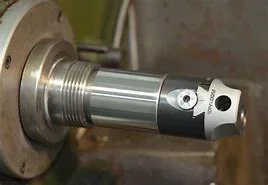
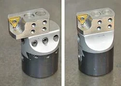
Some example of images I found .........
Boring-03.jpg
Boring-05.jpg

Boring-04.jpg

Boring head - lathe spindle mounted.jpg

Boring head attachment.JPG

This one shows a cylinder being bored to remove a damaged liner and will be re- sleeved , the existing iron liner was cast in and has ribs to lock it into the cast aluminum , the sleeve portion of the liner is pretty much gone at this point , all that remains is the ribs that were cast into the iron liner.
cylinderboringforsleve_4__3666d5f057416f411d639db5790bc4f64d22d03c.jpg
 
Last edited:
In reading some of the issues, I would suspect that if you are turning a taper on the lathe you have a head stock issue. Tool flex on ultra fin cuts (skim cuts) shouldn't give this type of deviation.

The other solution is compensate with the using the cross slide if it has the travel, even if it doesn't a little fancy work and you are golden. Once you know what the taper is, set it to compensate for flex. Old school precision is how you adjust for the limits of the machine to achieve results far beyond what the machine normally should.

Think outside the box (or cylinder in this case).
 
Last edited:
You are on the right track fixturing the cylinders like this . At one time I had considered using this approach .

There are lots of examples of similar arrangements when you do a search , some good , some not so good .

Then there's the debate over should I fixture the cylinder in a static position and rotate the cutting tool ? or....... fixture the cylinder in a rotating setup like you have shown and use a large boring bar . Both will work , both require attention to setup and rigidity. There's lot's of interesting ideas out there.

I've used a few different dedicated machines to bore cylinders , having done that for some time , that's my preferred way .
Before I bought my own boring bar I mulled over ways I could possibly bore cylinder with the equipment I already had .
For what I do , I decided that it was better to just tool up with the right stuff and was fortunate to find a good deal on a Van Norman 944 boring bar which will take care of pretty much every bore I might have to do.

Some example of images I found .........
View attachment 28791
View attachment 28792

View attachment 28793

View attachment 28794

View attachment 28795

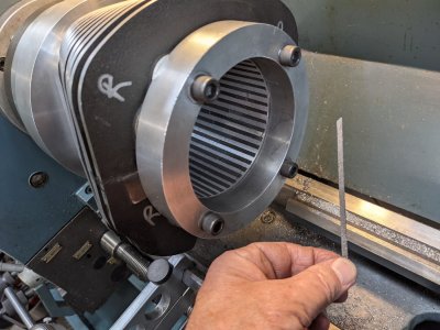
This one shows a cylinder being bored to remove a damaged liner and will be re- sleeved , the existing iron liner was cast in and has ribs to lock it into the cast aluminum , the sleeve portion of the liner is pretty much gone at this point , all that remains is the ribs that were cast into the iron liner.
View attachment 28796
I had not thought of putting the boring head in the chuck. Interesting. When I started I had no intention of boring the cylinders, What I started out to do was modernize the combustion chamber. Kawasaki triple engines were designed in the 60's when there was 100+ octane fuel. They tend not to like the current stuff. Over the years 2 stroke combustion chamber design has changed considerably. When that was done I was pretty much set up to bore the cylinder so why not. Here is the original project and tools. Heads before and after.Here are some of the tools
Head Mod Before and after.jpg


Here are some of the tools. The head is mounted on a mandrel via the spark plug hole. The disks go in the lathe tail stock to act as patterns to scribe out the inside and outside dimensions of the squish band. The spherical chamber was cut using a router radius bit in a boring bar.
PXL_20221211_231035323.jpg


This created a larger chamber and much lower compression. The cylinder was then decked to minimum squish clearance to get back the lost compression.
Chamber CC.jpg
Crank Degree wheel.jpg
Cylider Fixture.jpg
Cylinder on Lathe.jpg


Once a number of iterations getting to that stage it just seemed like the next logical step to bore the cylinders too. I'm kinda at that point were the best choice would be to have someone else do it but I don't learn anything that way. In the end I might just find some scrap cylinders and find out what I cant do.
 
There are some requirements unique to two strokes for the bore finish / sizing stage , the ports will need to be de-burred and champhered ........ and ...... the honing stones need to have double rows of abrasive to prevent them from hanging up on the ports .

What size are those bores ? , I think I can see 2.32 ..... " written with sharpie

I should say too , you appear to be getting a nice finish on the cuts you've made to the heads.
 
Last edited:
This one shows a cylinder being bored to remove a damaged liner and will be re- sleeved , the existing iron liner was cast in and has ribs to lock it into the cast aluminum , the sleeve portion of the liner is pretty much gone at this point , all that remains is the ribs that were cast into the iron liner.
View attachment 28796
You're saying you bored the original liner out completely & now this is looking at the original ribbed cylinder bore? Interesting, never heard of that before but I also don't travel in these circles.
Was the original liner hard chromed & did the insert make much fuss getting through it?
So when you insert a new liner, will it be again contacting the ribs, or the ribs will be bored away? Is that operation heat/freeze thing or press in?
 
That was a pic I discovered on a Harley tech forum , the guy doing the work is quite skilled and has a lot of out of the box ideas . What he was doing is , he had an oopsie , an expensive failure that broke the cylinder spigot below deck . A broken con rod flailed around and wrecked the crank cases too . He's got lots of parts laying around and no shortage of creativity . Some of these parts are easy to come by , some are kinda expensive , the good thing is there's lots of aftermarket support for these engines enabling an endless variety of configurations and displacements , the camshaft possibilities alone are staggering . I think he wanted to re- use the cylinders by re-sleeving them to increase the displacement . Why ? , because he can , some harley guys take their hobby very seriously , build super sized engines , then go out and beat them up . He was able to successfully bore those cylinders and install super sized liners and build an engine . The original liners were cast iron , the ribs were removed , the aluminum cylinder casting goes in the oven , the liner goes in a bucket of liquid Nitrogen when it's time to put it together . Nicasil plated bores are not that common in the harley world , other manufacturers have been using plated bores for a very long time.

You should see what happens to a top fuel Vtwin when they are having a bad day , it's devastating !!!
 
Last edited:
There are some requirements unique to two strokes for the bore finish / sizing stage , the ports will need to be de-burred and champhered ........ and ...... the honing stones need to have double rows of abrasive to prevent them from hanging up on the ports .

What size are those bores ? , I think I can see 2.32 ..... " written with sharpie

I should say too , you appear to be getting a nice finish on the cuts you've made to the heads.
60mm stock bored 2nd over to 61mm. The cylinders on the bike were bored and fitted by someone else. I just experimented on a scrap one. I have a complete spare set to play with. perhaps some more aggressive porting.
 
Talk to Don at Universal cycle , he’s a hoarder of all things Kawi H series and has been hammering them on the drag strip for years.
 
Last edited:
@Gearhead88 wouldn't a cylinder boring machine like yours do what he wants? I see these come up at auction once in a while.
It sure would. Unfortunately I have no interest in doing work for other people, so it's very hard to justify the cost and space for just my own projects and something I would use infrequently.
 
Back
Top