• Scam Alert. Members are reminded to NOT send money to buy anything. Don't buy things remote and have it shipped - go get it yourself, pay in person, and take your equipment with you. Scammers have burned people on this forum. Urgency, secrecy, excuses, selling for friend, newish members, FUD, are RED FLAGS. A video conference call is not adequate assurance. Face to face interactions are required. Please report suspicions to the forum admins. Stay Safe - anyone can get scammed.
  • The 2026 Calgary Area Meetup is set for Saturday May 30th at 10am. The signup thread is here! Robinhood has graciously offered to host the meetup again this year. Please note that you MUST RSVP to the notice linked above if you wish to come.

Reid 618HA surface grinder conversion to VFD & how to set XSY-AT1 parameters

TorontoBuilder

Sapientia et Doctrina Stabilitas
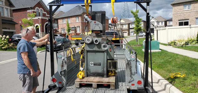
I thought I'd start a thread unrelated to the move of this machine, specifically on the power conversion.

1790218389006.jpeg


This was from a commercial auction in Windsor.

I can only assume that the shop had 575v 3 phase power.

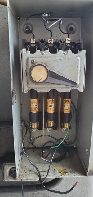
The surface grinder had a 600 volt disconnect box.
1790218470848.jpeg

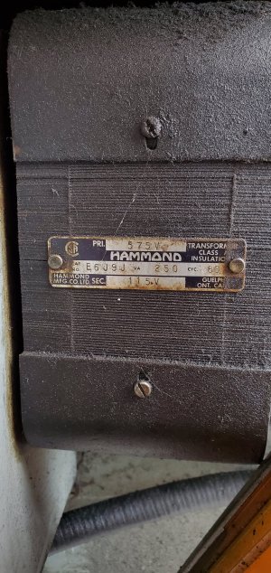
Switched power exited the left side of the disconnect box and went to a hammond transformer with 575v primary to 110 volt secondary coil outputs.
1790218666483.jpeg

The output went to a standard 2x4 electrical box. I assume that it was for a work light since the transformer is only good for ~2.17 Amps at 115 V. Maybe a very small grinding fixture motor like a Harig lectric center?

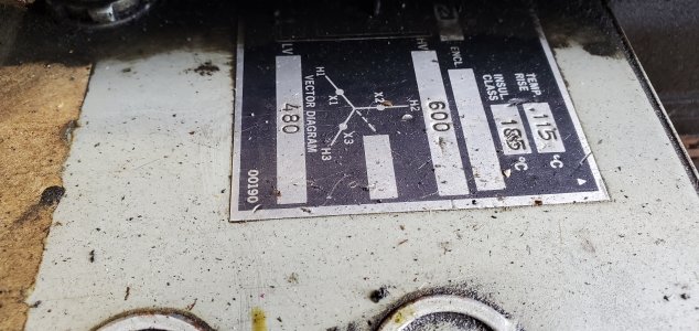
Out of the bottom of the disconnect box another set of wires went to a larger transformer to power the spindle. It's a 600v primary and 480 volt secondary.
1790220324810.jpeg

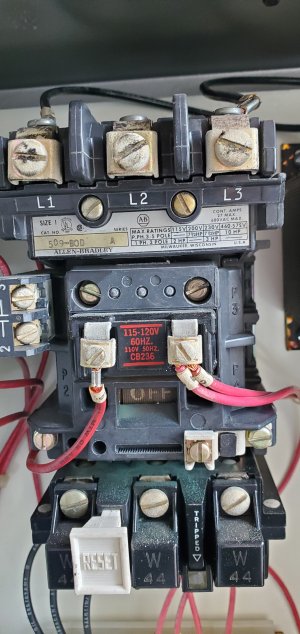
The 480v then went to a motor starter and yet another transformer. This transformer dropped the voltage from 480 to 120 volts required for the contactor's coil voltage.
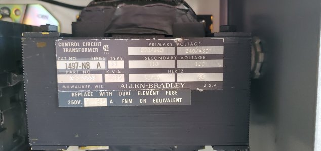
1790220372033.jpeg

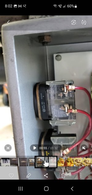
Then here is the contactor.

1790220432546.jpeg

And say goodbye to all of this.

I am plugging the machine's new power cord into a standard 240V outlet. This will pass thru a latching circuit and contactor to power up the VFD.
1790221188870.jpeg


The VFD will connect to the motor via whatever these old things are called... It is not a modern DIN rail but it is similar.
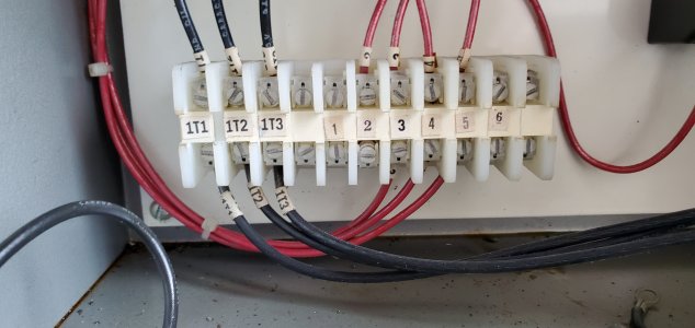

1790221149934.jpeg

This means I have wire support immediately out of the VFD terminals.
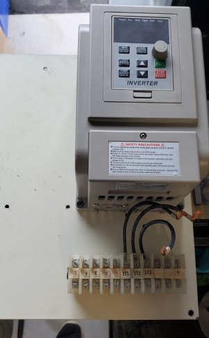
1790221259235.jpeg


This is the contactor I purchased:

Contactor, CJX2-3210 High Sensitivity Industrial Electric AC Contactor 220V 32A

The coil uses 220V so no transformers are required. The VFD has protection circuits and temperature monitoring, so no overload relay required for the contractor.

It will be vital to properly program the VFD to protect my old 1970s era motor.

Speaking of which the grinder uses a cartridge motor and spindle combination with a Whitnon dual voltage 1 HP 3ph motor.
 
The VFD will be a model XSY-AT1 from Amazon that I've had since before trump 2.0. You can get the same model now from Vevor.. but the model may be everything from the AT1-2200X to the ZW-AT1.

This thread is to retain my working notes, but should also prove beneficial to some people who wish to better understand how their VFD works and get a better set up.

As I've said previously, my Reid surface grinder uses an integral motorized cartridge spindle with 1 HP Whitnon Motor of 3400 rpm. Replacements are basically impossible to come by, so I'll be very careful not to harm this puppy. That means understanding every parameter in the VFD setup.

I chose a cheap Chinese VFD because I had one, and because the grinder is a grinder not a lathe or a mill with large low torque requirements and longer operating sessions under high loads.

I'll be running this freewheeling for warm ups and then with very light cutting loads. I will implement a soft-start to limit inrush current and an inertial stop. My reasoning will be provided later in this thread.

Here is how I will program it.


ParameterMeaningFactory DefaultMy motor requirement
P00Maximum VFD Output Voltage (volts)220220 (to match my motor)
P01Reference Base Frequency (Hz) (the motor's native frequency, changed to North American grid standard)50.060.0
P02Intermediate Voltage (This sets the mid-point voltage for a standard linear for the V/Hz scaling)110110
P03Intermediate Frequency (Hz) (This sets the mid-point frequency for a standard linear for the V/Hz scaling2530
P04Minimum Voltage (The base voltage to start V/Hz scaling, normally set at zero)0.00.0
P05Minimum Frequency (The base frequency to start V/Hz scaling, normally set at zero)0.00.0
P06Maximum Operating Frequency (The VFD's hard speed governor for calculations)6560 (3400 RPM
P07Minimum Operating Frequency (Allows full speed range down to 0)0.00.0
P10Speed Command Source (1 for Panel Potentiometer, or 0 for keys)10
P11Run / Stop Control Source (Keypad = 0 Enables the front panel RUN and STOP keys)00
P12Stopping Modes (Inertial Stop = 0, decel =1, Brake = 2, Emerg Brake = 3)10

P04, P05, P06 & P07 apply when the VFD is actively running and you change the frequency (such as turning a rheostat/potentiometer knob down to zero).

P04 is the Minimum Voltage parameter on the XSY-AT1's linear Volts-per-Hertz (V/Hz) power curve. It works in conjunction with P05.

In the standard default with P04 = 0V and P05 = 0Hz, if you use a rheostat knob to turn the speed down while the VFD is still switched "ON," you can dial it all the way down to a dead stop (0 Hz at 0 Volts).

If P04 is set to something higher, e.g., 20V and P05 is set higher, e.g., 10Hz, when you try to dial the rheostat knob all the way down, the VFD's programming will refuse to go below that floor.

It will keep the motor it spinning at a minimum baseline of 10Hz and feeding it 20V of power, no matter how low you turn the knob.

Setting a floor using P04 and P05 is an incredibly useful trick on a variable-speed lathe or milling machine.

When using an inverter-duty motor on a lathe, an operator will frequently dial the potentiometer knob down to slow the spindle for some tasks. However, if they dial it down too close to 0 Hz, the motor will stall, lose all torque, and heat up rapidly.

By setting a floor, no matter how far or fast the operator twists the speed knob, the VFD guarantees the motor never drops into a useless, high amp stalling zone.
Even if it is an inverter-duty motor rated to handle heat better, keeping a minimum RPM floor ensures the motor's fan keeps spinning fast enough to clear out heat during extended setups.

Since I am bypassing speed variations altogether and configuring my setup as a single speed 60 Hz machine, I want P04 and P05 left at exactly 0.

Leaving them at zero ensures that when I execute a Stop command, the VFD collapses its output voltage instantly and cleanly to 0V/0Hz, allowing my Whiton spindle to transition smoothly into a free coast mode for using the molybdenum stick method of truing resin bonded diamond and cbn wheels.

While P07, the minimum operating frequency, primarily dictates the lower floor when variable speed operation is desired, I've seen this set to 60 Hz where single speed motor operation is desired. This seems logical BUT doing so can create a massive conflict if you desire to implement a soft start in the later settings.
 
Last edited:
Crucial Hardware, Safety & Carrier Settings

ParameterMeaningFactory DefaultMy motor requirement
P18Grid Supply Frequency* (Tells the drive the frequency it's seeing on the utility mains)5060
P21Reduction Ratio (1 -100) OR It has a reference RPM at 50Hz depending on firmware11
P22Carrier Frequency (2-16 kHz)102, 3, or 4
P24Overload Protection Time (0.1 - 60 seconds ) How long the motor can exceed FLA setting P76.33 (seconds)
P25Motor Series Selection aka Pole Count ( 2 Pole = 0, 4 Pole =1, 6 pole = 2)00 (2 pole motor)
P26Working Frequency (0-400) (the VFD cruise control to cap user input)5060
However do you delete a row???
P34Main Rising Velocity (Acceleration Ramp Time aka soft-start) in Hz / second506
P62Display Options (Setting Frequency 0, Operating Frequency 1, RPM 2, Amps 3, Temp 4)04 (VFD Internal temp)
P76Current Coefficient (0-65535) This is the main current overload setting in mA (match motor FLA)95003000 (milliamps)

P18 is very important... it is like a tuning fork for tuning a piano.

Just like a piano tuner uses that 440 Hz fork as the absolute reference pitch to map out the mathematical intervals for all the other keys, the VFD uses P18 as its anchor pitch to scale the math behind its pulse width modulation output waveforms.

If you leave your piano tuning fork at 500 Hz but try to play a song written for 440 Hz, all the calculations are skewed and the music sounds wrong. By moving P18 from its factory default of 50 Hz to 60.0 Hz, you are successfully retuning the VFD's internal calculator so that its baseline logic lines up perfectly with a standard North American grid and motor profile. Basically, you're telling the VFD, the tone you're hearing via the utility mains is 60Hz not 50Hz.

P21 The reduction ratio is the motor to spindle pulley ratio, in this case 1 due to direct connection.
BUT on some VFDs this is the reference rpm at 50 hz. THIS MUST BE SET for the calculated actual RPM to display on the VFD screen correctly.

P22 The carrier frequency parameter selects the carrier frequency to find optimized carrier for the motor and VFD combination. A setting in the audible spectrum causes a motor hum, while too high cause voltage spikes, overheating of the IG** and transient spikes that cause pitting of the bearing races.

P22 Selects the switching frequency of the IGBTs to optimize the motor and VFD combination. A low setting in the audible spectrum (2–4 kHz) causes a noticeable motor hum but keeps the VFD cooler. Too high a setting (8–16 kHz) causes severe high voltage spikes, rapid overheating of the IGBTs, and high-frequency shaft currents that lead to bearing fluting aka pitting.
The default value of 10 corresponds to roughly 8–10 kHz to make the motor quiet. I must drop this frequency to protect the old Whiton motor insulation from high voltage spikes. I'll use the minimum of 2.

This forces the internal IGBT transistors to switch at a much lower frequency. This also keeps the VFD much cooler, which is also important since the VFD will be in a closed box to protect from grinding dust.

P24 and P34 operate in conjunction with each other to minimize the inrush current when the spindle motor is started. These two parameters ensure that the P76 parameter is never exceeded for a length of time that causes damage to the vintage motor insulation or trips the VFD into a fault. P24 allows over current for a brief 3 second period. P34 ramps up the motor speed to the full rpm over 10 second period (60hz divided by 6hz /second = 10 seconds.

Since VFD over heating may be an issue due to the installation in an enclosed electrical cabinet I am using several strategies to limit this potential and protect from accidentally causing an ERR 8 excessive temperature fault.

First, I've removed all unnecessary components and transformers from the electrical cabinet. The I selected the carrier frequency that produces the least amount of heat. Then finally I'll add a sight glass to the front of the panel that will allow me to view the VFD display occasionally.

By changing the display option parameter P62 to 4, the VFD faceplate stops showing Hz or RPM and explicitly displays the internal temperature of the VFD heatsink module in Celsius. I can then monitor, log and plot time/temperature curves to determine operating times to error code may occur and different ambient temperatures in the shop.

Then I still have another layer of protection with the VFD's auto-trip protection. The XSY-AT1 has programmable thermal protection thresholds built into its microprocessor. If the internal heat sink passes the upper limit of 80°C, the VFD will automatically sound a fault beep, stop the motor, and display an ERR 8 (Over-temperature/Module Protection) code to protect its internal circuitry from failure.
 
In the standard default with P04 = 0V and P05 = 0Hz, if you use a rheostat knob to turn the speed down while the VFD is still switched "ON," you can dial it all the way down to a dead stop (0 Hz at 0 Volts).

If P04 is set to something higher, e.g., 20V and P05 is set higher, e.g., 10Hz, when you try to dial the rheostat knob all the way down, the VFD's programming will refuse to go below that floor.
I wish to clarify on the XSY-AT1 VFD, parameters P00 through P05 are the specific parameters responsible for building and scaling the linear Volts-per-Hertz (V/Hz) power curve.

They form three pairs of XY coordinates on a graph where the horizontal axis is frequency (Hz) and the vertical axis is voltage (V).

The peak is defined by P00 (Max Voltage) and P01 (Reference Frequency).

The mid point is defined by P02 (Intermediate Voltage) and P03 (Intermediate Frequency).

The anchor point is defined by P04 (Minimum Voltage) and P05 (Minimum Frequency).


While P07, the minimum operating frequency, primarily dictates the lower floor when variable speed operation is desired, I've seen this set to 60 Hz where single speed motor operation is desired. This seems logical BUT doing so can create a massive conflict if you desire to implement a soft start in the later settings.

On the XSY-AT1 VFD, P05 and P07 both deal with minimum frequencies, but they act in two entirely separate areas of the drive's operating logic.

As mentioned above P05 dictates the shape of the electrical power curve, while P07 dictates user control limits. P05 helps define the shape of the curve... P07 allows the users to say "Okay, but I only wish to allow the motor to descend the curve to this frequency and no further.

P07 is an external user control safety limit.

It acts as a digital software guardrail that restricts the final speed command sent to the VFD's processor.

It completely ignores the power curve math and focuses purely on what the motor is allowed to do when running. It prevents the VFD from executing a continuous run command below its assigned value.

If you set P07 = 15 Hz, and you then turn an external potentiometer knob all the way down to zero, the VFD will actively intercept that signal. It basically says "This ham fisted user is asking for 0 Hz, but P07 forbids me from running lower than 15 Hz." The VFD will freeze its output and keep the motor running continuously at 15 Hz.

This is where you prevent motors from stalling by turning the potentiometer too low.
 
trlvn said:
P70, P71 and P72. I imagine you are not using these settings since you're not using variable speed. However, does your manual have a usable description of these parameters?

NOTE:

P70 thru P72 define Torque Compensation, but this VFD is less than ideal for torque compensation. If you need serious torque compensation I recommend using the vastly superior Westinghouse L510 VFD because it utilizes microprocessors capable of advanced mathematical motor modeling, sensorless vector control and intelligent dynamic calculation for torque compensation.

BUT since I know my audience and that even some lighter duty equipment can benefit from a bit of torque compensation I'll explain this to the best of my ability while admitting that I have only played around with these settings during my education process and then restored the VFD to the defaults since I had no need for compensation on the machines I have Chinese VFDs on

So...

Parameters P70, P71, and P72 are the torque compensation settings on the XSY-AT1 VFD. They are used to boost motor torque at very low speeds, aka low frequencies by artificially increasing the voltage supplied to the motor. Standard AC motors lose torque when run at low frequencies because the inherent resistance of the copper windings limits current flow. Tweaking these settings helps prevent the motor from stalling under heavy start-up loads.

Use this setting if your motor is stalling, cogging, or struggling to start moving a heavy load at low speeds (such as on a heavy bed lathe), you should adjust these values.

BUT there is also another setting that can also effect such changes. The previously mentioned V/HZ profile affected thru the P00 - P05 parameters.

It is vital to understand that modifying the V/Hz profile (P00–P05) and modifying Torque Compensation (P70–P72) are two different tools used to achieve similar goals and then decide which is the best parameter to set.

Parameters P00 through P05 define the entire permanent path of the motor's power curve from zero to maximum RPM. Shifting this line changes the core running characteristics across all frequencies.

The torque compensation parameters P70 through P72 act as a temporary low speed voltage override. They inject artificial voltage at low frequencies to overcome heavy mechanical breakaway inertia. Once the spindle is spinning and passes out of the low-frequency zone, this override tapers off, and the core V/Hz profile resumes complete control.

As a rule, modify the global V/Hz profile when the nature of the machine's load changes across its entire operating speed spectrum, e.g., how a pump or fan act vs. a spindle. The VFD defaults all assume spindle operation.

Modify the local torque boost parameters when the machine runs perfectly at normal speeds, but struggles with static breakaway inertia (start-up) or heavy loading under ~15 Hz. Basically lathes swinging large loads... or mills where you like to use face mills taking big cuts.

What each parameter means is a bitch to find out. I had to extrapolate from many sources and use manuals from westinghouse and others to see how they work to see how the knock offs are operating.

P70 simply tells the VFD which torque compensation option to use.

0 = to use value in P72,

1 = use the equation P72 x (P71 - real-time input voltage).

0 is the default.

The choice between selecting OPTION 0 or OPTION 1 for parameter P70 is VERY IMPORTANT.

P72 is a simple unitless boost gain scale from 0 to 100. This value tells the VFD to fetch a static fixed voltage value to inject from an internal look-up table, roughly ading ~5–10V to the bottom of the curve.

Crucial Warning
Do not turn P72 up too high right away. Forcing too much voltage into a slow moving motor at low frequencies causes rapid heat buildup. Because the motor's built in fan spins slowly at low speeds, a high torque boost can quickly overheat and burn out the motor windings.

Gradually increase P72.

Enter programming mode, navigate to P72, and increase it from 0 to a small number like 3, 5 or 10. Test the motor. Run your machine at a low frequency, e.g., 5 Hz to 10 Hz and see if it can handle the load without stalling. IF your motor still struggles at the selected value just select a higher number and test again... rinse, lather repeat.

BUT when you switch P70 to Option 1, and tell the VFD to use the equation P72 x (P71 - real-time input voltage) you transform the low end torque boost from a dumb, static setting into a dynamic, load-sensing voltage regulator.

The chart below compares the operational metrics of both torque compensation modes.

Operational MetricOption 0 Fixed BoostOption 1 Dynamic Slope Modifier Equation

What P71 does

Acts as a rigid voltage baseline limit.

Acts as a target crossover threshold.
Voltage Behaviour
The VFD injects the value of P72 as a flat, unyielding voltage offset.
The VFD continuously recalculates the voltage delta, tapering the boost away smoothly.
Risk
High Thermal Risk. The motor is continuously forced to run overfluxed across a wider band of low-RPM operation

Low Thermal Risk. Boost power is sharply throttled back the millisecond the motor gets through the breakaway zone.


P71 is the torque compensation voltage range of 0.0V to 300.0V. The default is typically 10V. This establishes the baseline voltage limit for the dynamic formula if P70 is set to 1.

In short, Option 0 injects a blunt block of extra voltage, while Option 1 creates a smooth, diagonal ramp down curve for the boost itself, matching the motor's actual electrical acceleration curve.

To implement dynamic boost successfully, try these starting values and logical guidelines for testing.

P70: Set to 1 to activate the dynamic equation.

P71: Set the voltage threshold ceiling to 15.0V, or leave at the factory default of 10.0V.

This tells the VFD to keep the dynamic boost active only until the core profile voltage climbs past this small window. Keeping this value low ensures the boost circuit completely shuts down before the motor speeds up and gets too hot.

P72: Set the unitless gain multiplier to 5 as a safe, baseline starting multiplier.

Step by step testing & tuning guidance:

Because P72 functions as an amplifier multiplier in the equation, you want to find the exact point where you have enough torque to start your heaviest workpiece or chuck without causing an overcurrent trip.

To test the baseline P72 = , mount your heaviest chuck, faceplate, or fixture. Attempt to start the machine at a low target frequency. e.g., 5 Hz to 10 Hz.

If the VFD instantly trips on overcurrent, ERR 1 your multiplier is too high, or your acceleration time (P34) is too fast.

Lower P72 to 3 and test again.

If the motor groans, stalls, or spins up too sluggishly, your multiplier is too low. The VFD is not injecting enough starting voltage to overcome the dead weight. Increase P72 to 8, then 12, then 15, re-testing after each change.

Once the machine starts successfully, use the FUNC / DATA key shortcut to toggle your screen over to the live Amperage (A) display. Watch the numbers. You should see a brief spike in amps right at a dead stop, which should rapidly drop down to a low, safe idling current within 2 to 3 seconds as the spindle gets up to speed.

I hope this is clear and self explanatory, but I'm happy to answer questions.
 
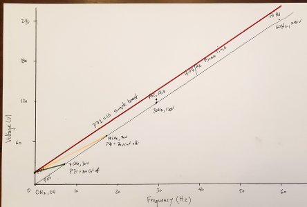
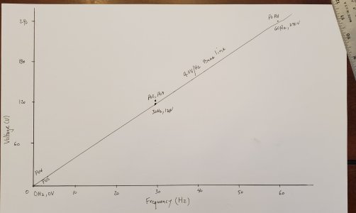
The graph below plots the exact XSY-AT1 parameters (P00 through P05) to show how the VFD builds its linear power profile for a 240v 60hz motor.

AC induction motors require a constant magnetic field, flux, to maintain torque without melting the internal windings.

The VFD handles this by dividing voltage by frequency: V/Hz ratio = 240V / 60V = 4.0V /Hz

Because this maps a perfectly straight line through the intermediate coordinates, the calculation remains identical at any given step: V/Hz ratio = 120V / 30V = 4.0V /Hz

This straight line configuration keeps the motor happy and prevents current spikes during its acceleration cycle.

1790271642702.jpeg

The Three Coordinate Points

Peak Voltage (P00, P01): Plotted at 60 Hz and 240 V.
This provides the motor with full line power at its design frequency.

Intermediate Voltage (P02, P03): Plotted at 30 Hz and 120 V.

This sits exactly at the halfway mark of the linear ramp.

Base Voltage (P04, P05): Plotted at 0 Hz and 0 V. This grounds the curve perfectly to the origin point of the graph.
 
On this economy drive, the internal logic doesn't feature dynamic curving or vector tapering.

Option 0
When you set P70 = 0 and choose a number from 1 to 100 in parameter P72, the VFD picks a fixed voltage from its internal table that matches your number.

The VFD then adds this exact same extra voltage across your entire running speed. This creates a flat, parallel lift above your original line, giving the motor a constant voltage cushion from a dead stop all the way up to full speed.
Option 0, is shown in thick red line above the standard 4.0 v/Hz baseline. This is blunt force stupid option. Just don't.

1790271888671.jpeg

Option 1 (Dynamic Fade-Out Boost)
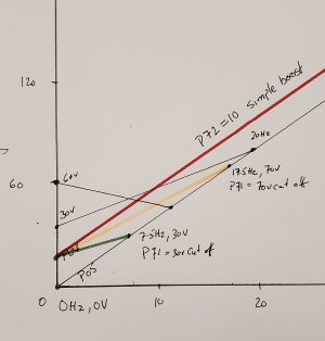
When you set P70 = 1, the VFD switches from a flat lift to an automatic calculation loop. It uses the equation mentioned previously to plot a straight diagonal line that drops down to a calculated intercept point.
By pairing your starting voltage in P72 with your fixed target voltage in P71, the VFD delivers maximum extra power at a dead stop. As the motor accelerates, the rising baseline voltage systematically shrinks the equation's output. The extra boost naturally fades out until it hits that calculated intercept point, where the boost drops to zero and merges seamlessly back into your original line.

See the Green and Yellow lines that represent two different Option 1 settings.

Inputs
Option 1 provides 2 user modifiable entries with with to influence the slope of the intercept calculation.

By having two user modifiable entries (P71 and P72), the XSY-AT1 gives you the precise dials to tune that the toque boost or "push". Think of it as trying to bump start a manual transmission car. The type of car dictates two different strategies, is it a 1970s beast needing 10 people pushing for 4 seconds, or a Lada that needs one person pushing for 10 seconds?

One dial (P72) acts like the number of people pushing, it dictates how many raw extra volts are dropped into the stator at 0 Hz to get the mass breaking free from a dead stop.

In all three examples, Red, Green and Yellow lines parameter P72 is the same. It applies the same number of people aka voltage boost to the push. This now allows us to visualize how changing parameter P71 alone influences the equation.

The other dial (P71) acts like the duration of the push, changes the calculation window to determine how high up the ramp that straight diagonal line extends before the pushers step away and let the car run on its own engine. This is because P71 acts as the baseline target voltage inside the declining calculation (P71 - Live Baseline Voltage), it directly dictates the duration of that initial push.

In this formula, P71 establishes the finish line. The larger you make the P71 number, the further the motor's live voltage has to climb before it can catch up and satisfy the subtraction down to zero.

The yellow slope reflects a higher P71 number (voltage). The live baseline voltage has a long way to climb before it can match the target. This keeps the subtraction term active over a wider frequency range, extending the boost further up the ramp (longer duration).


The green slope reflects a lower P71 number (voltage). The live baseline voltage catches up to the target quickly at a much lower frequency. The subtraction term collapses to zero early, terminating the boost closer to startup (shorter duration).

To tune this equation you can use your ears. They can tell you if you need more people pushing, if the push duration is too short or too long. I used the same P72 parameter to compare equations, but in real life you can and should vary both parameters.

In the graph below I added two more examples, with more people pushing, e.g. two higher P72 values ... and different P71 parameters as well.
1790280276792.jpeg
 
So @Susquatch this should interest you since this is the same VFD I installed on your KO Lee surface grinder.

I admit that I only entered the barest parameters at the time to get the grinder spindle working.

IF I recall correctly, they wheels I tried didn't require any effort to get spinning so no torque compensation was needed, and I didn't program a soft start either or a deceleration.

You may want both of those. I've decided to have a deceleration because I am absent minded and may forget the inertial stop lets the wheel spin down over a long period. I'd grind the back of my hand. Just like by buddy Dave cut his hand on the chop saw.

I'll reserve the inertial stop to temporary use when I want to true all my diamond and cbn wheels at one session.

I do have on experiment I want to run when I buy another westinghouse VFD. I want to do test grind comparisons.

The economy VFD versus premium. Identical set-ups with one exception... the Westinghouse has slip compensation to maintain constant velocity under load. This is theory should yield a finer finish when all else is equal.

Then I'd do a third case... the absolute tricked out westinghouse settings with vectorless sensor operation, slip compensation, every parameter I can tweak to see it the finish improves.
 
I misremembered.

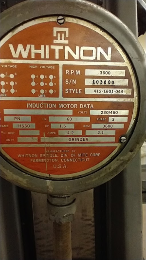
The motor is 1.5 HP not 1.

Therefore the amps is not 3. I need to revise my P76 parameter from 3000 mA to 4200 mA.

I also need to open up this plate and change to a low voltage connection

1790293274761.png
 
Then I'd do a third case... the absolute tricked out westinghouse settings with vectorless sensor operation, slip compensation, every parameter I can tweak to see it the finish improves.

It should. The difference in smoothness between SLV mode and regular mode on the Westinghouse Teco borders on incredulous. It has to be seen, heard, and felt in person to believe. Nothing I could tell you would prepare you for the experience. It's like your motor just got a rotor balance and 10 thousand dollar bearings.

But it isn't painless. At least not on the Teco. The required settings are not intuitive and often blow up in your face with a motor that won't start or growls like a banshee. Once you get it working, you are afraid of changing it. Is it worth the premium and the hassle? HELL YES!
 
It should. The difference in smoothness between SLV mode and regular mode on the Westinghouse Teco borders on incredulous. It has to be seen, heard, and felt in person to believe. Nothing I could tell you would prepare you for the experience. It's like your motor just got a rotor balance and 10 thousand dollar bearings.

But it isn't painless. At least not on the Teco. The required settings are not intuitive and often blow up in your face with a motor that won't start or growls like a banshee. Once you get it working, you are afraid of changing it. Is it worth the premium and the hassle? HELL YES!
well shit.... do I need to save this VFD for the knife grinder and buy a new Teco L510?

I wish they'd give me a discount on two, because I need to purchase one for my lathe soon...
 
well shit.... do I need to save this VFD for the knife grinder and buy a new Teco L510?

I wish they'd give me a discount on two, because I need to purchase one for my lathe soon...

Try it first. Who knows. It may perform just as well.

But I confess that I have 3 Tecos for that reason. I got them from E-Motors and I did get a discount. But they were still big bucks.

I'm envious of your work with the Chinese VFD. I did precious little of that kind of work. Most of my scope work was done chasing after input line noise and output EMR suppression.
 
Try it first. Who knows. It may perform just as well.

But I confess that I have 3 Tecos for that reason. I got them from E-Motors and I did get a discount. But they were still big bucks.

I'm envious of your work with the Chinese VFD. I did precious little of that kind of work. Most of my scope work was done chasing after input line noise and output EMR suppression.
Yeah I went whole hog on noise suppression on the lathe conversion. I need not have bothered
 
John, Is torque compensation something that most VFD's have? I'm looking through the programing manual for 2 of my 3 VFDs and I can't find anything labeled P70, P71, P72, could they have a different designation?
As far as I know almost all budget VFDs mass manufactured out of China include torque compensation hardware capabilities.

However, their manuals are notoriously shitty, undocumented, or use entirely bonkers technical terms. Because many Chinese factories share or clone baseline logic boards, these features are hidden under a few common, unlabelled parameters.

In order to narrow it down, you need to look at the original manual and see what model it most closely relates to and then look for a better manual... OR look at the name the call their parameter settings to determine the manufacturer... of a manufacturer's model numer.

Get me the labels for their first dozen inputs and I can try to point you in the right direction. I've been reading thru many of the variant models manuals over the past two weeks.
 
Back
Top