TorontoBuilder
Sapientia et Doctrina Stabilitas
I thought I'd start a thread unrelated to the move of this machine, specifically on the power conversion.
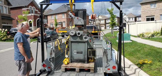
This was from a commercial auction in Windsor.
I can only assume that the shop had 575v 3 phase power.
The surface grinder had a 600 volt disconnect box.
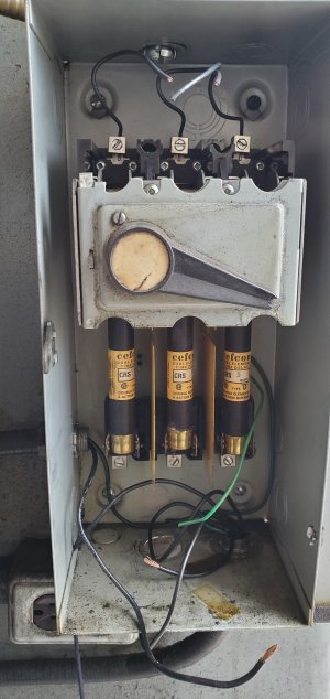
Switched power exited the left side of the disconnect box and went to a hammond transformer with 575v primary to 110 volt secondary coil outputs.
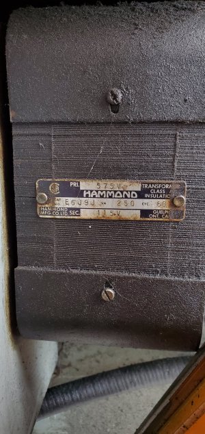
The output went to a standard 2x4 electrical box. I assume that it was for a work light since the transformer is only good for ~2.17 Amps at 115 V. Maybe a very small grinding fixture motor like a Harig lectric center?
Out of the bottom of the disconnect box another set of wires went to a larger transformer to power the spindle. It's a 600v primary and 480 volt secondary.
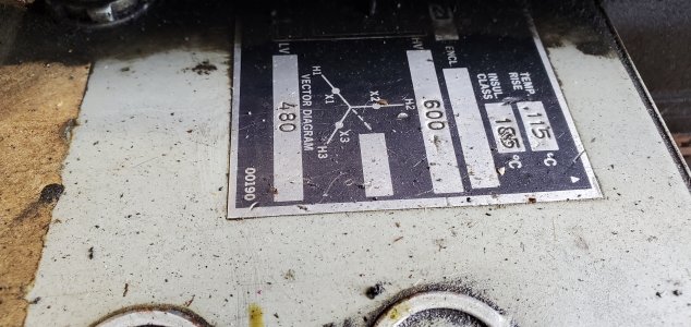
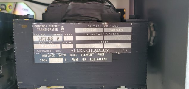
The 480v then went to a motor starter and yet another transformer. This transformer dropped the voltage from 480 to 120 volts required for the contactor's coil voltage.
Then here is the contactor.
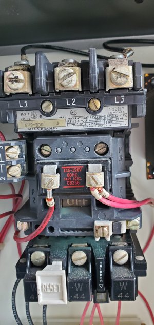
And say goodbye to all of this.
I am plugging the machine's new power cord into a standard 240V outlet. This will pass thru a latching circuit and contactor to power up the VFD.
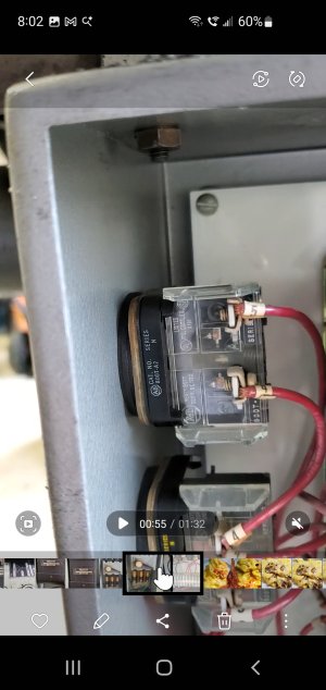
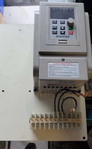
The VFD will connect to the motor via whatever these old things are called... It is not a modern DIN rail but it is similar.
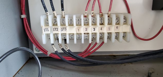
This means I have wire support immediately out of the VFD terminals.
This is the contactor I purchased:
Contactor, CJX2-3210 High Sensitivity Industrial Electric AC Contactor 220V 32A
The coil uses 220V so no transformers are required. The VFD has protection circuits and temperature monitoring, so no overload relay required for the contractor.
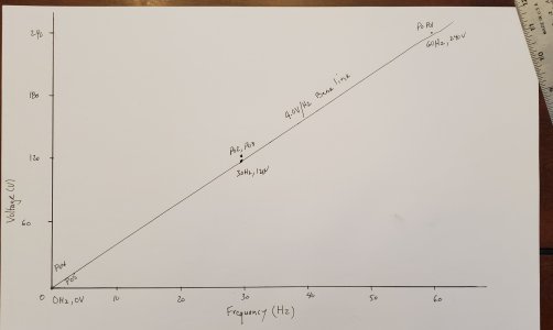
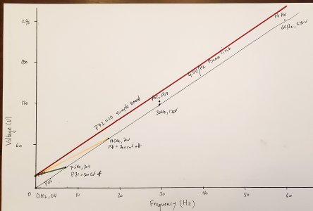
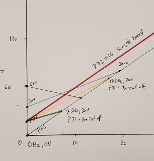
It will be vital to properly program the VFD to protect my old 1970s era motor.
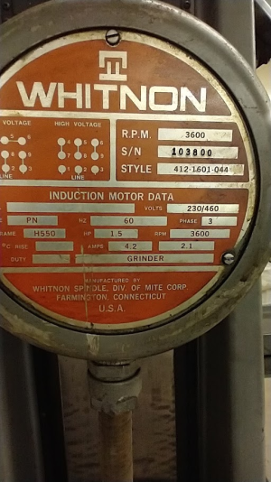
Speaking of which the grinder uses a cartridge motor and spindle combination with a Whitnon dual voltage 1 HP 3ph motor.
This was from a commercial auction in Windsor.
I can only assume that the shop had 575v 3 phase power.
The surface grinder had a 600 volt disconnect box.
Switched power exited the left side of the disconnect box and went to a hammond transformer with 575v primary to 110 volt secondary coil outputs.
The output went to a standard 2x4 electrical box. I assume that it was for a work light since the transformer is only good for ~2.17 Amps at 115 V. Maybe a very small grinding fixture motor like a Harig lectric center?
Out of the bottom of the disconnect box another set of wires went to a larger transformer to power the spindle. It's a 600v primary and 480 volt secondary.
The 480v then went to a motor starter and yet another transformer. This transformer dropped the voltage from 480 to 120 volts required for the contactor's coil voltage.
Then here is the contactor.
And say goodbye to all of this.
I am plugging the machine's new power cord into a standard 240V outlet. This will pass thru a latching circuit and contactor to power up the VFD.
The VFD will connect to the motor via whatever these old things are called... It is not a modern DIN rail but it is similar.
This means I have wire support immediately out of the VFD terminals.
This is the contactor I purchased:
Contactor, CJX2-3210 High Sensitivity Industrial Electric AC Contactor 220V 32A
The coil uses 220V so no transformers are required. The VFD has protection circuits and temperature monitoring, so no overload relay required for the contractor.
It will be vital to properly program the VFD to protect my old 1970s era motor.
Speaking of which the grinder uses a cartridge motor and spindle combination with a Whitnon dual voltage 1 HP 3ph motor.