• Spring 2024 meetup in Calgary - tentative date Saturday, April 20/2024. Other regions are also discussing meet ups. If you want one in your area get going on organizing it! discussion
  • We are having email/registration problems again. Diagnosis is underway. New users sorry if you are having trouble getting registered. We are exploring different options to get registered. Contact the forum via another member or on facebook if you're stuck. Update -> we think it is fixed. Let us know if not.
  • Spring meet up in Ontario, April 6/2024. NEW LOCATION See Post #31 Discussion NEW LOCATION

Radial engine build

PeterT

Ultra Member
Premium Member
Hi Jon. The plans were purchased here, Martin Ohrdorf. http://www.engineman.de/
Bit of background story. I originally bought the 9-cyl plans a few years back, but it was for design reference when I was naively contemplating my own 5-cyl radial design. Then one day I noticed he subsequently offered a 5-cyl version that shares certain 9-cyl components. So I ended up getting the 5-cyl plans figuring the smaller brother would be a big enough challenge for me. Unfortunately he makes you buy both sets (or at least he did at the time) which is a bit goofy since they are 2D drawings of 3D Cad assembly which could be offered as standalone IMO. But since I already had the 9 plans, I took the leap. He also offers a V12 & a double row 7 (14 cyl corncob) which look to be similar design methodology. There are some Youtubes of his engines running. Correspondence is spotty at best (maybe language issue).

I’ll mention some other options because this absorbed a lot of my decision making time.

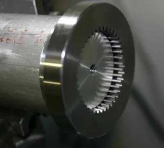
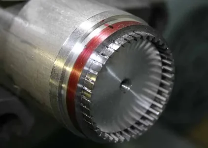
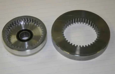
Free (legitimate free) PDF plans are available for the Edwards engine 5-cyl radial which is quite similar. I have a copy if you are interested (version A08a), otherwise I think you just need to join Yahoo R&R user group to access. There are some pros & cons & slight aesthetic differences. Edwards has integrated mechanical lubrication pump so it runs pure methanol as fuel & circulates oil where required. This would be my preference over the typical premix oil/methanol RC fuel, but they seem to run ok & the commercial engines are premix too. The Edwards has some documented builds on some forums, not the case with Ohrdorf. I was prepared to start the Edwards but found difficulty sourcing the internal (IMP) tooth ring gear. That’s the one critical thing you need to nail down beforehand on these radials. External spur gears can be made by hobby machinists but internal ring tooth form, especially at this scale & ideally hardened, not so easy. Unfortunately it’s the heart of the engine design because of physical size & requisite gear ratio combination for cam lobe timing etc. The euro engines use same crankshaft > idler > ring gear > lobe cam principal but use module (metric) gears. I was able to locate the metric one so that sealed the deal. Since then I’ve stumbled on the required Edwards ring gear, but too late now.

Here is another supplier which look to be pretty good designs. They also offer some simpler & lower cylinder count engines - probably what I should have pursued first, but oh well. They are also methanol fuel / glow ignition, all metric. And also a 5-cyl radial btw.
http://www.cad-jung-shop.de/epages/62479729.sf/de_DE/?ObjectPath=/Shops/62479729/Categories/Baupl%C3%A4ne/Bauplane_Modellmotore

This link shows some build pics of the 7-cyl radial.
http://philsradial.blogspot.ca/
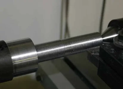
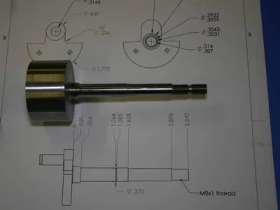
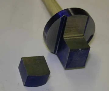
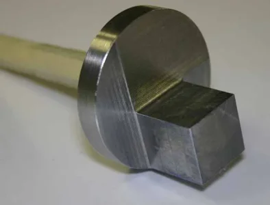
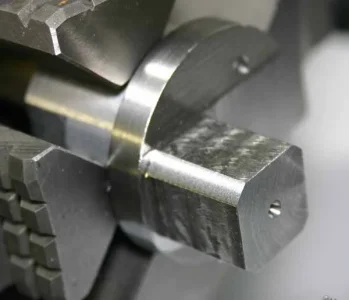
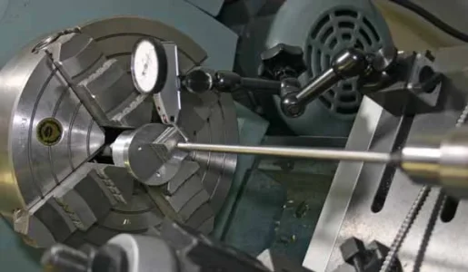
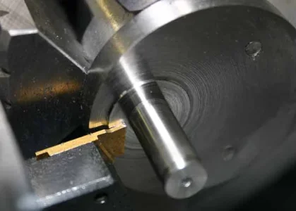
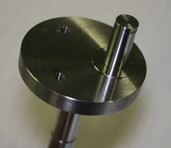
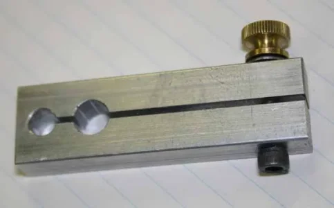
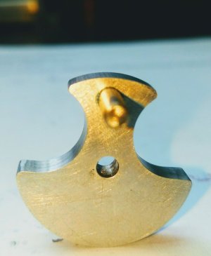
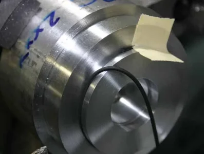
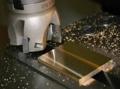
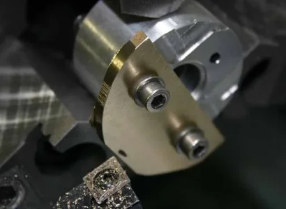
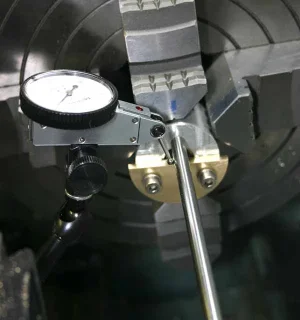
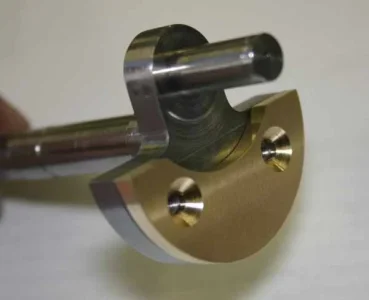
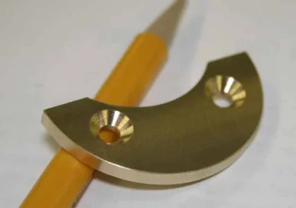
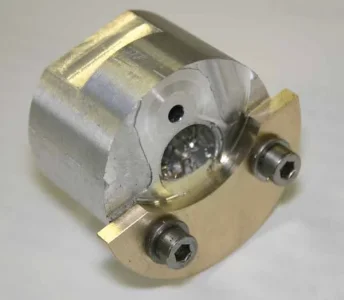
 

PeterT

Ultra Member
Premium Member
Well it was almost a year ago, roughing out this very same lump of steel that my lathe power feed decided to cough a fur ball. Long saga but its all better now. So finally time to get after the crankshaft for this radial engine again. It was a very fussy bit of machining - several bearing surfaces to pretty tight tolerances, retaining ring grooves, bearing bosses, eccentric crankpin machined from solid, nice fit to master rod bronze bushing, web cut outs.... Its made from solid 1144 stress proof steel. First time I've used this but I like the material. Its quite tough but finishes well & does most important does not banana with all the metal removed which is key.

I almost botched one of the critical bearing surfaces. After lapping down to OD where bearings were a nice reasonably tight but position-able fit, I quit for the night. Next day the bearing slid on with alarming easiness. Not rocking buy way looser than it was the day before. I re-miked & sure enough was 0.0003" under what I wrote down the day before. WTF? Apparently I still had resident heat in the bar, enough that it was still under thermal expansion even while working the last couple thou & lapping for probably an hour after turning. I just assumed it had returned to close enough to room temp. Lesson learned, disaster avoided. Actually the front gearbox assembly requires retaining compound so worked out in the end. Well this was my first crankshaft, glad it turned & behind me. Now I can proceed to the next parts in line - planetary gear assembly, cams etc.
 

Attachments

  • IMG_5841_edited-1.jpg
    IMG_5841_edited-1.jpg
    29.3 KB · Views: 12
  • IMG_6609_edited-1.jpg
    IMG_6609_edited-1.jpg
    32.1 KB · Views: 12
  • IMG_6634_edited-1.jpg
    IMG_6634_edited-1.jpg
    30.5 KB · Views: 12
  • IMG_6631_edited-1.jpg
    IMG_6631_edited-1.jpg
    30.1 KB · Views: 12

PeterT

Ultra Member
Premium Member
Crankpin stuff
 

Attachments

  • IMG_6647_edited-1.jpg
    IMG_6647_edited-1.jpg
    26.7 KB · Views: 15
  • IMG_6650_edited-1.jpg
    IMG_6650_edited-1.jpg
    43 KB · Views: 15
  • IMG_6652_edited-1.jpg
    IMG_6652_edited-1.jpg
    38.9 KB · Views: 15
  • IMG_6657_edited-1.jpg
    IMG_6657_edited-1.jpg
    26.3 KB · Views: 15
  • IMG_6660_edited-1.jpg
    IMG_6660_edited-1.jpg
    37 KB · Views: 15
  • IMG_6661_edited-1.jpg
    IMG_6661_edited-1.jpg
    30.8 KB · Views: 14
  • IMG_6667_edited-1.jpg
    IMG_6667_edited-1.jpg
    33.4 KB · Views: 15

PeterT

Ultra Member
Premium Member
Web removal & finishing.
An additional counterweight segment gets bolted to the two M3 thread holes.
 

Attachments

  • IMG_6671_edited-1.jpg
    IMG_6671_edited-1.jpg
    42.8 KB · Views: 15
  • IMG_6676_edited-1.jpg
    IMG_6676_edited-1.jpg
    43.3 KB · Views: 15
  • IMG_6677_edited-1.jpg
    IMG_6677_edited-1.jpg
    46.6 KB · Views: 15
  • IMG_6682_edited-1.jpg
    IMG_6682_edited-1.jpg
    32 KB · Views: 16
  • IMG_6683_edited-1.jpg
    IMG_6683_edited-1.jpg
    25.3 KB · Views: 16
  • IMG_6686_edited-1.jpg
    IMG_6686_edited-1.jpg
    29.7 KB · Views: 16

DPittman

Ultra Member
Premium Member
Ok for a good laugh.....here's an example of the greatly different skill levels on this forum....you've seen Peters' amazing skills on that crank.....now for something completely different....
Here's a picture of my first ever attempt at a little crank I made just today on my lathe and home made milling attachment. Overall dimension is 1".

Humbling but inspiring to see such knowhow as yours Peter!

Don
 

Attachments

  • IMG_20180217_1529082.jpg
    IMG_20180217_1529082.jpg
    78.2 KB · Views: 14

DPittman

Ultra Member
Premium Member
Well, no particular engine yet, I'm just trying out some component making. I want to make some very small steam/air wobbler engines. Here's a shot of some very tiny machining I also did in making a steam shut off valve for a not yet made boiler.
I have no clue how to make a boiler either so any advice is always welcome . IMG_20180217_1916573~01.jpg
 

PeterT

Ultra Member
Premium Member
Another finicky part (half done). This is the gear plate. The small boss OD slide fits into the crankcase within 0.0005" & has bearing recess. The bigger boss OD will slide fit the nose case to same tolerance. It still needs some fastener holes, counter bore & shaft hole for idler gear. The business end of the planetary gear cluster & lobe cams reference off this & crankshaft geometry.

What caught me off guard was the drawing shows 1.5mm width groove for 1.5mm nominal O-ring section which I followed. These seal the nose case oil bath from entering the CC, but you also have to get the parts on & off. In hindsight I should have realized the same 1.5mm groove/O-ring nominal width cant work (and they didn't). No way I could push the CC on test fitting on the lathe. The gap needs to be wider to allow O-ring squish room to oval out. This is 70 durometer Viton cord. In retrospect I should have made a test coupon beforehand to pre-establish the fit vs winging it on the real part.

Turns out many variables affect gap width apparently: the durometer, groove ID, tolerance of O-ring section & nominal diameter, what kind of seal is required (degree of interference fit). Anyway I was already committed to the groove depth so basically crept up on the width until I got the right fit. This engine design is German, very few instructions. I figure either he used some super soft silicone O-rings or just left the drawing as guideline starting point. And on we go!
 

Attachments

  • IMG_6700_edited-1.jpg
    IMG_6700_edited-1.jpg
    38.5 KB · Views: 17
  • IMG_6713_edited-1.jpg
    IMG_6713_edited-1.jpg
    29.4 KB · Views: 17
  • IMG_6714_edited-1.jpg
    IMG_6714_edited-1.jpg
    42.6 KB · Views: 17
  • IMG_6716_edited-1.jpg
    IMG_6716_edited-1.jpg
    30.1 KB · Views: 16
  • IMG_6717_edited-1.jpg
    IMG_6717_edited-1.jpg
    46.6 KB · Views: 16
Last edited:

RobinHood

Ultra Member
Premium Member
Super cool PeterT! Beautiful work.

I remember reading up on that build on a German forum quite some time ago. Just can’t recall which one....
 

PeterT

Ultra Member
Premium Member
Brass counterweight addition for crankshaft. One of those 5 minute jobs that took 3 hours :) It has a relief arc cut to accommodate the master rod, but its center occurs at a different center than the OD, so required 2nd setup in the 4 jaw. I integrated that registration point in the same fixture used to hold the crankshaft for crank pin turning. Sometime one spends the same time on fixtures as the part. Brass face mills really nice with the sharp uncoated inserts used on aluminum.
 

Attachments

  • IMG_6719_edited-1.jpg
    IMG_6719_edited-1.jpg
    44.8 KB · Views: 17
  • IMG_6723_edited-1.jpg
    IMG_6723_edited-1.jpg
    35.3 KB · Views: 19
  • IMG_6727_edited-1.jpg
    IMG_6727_edited-1.jpg
    44.6 KB · Views: 20
  • IMG_6732_edited-1.jpg
    IMG_6732_edited-1.jpg
    29.5 KB · Views: 19
  • IMG_6731_edited-1.jpg
    IMG_6731_edited-1.jpg
    26.8 KB · Views: 19
  • IMG_6730_edited-1.jpg
    IMG_6730_edited-1.jpg
    34.9 KB · Views: 19

PeterT

Ultra Member
Premium Member
Sh*ts getting real now! ha-ha. After making a few more drive line parts, I spent the day getting my brain around the planetary gear assembly. The gears are modified from steel commercial Mod-1 (metric) gears, so will require special fixtures to hold them. But I think I'm going to make some (OD/ID/pitch diameter) mock-up gear blanks because there are so many inter-related fits above & beyond them just meshing.

The short story is the crankshaft has a 15-tooth gear attached. It drives an idler cluster 15-tooth / 10-tooth & the 10 drives the 40 tooth internal (ring) gear... which gives the 4:1 ratio & drives the intake/exhaust cams.
 

Attachments

  • IMG_6758_edited-1.jpg
    IMG_6758_edited-1.jpg
    35.4 KB · Views: 19
  • IMG_6759_edited-1.jpg
    IMG_6759_edited-1.jpg
    30.3 KB · Views: 20
  • IMG_6762_edited-1.jpg
    IMG_6762_edited-1.jpg
    30.3 KB · Views: 20

PeterT

Ultra Member
Premium Member
Turning a commercially purchased 40-tooth Mod-1 internal gear. This is part of the planetary gear drive train that drives the 2 lobed cams at 4:1. Ring gears, or more specifically ring gear internal tooth profiles are very difficult to make accurately in home shop environment. In fact I was just real happy to get this to size without botching it, because they are not exactly easy to source. It had to be reduced in both diameter and in thickness to fit an aluminum bearing cup, which I made beforehand.

The trick is to maintain accurate concentricity on the teeth & also not allow the gear to move under 2 different machining steps. So I turned a very snug fitting shoulder spigot in the lathe insitu, then without removing it from chuck, applied my CA-glue treatment, positioned the gear & clamped with a plate. This steel is tough stuff so light cuts & patience. Luckily it held during the facing job too. If I did this again I would make provisions for a brass pin to rest against a gear acting kind of like an internal dog. But I also didn't want to have too many things glued in place because they can be a bugger removing even with butane torch heat.
 

Attachments

  • IMG_6829_edited-1.jpg
    IMG_6829_edited-1.jpg
    33.8 KB · Views: 21
  • IMG_6831_edited-1.jpg
    IMG_6831_edited-1.jpg
    36 KB · Views: 22
  • IMG_6836_edited-1.jpg
    IMG_6836_edited-1.jpg
    70.9 KB · Views: 24
  • IMG_6844_edited-1.jpg
    IMG_6844_edited-1.jpg
    37.9 KB · Views: 25
  • IMG_6853_edited-1.jpg
    IMG_6853_edited-1.jpg
    32.4 KB · Views: 24
Top