• Spring 2024 meetup in Calgary - tentative date Saturday, April 20/2024. Other regions are also discussing meet ups. If you want one in your area get going on organizing it! discussion
  • We are having email/registration problems again. Diagnosis is underway. New users sorry if you are having trouble getting registered. We are exploring different options to get registered. Contact the forum via another member or on facebook if you're stuck. Update -> we think it is fixed. Let us know if not.
  • Spring meet up in Ontario, April 6/2024. NEW LOCATION See Post #31 Discussion NEW LOCATION

Radial engine build

PeterT

Ultra Member
Premium Member
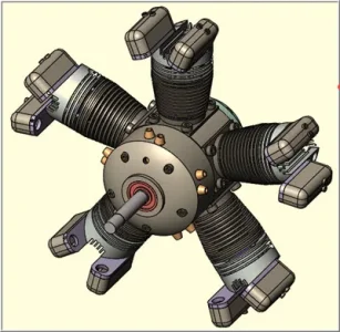
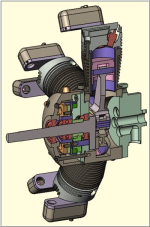
Some work-in-progress pics of my current project. It’s a 5-cylinder 4-stroke model radial engine, 24mm bore x 22mm stroke 50cc total displacement. Uses RC methanol based fuel & glow plug ignition. About 950-5500 rpm. I bought (2d-paper) plans from a builder in Germany. This is my first attempt at anything like this. But basically model engineering / engine building is my longstanding dream / justification for metalworking machines.

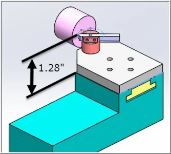
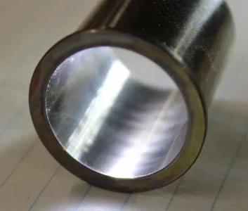
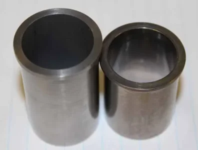
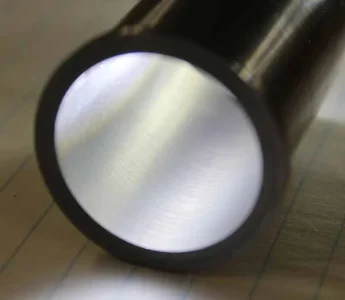
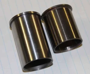
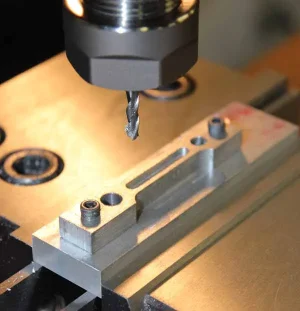
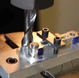
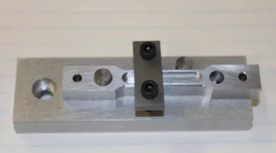
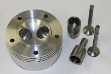
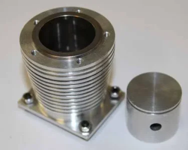
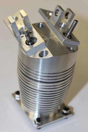
I set a goal to make one complete cylinder stack ‘prototype’ & the related jigs/fixtures. If that pans out without too many ulcers I'll proceed on remaining cylinder replication mode & then crankcase etc. A cylinder stack means cylinder barrel + liner + piston + head + valve cages + valves + springs+ rocker perch/arm/cover assembly, inlet/exhaust fittings…. Many engine builders prefer to start with the ‘big chunk’ (the crankcase) & work their way outwards. But I’ve also noticed 90% of issues are lurking in the fiddly bits, particularly valve seal. So I’m attacking it from the other end. Wish me luck.
 

Attachments

  • IMG_0606_edited-1.jpg
    IMG_0606_edited-1.jpg
    35.9 KB · Views: 58
  • IMG_0608_edited-1.jpg
    IMG_0608_edited-1.jpg
    38.1 KB · Views: 62
  • IMG_0613_edited-1.jpg
    IMG_0613_edited-1.jpg
    51.3 KB · Views: 61
Last edited:

Janger

(John)
Administrator
Vendor
Serious work there Peter! Will it look like an aircraft engine when completed? Was this what you brought to protospace the tour evening? I missed your intro...
 

PeterT

Ultra Member
Premium Member
Yes it will look pretty much like a reduced scale aircraft engine in overall layout, less some typical FS ancillaries like distributer, magnetos oil/fuel pumps etc. Glow plugs simplify the spark ignition complexities. The front crankcase chamber contains splash oil bath for planetary gears & timing cams & methanol fuel has a bit of oil in it. This mitigates oil pump system. Yes I brought some of the cylinder parts to the first meeting at Protospace.
 

Attachments

  • 7-19-2015 0001.jpg
    7-19-2015 0001.jpg
    44.5 KB · Views: 35
  • 7-19-2015 0002.jpg
    7-19-2015 0002.jpg
    63.5 KB · Views: 37

Alexander

Ultra Member
Administrator
It is a little hard to tell on my phone. Is that the OS liner in your cylinder? Are you going to buy the liners from OS or are you machining them from scratch? That thing is a piece of art. Nice work so far.
 

PeterT

Ultra Member
Premium Member
Hi Alex. Good eye. That is indeed the OS-56 liner stuck in there for picture taking purposes. The OS liner can't be used though, they need to be longer & some other features on the skirt to allow rod clearance. I've made 2 prototype liners (not shown) & they turned out well. The ID's are lapped within 0.0005", a whole procedure unto itself. The plans were a bit evasive on how the liner was fit into the cylinder barrel ID. I first thought I would (heat) shrink them. That part is relatively straightforward, but I was more concerned about future liner removal if necessary. Otherwise the whole assembly has to be tossed if the liner gets worn or scratched. This requires tighter tolerance control because the aluminum cylinder must sufficiently expand more than the steel liner since they are both mated going in the oven together. Typical RC liners are slip fit into the crankcase & I thought that was a better route.

So the OS liner was purchased as a glorified measurement gauge to serve a few purposes: it just so happens to have the same nominal bore as the radial design. It will act as a plug gauge so my cylinder ID boring for correct slip fit. Mostly it gives me accurate bore ID dimensions/finish to replicate because my plan is to use commercial rings for the first iteration. Home made (cast iron) piston rings at this scale are very finicky to make. They are about 0.045" x 0.050" in cross section & involve a series of jigs & fixtures & heat treating. I want this first engine to run & rings are crucial to success. So I will make my own liners & pistons (replicating the commercial dimensions), but use commercial rings initially. If that pans out I will then make my own rings.

So the only purchased bits are rings, bearings, fasteners & probably the carb initially to get sizing about right. The rest is all bar stock, no castings.
 

PeterT

Ultra Member
Premium Member
Thanks. Lately its been 3 steps forward, 2 back. I was having some difficulty with the valves sitting flush in the combustion bowl. This was a function of how 3 individual parts are machined & then mated to one another (the head, the valve cage & valve itself). I wont go into boring detail, but I had to chase down contributing culprits one by one (and learned quite a few things along the way). For example <newbie alerts>
- end mills don't actually cut a square bottom hole, they have an angle relief in order to cut. Doh! there's a few thou.
- a square shoulder part turned on a lathe is not 90-deg like the drawing. Of course it has a fillet from cutting tool nose, so the opposing face requires chamfer to accommodate. Doh! few more thou.
- another culprit was my first attempt at making the hemi-shaped combustion chamber. I first tried by grinding a form tool from 5/8" HSS & plunged it axially to a defined depth. It looked good initially & seemed to measure up, but it wasn't actually quite as 'hemi' as I thought once the cages & valves were in. I also wasn't thrilled with pushing a tool in like this because it has a lot of cutting edge.

So I came up with this gizmo to cut hemispherical dome shape combustion chamber. Its a similar principle to those ball making accessories for lathes, but just dedicated to this particular task & geometry constraints. I have to remove the tool post to install + also required a new T mount plate. But it worked out in the end. I just take light, progressive skim cuts to total depth. Its more controlled, accurate & better finish. Maybe I should make one of those ball cutting jigs one day.

IMG_0624_edited-1.jpg IMG_0625_edited-1.jpg
 

BradH

Member
Wow...! I was going to ask how you cut the bowl... I am interested in your cutter. I have been giving thought to a similar tool with the intent of creating a large groove in a pulley for a friend. I haven't gotten the material yet - supposed to be hard plastic. The groove is to be a 7/8" diameter half-round... to mesh / engage some bar or pipe. I figured mounting a 3/4" bar with a HSS tool bit like you did would do the trick, but hadn't figured the mounting geometry. May be coming to pick your brain about that...

Your design looks much more elegant and simple than anything I had thought up so far.

Brad.
 

PeterT

Ultra Member
Premium Member
Brad, I made my radius cutting jig more as an experiment & using materials I had available. The downside is, its kind of limited to the range. In hindsight & now that I've used it a bit, I think a dedicated radius turning accessory like these (links) would have accomplished this job plus a range of future turning applications; both In-ees (internal groove type profiles ) and Out-ees (ball type profiles). I kind of like the way they used an insert sitting on a perch. Once the height is established, you are done. And I think you just flip the perch orientation for inner/outer range. On the other hand, HSS is cheap & allows latitude to grind different relief profiles, nose radius etc. Maybe making a sister perch with slot for HSS/tool blanks? Mine is kind of simplistic, the HSS blank also serves as the handle. Not really optimal or as safe, a proper handle is better.
http://bedair.org/Ball/ball.html
http://www.micro-machine-shop.com/ball_turner.htm

My bottom detail pic maybe deserves some explanation & I think the ball turners do something similar. The cap screw/washer draws in the rotating cutter body against the plate in order to adjust snugness. It needs to swivel freely, but no play. I made a brass shim washer to take the slide motion. The screw is set with blue locktite to hold the setting, or it can be tweaked later as required.

Another consideration is the lathe height. I should study those ball turner designs more but I think the compound is completely removed & ball turner mounted to Y cross carriage. I guess I could do that too, but was trying to limit setup it to just removing the dovetail tool post. But that didn't leave me a lot of room to center height (~ 1.28" on my lathe).

I haven't done a lot of plastic turning, some nylon & UHMW. I seem to recall it likes a very sharp cutting tool & more back relief tool. It cut very smooth & nice finish. Just have to watch the swarf can bunch up & tangle.
 

Attachments

  • 8-3-2015 0004.jpg
    8-3-2015 0004.jpg
    31.4 KB · Views: 17

BradH

Member
Hi Peter:

I have seen this type of ball turner before... I have intentions to build a different type to make handles etc. But I think your simple cutter holder will serve as a good basis... my job is simple, cutting a soft material, and a 1-off... so lots of good thing there...

My center height is higher, so may need some sort of collar to hold it more rigid.

Thanks for sharing.

B.

PS - this is the type of ball turner I am looking at making...

http://www.conradhoffman.com/ballturner.htm
 

PeterT

Ultra Member
Premium Member
Made a bit of progress with the rocker perch, valve cover & spring retainers. Then I hit a small obstacle. The design calls for a very particular metric spring spec (wire diameter, coil ID/OD & free length). I located some imperial springs out of US that looked like they would work by specs, but turns out they were just a tad too large, rubbing & hanging up the valves a bit. Accommodating this larger size was going to a PITA because it affected quite a few inter-related parts & features. Some net hunting & I found some springs from German supplier, nice quality, cheap but holy friggen nightmare ordering. They don't do Visa or Paypal or Money orders or Checks or Bank drafts or Beaver pelts... Only wired funds. Ugh. Anyway, finally landed. They are perfect & now can proceed again. My next option was to wind my own & I may actually experiment with that a bit on the side.
IMG_0628_edited-1.jpg IMG_0629_edited-1.jpg IMG_0634_edited-1.jpg IMG_0642_edited-1.jpg IMG_0643_edited-1.jpg
 

PeterT

Ultra Member
Premium Member
Available shop time has been scarce for me lately but I've been working on some liners, trying different materials & methods. The thing to know is ID's have to be within +0.0000 -0.0005" of a target dimension (0.9445") in finished state and with the right surface finish. So lathe boring is really a roughing stage to get them about 0.002" under dimension, then they are lapped. I first thought I could ream as the last lathe operation to correct any barrelling & get decent pre-lap finish. That aspect worked pretty well, but what I did not count on is that the closest reamer size still left me 0.007" under to go. Well, in the lapping world that's equivalent to trying to take off 1/8" of oak with 220 sandpaper. So the trick is to hit the pre-lap dimensions with boring tools alone, nice & parallel & minimal tooling marks. Lets just say this has been a 'learning experience'. My first one was 12L14 which machines quite nice. But I has a tendency to get rust blotches & methanol fuel will accelerate this. It also can go 'Bwoing' a bit just sitting there (stress relieving). Cast iron is another favorite my model engineers. It has to be close grained stuff which is not easy to source around here. I finally got a 1-foot chunk of appropriate diameter out of USA... along with the UPS spanking. Despite no prior experience, CI is actually very neat material to machine. Messy but it cuts & finishes quite well.

This shows my (longer) CI liner against a commercial RC liner for target analog. It has seen the first lapping pass of 400 grit, maybe removed 0.0005" off the top of the hills so to speak. You can still see some tool cutter trough shadows but you would be hard pressed to actually feel them. The silky matt finish & longitudinal reflection lines is supposedly correct. It came out nice & parallel but there is a whole rigmarole to accurate measurement. So another 0.0015" to go with progressively finer lap & then then final crisscross surface honing. The commercial liners are electro hard chromed & ground so way outside the scope of my shop abilities, but many successful engines have been built with these home methods. Lapping is mind numbingly slow & crawls to turtle pace once in native material. You lap, clean, measure, re-charge... and then repeat over & over. Unfortunately what makes CI a good liner material for its hardness properties also makes it even slower lapping. Ugh. I'm also going to try some 1144 stress proof which some guys have claimed good results. The journey continues...
 

Attachments

  • OS-56 chrome bore.JPG
    OS-56 chrome bore.JPG
    39.4 KB · Views: 12
  • 400g lap step-1.JPG
    400g lap step-1.JPG
    35 KB · Views: 12
  • radial vs OS-56 p2.JPG
    radial vs OS-56 p2.JPG
    34.6 KB · Views: 13
  • radial vs OS-56 p1_edited-1.jpg
    radial vs OS-56 p1_edited-1.jpg
    45.9 KB · Views: 12

PeterT

Ultra Member
Premium Member
The 5-cyl radial has 4 identical link rods & one master rod. I'm figuring out link rods & related jigs now. These prototypes have errors, but show the general procedure. They are fussy little buggers with several sequential machining operations. But I am learning lots. One jig is to do the dog bone profiling & center flute on both sides. Another jig is for doing the round-over operation on both ends using a 4" Sherline rotary table. I'll take some pics of the RT baseplate I made, it gets held in my mill vise. I'm actually really impressed with the Sherline, its very accurate & functional & suits these smallish parts.
 

Attachments

  • IMG_0712_edited-1.jpg
    IMG_0712_edited-1.jpg
    46.1 KB · Views: 17
  • IMG_0710_edited-1.jpg
    IMG_0710_edited-1.jpg
    45.4 KB · Views: 17
  • IMG_0707_edited-1.jpg
    IMG_0707_edited-1.jpg
    24.4 KB · Views: 17

Geoff

Member
Very cool Peter! You are an artist! Lots of interesting setups and jigs! I was also going to ask about the liner. How are you honing it to tolerance? Are you using a commercially available hone or did you make something? Are you using stones or a lapping compound?
 

PeterT

Ultra Member
Premium Member
Thanks for the nice words. The final bore diameter/geometry/finish is accomplished with a brass lap. Some guys make their own but I found the Acro works well - relatively inexepensive & replaceable barrels.
http://www.acrolaps.com/
The stones like the sprung brake cylinder jobbies don't do well in this environment. They remove material better but at the risk of losing dimensional control & particularly bell-mouthing effect. They 'look' like the big boy Sunnen hones, but lack a lot of the control mechanism & stone quality. My understanding is they are more for deglazing/resurfacing hardened bores & typically longer, so less risk of messing things up. As I mentioned upstairs a few posts, lapping is a very accurate & controlled process but excruciatingly slow & somewhat messy process. You really need the lathe operation bored within a couple thou & good finish. Any more undersize & you just wear out the lap & are there forever. Especially cast iron. In the real world its machining > grinding > lapping (usually also because hardening is in there too). So going from machining > lapping is kind of missing an in between step. Tool post grinders are probably the way to go but they are not for the faint-of-wallet.

What I discovered most model guys are doing is getting the bore to 'whatever'. IOW they don't care if its 0.999" or 1.001" as long as the finish & bore geometry (roundness & parallelism) is there. So they lap multi-cylinders in sequential batches ending with the same tool/setting. However, now you must size both ring & piston to suit this bore. In my case its the reverse: I want to use a commercial ring, so that means my bore + finish must arrive at a specific dimension like 1.000" with very low tolerance. Making rings is a bit of finicky operation & challenges even the gurus. A 1" nominal bore translates into a ring of ~0.050" in cross section. They are cast iron so quite fragile. The machining isn't too bad but they need to be heat set on a pin/jig to a specific dimension & temp. This heat set alteration yields the appropriate radial sidewall force for gas sealing when compressed in the bore. http://homepage2.nifty.com/modelicengine/h9110101.htm
Eventually I want to get there, but for this first engine I figured treat myself to commercial rings for all of $10 each & use that as base line for running. In hindsight its choose your poison.
 

Rudy Pekau

Brand New Member
Thanks for the nice words. The final bore diameter/geometry/finish is accomplished with a brass lap. Some guys make their own but I found the Acro works well - relatively inexepensive & replaceable barrels.
http://www.acrolaps.com/
The stones like the sprung brake cylinder jobbies don't do well in this environment. They remove material better but at the risk of losing dimensional control & particularly bell-mouthing effect. They 'look' like the big boy Sunnen hones, but lack a lot of the control mechanism & stone quality. My understanding is they are more for deglazing/resurfacing hardened bores & typically longer, so less risk of messing things up. As I mentioned upstairs a few posts, lapping is a very accurate & controlled process but excruciatingly slow & somewhat messy process. You really need the lathe operation bored within a couple thou & good finish. Any more undersize & you just wear out the lap & are there forever. Especially cast iron. In the real world its machining > grinding > lapping (usually also because hardening is in there too). So going from machining > lapping is kind of missing an in between step. Tool post grinders are probably the way to go but they are not for the faint-of-wallet.

What I discovered most model guys are doing is getting the bore to 'whatever'. IOW they don't care if its 0.999" or 1.001" as long as the finish & bore geometry (roundness & parallelism) is there. So they lap multi-cylinders in sequential batches ending with the same tool/setting. However, now you must size both ring & piston to suit this bore. In my case its the reverse: I want to use a commercial ring, so that means my bore + finish must arrive at a specific dimension like 1.000" with very low tolerance. Making rings is a bit of finicky operation & challenges even the gurus. A 1" nominal bore translates into a ring of ~0.050" in cross section. They are cast iron so quite fragile. The machining isn't too bad but they need to be heat set on a pin/jig to a specific dimension & temp. This heat set alteration yields the appropriate radial sidewall force for gas sealing when compressed in the bore. http://homepage2.nifty.com/modelicengine/h9110101.htm
Eventually I want to get there, but for this first engine I figured treat myself to commercial rings for all of $10 each & use that as base line for running. In hindsight its choose your poison.


Interesting project,being a former RC model builder and flyer.

There is more out there: I am involved in a Toroidal Rotary engine project, several prototypes have been built.You can see an expander engine running on compressed air on youtube : type Roundengine July 2011
It was meant to go into an automotive hybrid with waste heat recovery. Wonder if there is anybody out there in getting involved ?

Any comments ? email to pekaudr@shaw.ca
 

Jyman

Member
Hey PeterT

That's a nice looking engine your building, I would love to build a radial engine at some point. where did you get the blueprints from? And what did the plans cost you?

Jon
 
Top