• Spring 2024 meetup in Calgary - tentative date Saturday, April 20/2024. Other regions are also discussing meet ups. If you want one in your area get going on organizing it! discussion
  • We are having email/registration problems again. Diagnosis is underway. New users sorry if you are having trouble getting registered. We are exploring different options to get registered. Contact the forum via another member or on facebook if you're stuck. Update -> we think it is fixed. Let us know if not.
  • Spring meet up in Ontario, April 6/2024. NEW LOCATION See Post #31 Discussion NEW LOCATION

Quick Change Tool Post Mounting ...

Janger

(John)
Administrator
Vendor
Hi Everybody,

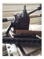
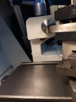
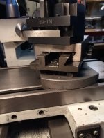
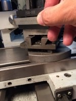
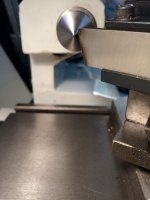
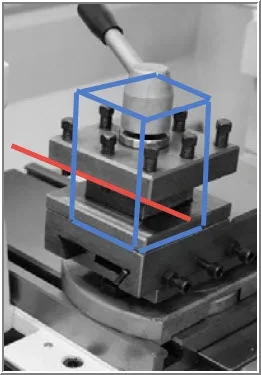
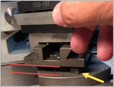
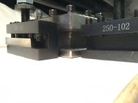
I finally have my quick change tool post (AXA size, wedge type) from Accusizetools.ca mounted on my lathe. This replaces the stock 4 position turret tool post. It works well, I am quite pleased. However, since my lathe (CX701 from BusyBee) has kind of a different type of compound the tool post does not mount in the normal manner with a T-Nut.. This has led to problem where the tools can't be lowered quite enough to get to the centre of work in some cases. e.g. the parting tool and 1/2" bits. 3/8" bits are fine. See pictures.

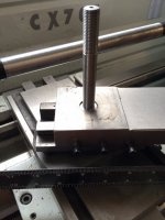
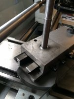
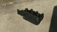
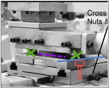
I could make a irreversible modification to the compound and remove about 1/2 inch of material from the end of the dove tail slide. This would allow the tool holders to be mounted lower and solve the centre height problem. Two variations. One I could take all the material off and make it square. Options two perhaps just remove 3/8" or so leaving some material for rigidity. I drew a red box around where I could remove material.

Thoughts?
 

Attachments

  • toolpost 1.jpg
    toolpost 1.jpg
    117.3 KB · Views: 38
  • toolpost 2.JPG
    toolpost 2.JPG
    126.3 KB · Views: 36
  • toolpost 3.JPG
    toolpost 3.JPG
    133.5 KB · Views: 37

PeterT

Ultra Member
Premium Member
I was going to say your issue looks to be confined to what I think is a parting blade / holder assembly? That's actually somewhat common if you buy a blade assembly that is vertically too tall. I have a similar Asian toolpost, a 200-series (which I think is a BXA equivalent) on a 14x40 lathe. On the typical HSS style parting blade holder, my max blade height is 11/16". I cant (easily) use 1" blades without modifying the tip to effectively lower the center. Some people grind a gentle scallop or relief to do this, but I would thing relatively small amounts otherwise it defeats the purpose of a tall blade. The bigger issues are the insert style or carbide tipped tools because the holder assembly all kind of ties into the blade dimension. In those cases I've seen people make their own holder so the blade is lowered.

But what I'm more concerned is you say you cant use 1/2" shank tools, only 3/8"? That would be quite limiting IMO & maybe worth a re-think of the compound or tool post. I'm not that familiar with the lathe, what is the nominal swing? can you take a pic with 1/2" shank tool in the holder as close to center as you can?
 

PeterT

Ultra Member
Premium Member
Hmmm.. I wasn't familiar with that tool post & maybe misspoke. If its this one
http://www.accusizetools.com/0250-0...rning-facing-holder-quick-change-tool-holder/
... they call it 250-series for 6-12" lathes. If I read the shank capacity correctly, they say 7/16" (0.4375"). But on my 200-series tool post which I think fits the B-type holders from Aloris etc, the holders accept up to 5/8" shanks. I thought 100-series was for this size of lathe, but even that typically accepts 1/2" shanks. You might have to call Accusize to confirm.

In Travers catalog (link) you can punch in the desired shank sizes for different styles like straight turning, parting etc & it shows you what holders match. Again, they seem to correlate to my 200-series specs.
http://www.traverscanada.com/quick-... post&style=Boring%c% Turning & Facing Holder
 

Jwest7788

Joshua West
Administrator
If you haven't invested in too many tool holders already, then "you could also machine some new holders for your post." seems like the right suggjestion.

It will make a good project, and then you'll never have to buy another tool holder. (Make as many as you need)
 

PeterT

Ultra Member
Premium Member
Reading back through my post, I think my point was maybe unclear. Making or modifying a tool holder specifically for the parting blade is a viable option. It seems to be a common issue for hobbyist lathes. The blades tend to be on the smallish size (vertically), which then kind of affects max dia they can cut with rigidity because of how far they extend.

But a bigger potential limitation of that particular tool post model if (I understand correct) is 7/16" max shank size in the basic tool holder. That seems to be an oddball (reduced) dimension for that size & IMO can limit you to a lot of tooling options that is nominally 1/2" shank. I'm talking about insert cutter tooling primarily, not HSS blanks. The thicker the shank, the more rigidity & usually more common selection of inserts in that range. Yes, you can get smaller ones, probably 3/8" is next size down, but I'd rather have the optionality. Also you might have a similar problem trying to fit say a knurling tool (also 1/2" shank typically). Yes, one could make tool holder bodies to suit & would be a great project. But for 35$ a pop, dovetailing, ideally good quality steel, tapping holes... up to you. Or, depending on block size, maybe easier to mill out the gap as long as you have enough meat left.

What I was suggesting is comparable brands of toolholders seem to not have this limitation. Punch these part numbers in the KBC search box for example: http://www.kbctools.ca/
1-459-500 = the 100-series toolpost set for "up to 12" swing lathes (that's kind of similar to the Accusize, no?)
1-459-101 = the standard turning facing holder #1 that goes with this set (100-series). Notice its toolholder gap accommodates 1/2" shanks. I think these are clones of Aloris 'A' but not sure.
So I'm saying for much the same kind of toolpost, you get bigger shank capacity.

btw - KBC describes a range recommendation in the clone toolpost kits, basically related to swing or center height: "up to 12", "10-15", "13-18", "14-20". And that corresponds to the 100,200,300... type series which I believe is Aloris A,B,C... Hopefully I have this right. If someone more experienced has comments, please chime in.
 

Janger

(John)
Administrator
Vendor
Hey thanks for the good ideas. I didn't think of modifying the tool holders. The tool holders are a standard size and will accept 1/2" tool or perhaps a bit larger. The problem is the tool holder can only slide down the tool post until it hits the compound. This is the limiting dimension. In the photo you can see 3/8 bit just below center, and the tool holder hitting the compound. It's as low as it will go. Second image shows this more clearly. Third picture shows the 1/2 bit too high. It's above center about 0.1". Pic 4 shows parting blade above by 0.15". The parting blade is a 3/4".

I think probably the least drastic solution is to trim 0.15 off the bottom of the tool holders. If that is a poor answer I'll have to think about what else to try. Good suggestions! Thanks !
 

Attachments

  • image.jpg
    image.jpg
    108.9 KB · Views: 31
  • image.jpg
    image.jpg
    149.8 KB · Views: 32
  • image.jpg
    image.jpg
    148.5 KB · Views: 31
  • image.jpg
    image.jpg
    90.4 KB · Views: 29
Last edited:

Tom O

Ultra Member
So here is a thought why not machine a holder 1/2" or whatever that would clamp into the original one essentially making the holder part of the tool?
 

Jwest7788

Joshua West
Administrator
So here is a thought why not machine a holder 1/2" or whatever that would clamp into the original one essentially making the holder part of the tool?
Thats a good idea, Use the tool holder to hold a home-made tool holder. Would rigidity losses be a consideration?
 

Tom O

Ultra Member
I would not think it would affect it that much it would be machined square so it butts against the original mount so stick out would be around 1/2" to 3/4" depending on cutter left, right, or center so for straight in plunges it would be fine now whether or not it could rotate for a bevel Im not sure but could switch to another tool holder set up for the original size.
 

PeterT

Ultra Member
Premium Member
Its almost as though the whole compound assembly is sitting 'a little' high relative to the swing capability of this lathe. That's not necessarily a bad thing, but just saying the typical tool post selection guidelines from tooling catalogs might not necessarily be the best fit. I guess you could trim off the bottoms of the tool holders if you are that close. If you were to find a next-size-smaller toolpost assembly, they might be sized overall say 80% of the 200-series & amount to the same amount of net material dimensionally & strength wise anyways.

I found this vid. there are 2 parts. Its not super informative, but might give you some more insight. One of the commenters mentioned an alternative tool post.

So back to Accusize, is this the smallest toolpost they offer of this size, or is there one under?
 

Alexander

Ultra Member
Administrator
This is what I did to make my part off blade fit I attached a photo. I ground about .150" off the top of the blade. The top of the blade was not a flat cutting edge from factory anyways. It was formed to stay in the holder better. I didn't want to mill any off the holder unless I had to. I am a fanatic about rigidity. It is always the most important factor in machining. Milling some of the bottom of of turning tools will be totally fine. I would be concerned about rigidity of the home made tool holder inside a tool holder idea. I think milling some off the tool holder opposite the red box in the first post would be OK. As long as it doesn't leave too little support for the bottom of the holder.
 

Attachments

  • IMG_20150615_103857872.jpg
    IMG_20150615_103857872.jpg
    115.2 KB · Views: 13

kylemp

Well-Known Member
Cutting material off the compound from that red box doesn't make sense to do.. you would end up having to undo the compound to rotate it into position every time. You are either going to have to cut the compound height down (which probably isn't really an easy option but in all likelihood is the surface that should be brought down), skim some material off the bottom of the holders, or take some material off of the parting blade and anything else you are intending on using in there thats above center height. Sorry to see that, such a pain in the ass when its supposed to be easy!

Also, I would think that rigidity is a relative concern.. if you are taking cuts right now that are causing issues with chatter because the tools mounts are flexing away then yes, it probably will be an issue. If your machine doesn't have the power to take heavy cuts with the tooling you are running that cause that kind of issue then no, it probably wont matter. It's all going to come down to how hard you actually run your machine, and you might have to back off a bit on how aggressive of a pass you can take.

Looking back at your pictures though the compound mount might be the easiest place to get the height down. I'm not sure if there is actually a place you could do that.. just looks quite high in that area.
 

PeterT

Ultra Member
Premium Member
I'm not really familiar with this particular lathe, so take this FWIW. But I can somewhat visualize what might be going on in terms of the height issue. I think
a) they kind of designed it around their stock tool post which sits centered a bit low relative to the more modern typical wedge/piston style post. Maybe 1/2" there?
b) the way the compound assembly sits perched up to (presumably) allow wrench access to the 2 hold-down nuts. That's probably another 1/2" there?

There's probably not much you can do about a). Skim off some cast iron ... Yeesh. Anything that reduces mass & strength is a bad thing. Maybe if you could buy a sacrificial one inexpensively to try..
But b) has me mystified a bit. Is the purpose of the nuts just to secure the top compound assembly via the T-nut slots? What about if that was reversed, as in cap screws going down into T-nuts & the corresponding holes in the base was countersunk so capscrew heads were submerged? You would also have to trim the boss down (I suspect the nuts are why they made it thickish anyway). But the only way this could work is if you can remove the toolpost & top assembly to get access to the new capscrews. I cant quite visualize that far. Maybe these sketches will help. Don't cut anything & blame me! :) But I also cant imagine you are the first person to have experienced this issue. There must be others on the net. Kind of unfortunate, it looks like a nice lathe without that little irritation.
 

Attachments

  • 7-15-2015 0001.jpg
    7-15-2015 0001.jpg
    22.5 KB · Views: 13
  • 7-15-2015 0000.jpg
    7-15-2015 0000.jpg
    44.2 KB · Views: 16
  • 7-15-2015 0005.jpg
    7-15-2015 0005.jpg
    23.6 KB · Views: 18

kylemp

Well-Known Member
I found the diagram for the lathe and it looks like the tslot nuts also are the clamping mechanism for the angle adjustment of the compound so making a modification there might not work. It looks like the top of the compound had extra material on it though, which is why I thought skimming it down the little bit needed might work. I agree that a sacrificial one would be a better test though..
 

Janger

(John)
Administrator
Vendor
Really I think the whole compound setup is not the greatest. It is not all that rigid. ok for home but it could be improved. It is probably a reasonable match for the rest of the machine, mass, the ways, motor HP etc. Anyway...

I milled off 0.1" of the bottom of one of the tool holders, put in a 1/2" bit, and turned some awful black pipe I picked up for cheap. Works well! Rigid and good turning results. The wedge quick change tool post is a marked improvement over the four turret post. I was not expecting that, I thought I was buying convenience but it does seem to work better as well. Pretty good upgrade. I'm uploading a video of fly cutting the tool holder using this home made power feed I made. You will find it in the Projects section.

I think there are other things I could do, more complicated things, but at $20 a tool holder milling them down seems like the simplest low risk solution. Thanks for all the discussion and ideas!

Pic below . Left, original tool holder, middle back original four turret, right is the milled down tool holder.
 

Attachments

  • image.jpg
    image.jpg
    89.7 KB · Views: 18

PeterT

Ultra Member
Premium Member
Looks good. Simple is best.

Another thing you might find if your tool holders are anything like mine, despite pretty nice dovetail grinding & pretty reasonable cost, they supply some real fromage set screws. I was never really sure if they were metric or imperial until I measured the thread because the metric hex key fit so bad & was rounding over the hex to the point one became stuck. I was able to remedy with penetrating oil & next size imperial hex key to remove. Consider upgrading to some decent screws, they are inexpensive, much better quality & deeper hex sockets. These tend to fill up with chips which doesn't help matters anyway. Mine were M8 x 1.25 x 30mm I believe. You cannot replace these with 'headed' socket cap screws, at least on the inner holes, because the head conflicts with the vertical adjustment wheel. I also bought some shorty set screws 20 & 25mm length for thicker shank tools so less screw protrudes. I cant really see a reason why the originals have turned down threads on the ends. In fact its silly IMO on thick shanks because you have less thread contact. My plain set screws worked fine. Run a tap through the existing holes too. My threads were crappy & lots of gunk in there from the blackening treatment.
 
Top