Project flycutter.

Stellrammer

Well-Known Member
That looks pretty darn nice from where I'm standing. Are heads like that cast iron?

Your flywheel haha FLYCUTTER is big & very symmetrically machined. I'm guessing its as close to perfectly balanced as practical. Once upon a time I drew up a regular flycutter in CAD, the kind with the bevel bottom & cutter sticking out the side & computed the resultant center of mass. It was off axis as expected, but the question becomes does that adversely affect finish (compared to the other cutting tool factors). If the spindle bearings contain the imbalance load I cant see it being a problem. If one had a big heavy + unbalanced + high RPM setup, that would be an issue. Like grinding wheels which are relatively light but high rpm.

View attachment 31337
What a great result, I couldn’t come close to that on my poor abused Excello.
 

PeterT

Ultra Member
Premium Member
Some of the WD40 Corrosion Inhibitor prices were crazy when I looked, but maybe in the wrong places. Our climate is pretty dry by comparison - good for tools, bad for skin. But I did a test on some freshly machined steel coupon slugs in baggies. #1 metal with a spritz of water (showed rust freckles as expected). #2 this AERVOE from KBC (no corrosion). #3 Canadian Tire gear oil off my shelf (no corrosion). I've meaning to try Fluid Film since I bought some. I find it to be kind of snotty stuff & not easy to remove, but maybe that's by design.

 
Last edited:

little ol' e

Jus' a hobby guy
Fluid Film works. No doubt about it. But there are better products out there. Trouble is that they cost even more.


If you think Fluid Film is expensive, try WD40 Corrosion Inhibitor. So far it's my leading favorite but that story has yet to be told.

Thanks, I haven't tried any of the WD40 products, I will be putting that on my next shopping list to give it a try. Cost aside really, if it works.
 

Susquatch

Ultra Member
Administrator
Moderator
Premium Member
Some of the WD40 Corrosion Inhibitor prices were crazy when I looked, but maybe in the wrong places. Our climate is pretty dry by comparison - good for tools, bad for skin. But I did a test on some freshly machined steel coupon slugs in baggies. #1 metal with a spritz of water (showed rust freckles as expected). #2 this AERVOE from KBC (no corrosion). #3 Canadian Tire gear oil off my shelf (no corrosion). I've meaning to try Fluid Film since I bought some. I find it to be kind of snotty stuff & not easy to remove, but maybe that's by design.

@Dabbler and I set out to do some evaluations that would take into account both western and eastern corrosion differences. Originally, we wanted to find and evaluate bulk VCI's. But that objective fell apart after learning that there were none that would satisfy our test environment parameters.

We have yet to complete and agree on the rest of the test results. That will have to wait till this coming fall. For now, I can say that success is not cheap. The WD40 Corrosion Inhibitor is very costly for a very small can. But in our extreme test, it is providing superior performance. So is Liquid Wrench Corrosion Inhibitor.

We will be reporting more fully later this fall. Not much more to be said right now but didn't want to hold out on what we can say so far.
 

Dabbler

ersatz engineer
I'm waiting for "Project farm" to test rust inhibitors. That video was great, but I love 2nd opinions...
 

John Conroy

member
Premium Member
A little over 20lbs, OK.
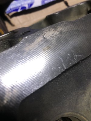
I noticed the chip color, load and formation. I noticed on this project you don't seem to be using coolant;)

My guess would be, you will be running lower than 350 RPM in time with different inserts when machining cylinder heads perhaps? Interrupted cuts are a bugger in those head castings.
Do you feel as thou the rotating weight mass could eventually do harm to your spindle, bearings or housing over time?

Fluid film has gotten expensive these days, being a car guy myself.
I use mine sparingly these days. I picked up a project Olds in 2021 on the cheap, and its still covered in fluid fill. Probably 1 of those projects that will be sitting long after I kick my clogs..

My brain is telling me, I've got to ask....
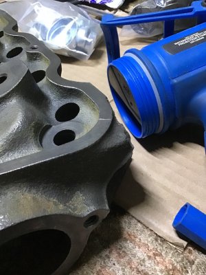
How much your taking from those Chev heads ? A compression boost ? Or just clean up for new head gaskets?
The head I showed in the videos is a scrap one but it had the same problems most heads develop, surface flatness out of spec and corrosion that develops around the coolant passages. That's what I want to correct. Probably never have to removed more than .010"

I'm not worried about damaging the spindle. The mass of it will smooth out the pounding from interrupted cuts the way a flywheel on an engine smooths power pulses. Keeping the spindle fully retracted and taking light cuts I don't think any damage will occur. I think taking big cuts with my 1.5" roughing end mill probably is harder work.

Fluid film is on sale right now at Princess Auto. I also bought some of the Sea Foam rust inhibitor recommended by Fireball but haven't tried it yet. Corrosion is not much of a problem here like in more humid areas.
 

John Conroy

member
Premium Member
Thanks for the info regarding inserts. I do have one holder with a apkt milling insert I haven't tried yet. Chip load is going to be very light as max depth of cut will likely be about .005.
It seems like the world of carbide inserts is a very complicated one. I think most hobby guys try a couple of different ones and pick the one that gives a good result without thinking about all the engineering that goes into the design
Good work on that, I made a similar boring tool out of an old flywheel from a 2 Litre Triumph six., I doubt it would make a good fly cutter though, forces would work against it, a .010” DOC @.0035” feed isn’t much to contend with in a bore.
Mass and rigidity can’t be beat, size of taper and type of taper are influential. The difference between a 50 taper shrink holder and one that contacts both the flange and taper when drawn up is considerable. The ability to rough and finish while giving better tool life is apparent.
If you are going for finish, a sharp edge Milling insert with a wiper flat designated for low feed finishing will make life easier. Typically the smaller radius is on a turning insert the better the finish is going to be, but that is still a proponent of feed and depth. Ideally the radius should be buried to reduce chatter and render chip control. control the chip and you can control the finish in most materials.
You will rarely find turning inserts with a wiper flat, they don’t really work all that well in that their very nature can cause chatter if not set up correctly. You will not find an insert with a truly dead sharp edge, at the very least there is a rolled over edge from a “brush” hone that will be over a thou.
Most manufacturers will have inserts specifically for finishing, usually the ones for heat resistant alloys are edge prepped to be sharp and have wear resistant coatings. The sharper the edge the weaker it is though.
The problem with edge preps , especially in the ultra cheap offshore pressed ones, is inconsistency or just plainly poor quality control. If you are dealing with an insert that has an .008” edge prep/land , anything under an .008 feed is now negative rather than a positive rake, causing finish issues and chip control problems.
These are some of the reasons using a milling insert with a ground chip breaker is a better choice. The edge is far sharper and the radius truncated, giving not only the larger contact flat wiper but reducing cutting forces from the radius.
In short a larger radius turning insert is going to create a few issues. The rad is not likely to be buried and the edge prep is typically more negative, giving needed strength but creating more cutting forces, everything is always a compromise.
I don’t know what the state of the industry is right now as far as knowledgeable technical reps vs “sales” oriented personnel, as far as the tooling manufacturers and distributors.
It is worthwhile to culture a relationship with a rep that knows his stuff, if you have to tell someone what you need and how to get it or even what it is then you both might be disappointed.
Cheers Tim
 
Last edited:

John Conroy

member
Premium Member
That looks pretty darn nice from where I'm standing. Are heads like that cast iron?

Your flywheel haha FLYCUTTER is big & very symmetrically machined. I'm guessing its as close to perfectly balanced as practical. Once upon a time I drew up a regular flycutter in CAD, the kind with the bevel bottom & cutter sticking out the side & computed the resultant center of mass. It was off axis as expected, but the question becomes does that adversely affect finish (compared to the other cutting tool factors). If the spindle bearings contain the imbalance load I cant see it being a problem. If one had a big heavy + unbalanced + high RPM setup, that would be an issue. Like grinding wheels which are relatively light but high rpm.

View attachment 31337
The head I have is cast iron but I work on lots.of aluminum ones as well. The cast iron used in North American engines is generally very fine grain high quality stuff so it's nicer to work with than some of the offshore stuff that creates so much dust when machining.
 

little ol' e

Jus' a hobby guy
I'm not worried about damaging the spindle. The mass of it will smooth out the pounding from interrupted cuts the way a flywheel on an engine smooths power pulses. Keeping the spindle fully retracted and taking light cuts I don't think any damage will occur. I think taking big cuts with my 1.5" roughing end mill probably is harder work.
It certainly did cut well in the video,
Everything looked amazing!!
I just wasn't sure if you were planning on putting the button cutters in and milling so to speak then skim.
Geez, I'd be temper to stick a stone on the bottom of that and give it a nice Blanchard surface.
That would be an interesting test.
Good to hear you feel safe with your new tool !
That was a nice build!!
 

Janger

(John)
Administrator
Vendor
The head I showed in the videos is a scrap one but it had the same problems most heads develop, surface flatness out of spec and corrosion that develops around the coolant passages. That's what I want to correct. Probably never have to removed more than .010"

I'm not worried about damaging the spindle. The mass of it will smooth out the pounding from interrupted cuts the way a flywheel on an engine smooths power pulses. Keeping the spindle fully retracted and taking light cuts I don't think any damage will occur. I think taking big cuts with my 1.5" roughing end mill probably is harder work.

Fluid film is on sale right now at Princess Auto. I also bought some of the Sea Foam rust inhibitor recommended by Fireball but haven't tried it yet. Corrosion is not much of a problem here like in more humid areas.
I have a humidity gauge in my shop. Talk about dry on the prairie. It's reading 10% right now.
 

Stellrammer

Well-Known Member
The finish you are getting is is making me think about trying out similar operations, traditionally cast iron milling was carried out with ground, double negative inserts. I wonder whether they would hold up better under those conditions than the positive style, a lot of hammering on them ,even under light loads.
I will search through my inventory and try to find some cast iron grade inserts. I have about .065” to take off an in-line six head, don’t really want to do it .004” at a pass though.
Or just let the guys down the road at the automotive shop do it right for $100. Because cast iron dust, making a mess of the head.
 

Susquatch

Ultra Member
Administrator
Moderator
Premium Member
Or just let the guys down the road at the automotive shop do it right for $100.

Hard to beat $100 down the road. Unless it's really important to you to have the pride of doing it yourself, I'd let them do it. The setup in your shop alone will give you headaches.
 

Stellrammer

Well-Known Member
Hard to beat $100 down the road. Unless it's really important to you to have the pride of doing it yourself, I'd let them do it. The setup in your shop alone will give you headaches.
I’m on board with that program. I don’t need another squirrel to chase right now, and I do hate cast iron dust. And they have the equipment, the knowledge and they are really nice people.
You should see the horrendous machine marks on this head, from the factory, on sealing surfaces, .015” steps, areas that look like they were chiseled instead of milled.
This is on a head mfgd in 1980, when they should have known better.
 

Susquatch

Ultra Member
Administrator
Moderator
Premium Member
This is on a head mfgd in 1980, when they should have known better.

I would have thought so too. What's the engine and where was it made?

I assume domestic in 1980. But still the Mexican plants were not great even then.
 

Stellrammer

Well-Known Member
81 Mustang, 200 ci . In late 79 the 2.8 v6 Cologne engine was no longer available in qty to supply the US market, Ford switched back to the ancient 200 straight six, Lima Ohio.
 

Stellrammer

Well-Known Member
Dark times indeed.
 

Attachments

  • ACF59E73-7090-48ED-BB88-A9F656312475.jpeg
    ACF59E73-7090-48ED-BB88-A9F656312475.jpeg
    448.3 KB · Views: 10
  • 33684EE2-4114-4014-B129-116E26F67B21.jpeg
    33684EE2-4114-4014-B129-116E26F67B21.jpeg
    309.1 KB · Views: 10
Top