• Spring 2024 meetup in Calgary - date Saturday, April 20/2024. discussion Please RSVP Here to confirm and get your invitation and the location details. RSVP NOW so organizers can plan to get sufficient food etc. It's Tomorrow Saturday! you can still RSVP until I stop checking my phone tomorrow More info and agenda
  • We are having email/registration problems again. Diagnosis is underway. New users sorry if you are having trouble getting registered. We are exploring different options to get registered. Contact the forum via another member or on facebook if you're stuck. Update -> we think it is fixed. Let us know if not.
  • Spring meet up in Ontario, April 6/2024. NEW LOCATION See Post #31 Discussion AND THE NEW LOCATION

Project flycutter.

John Conroy

member
Premium Member
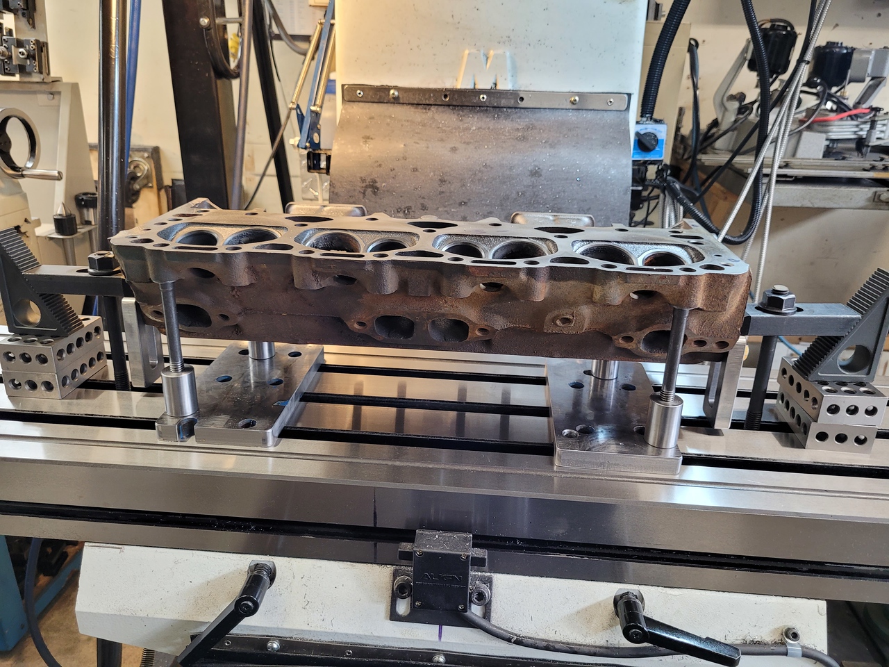
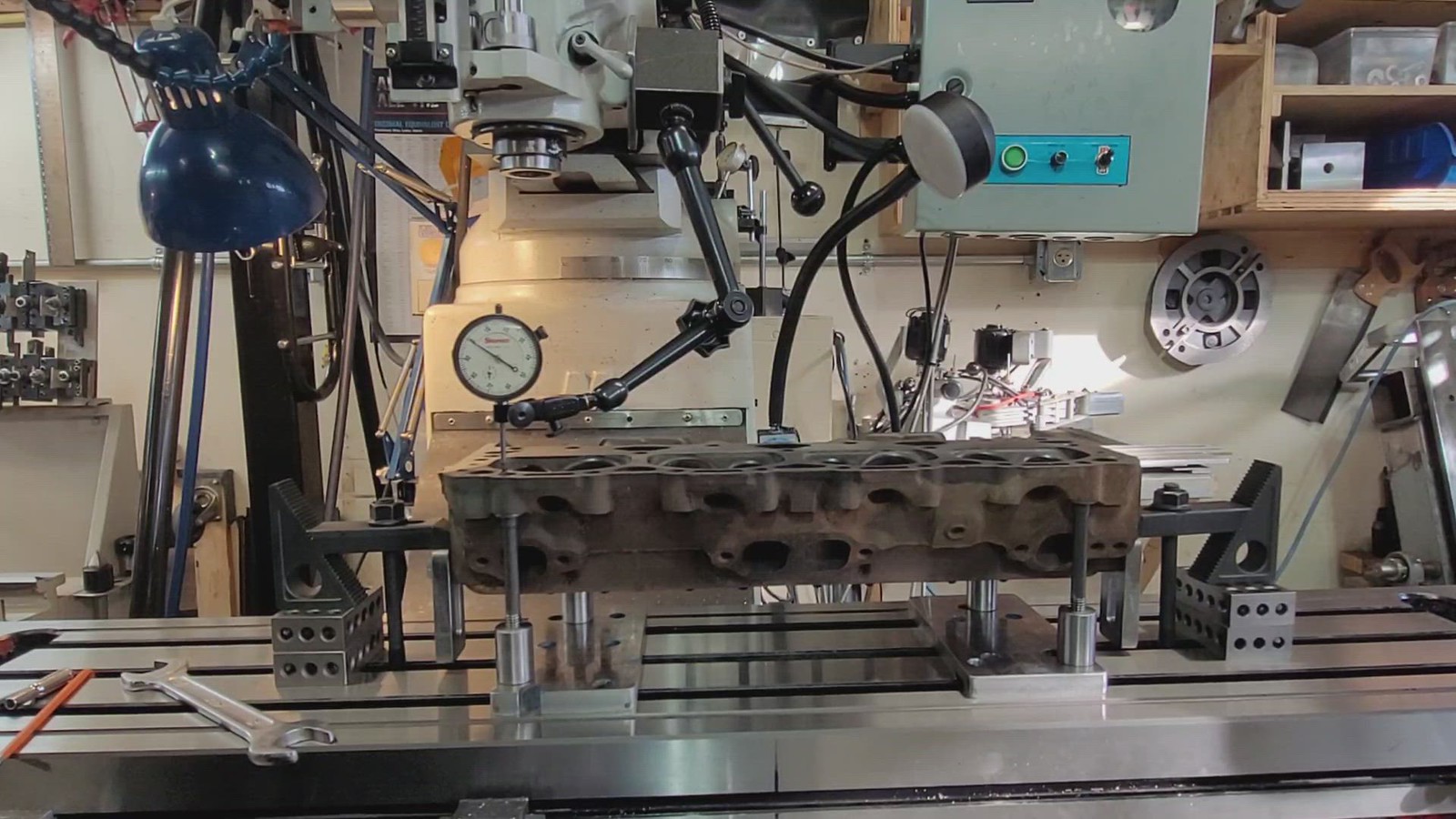
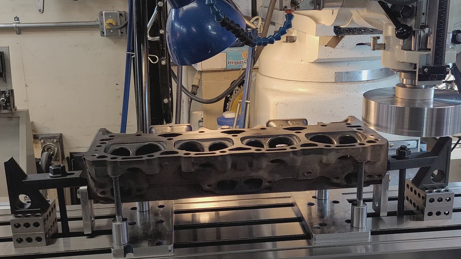
I have a flycutter that I made many years ago. It’s served it’s purpose and works OK for machining pieces less than 6” across. I have used different 5/8” shank lathe tools, both positive and negative rake with varying results as shown in these pics.


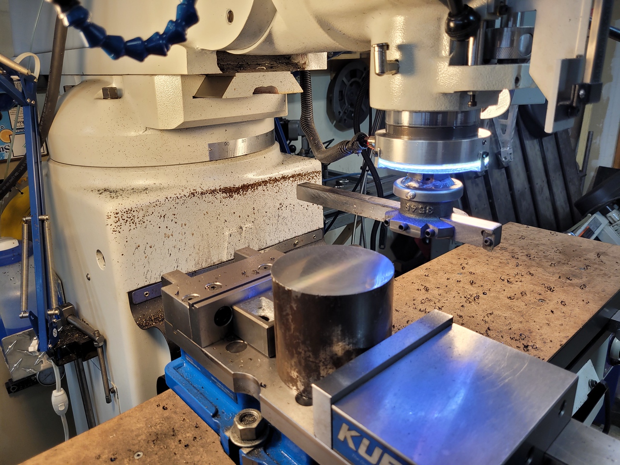
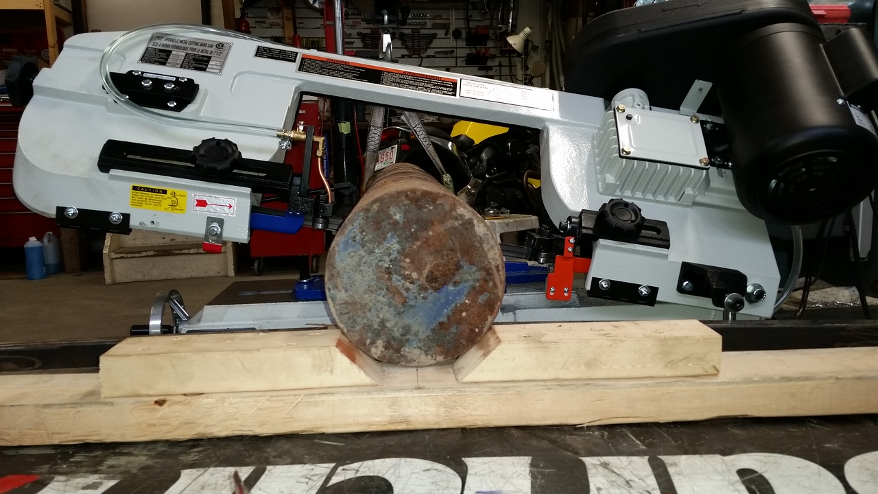
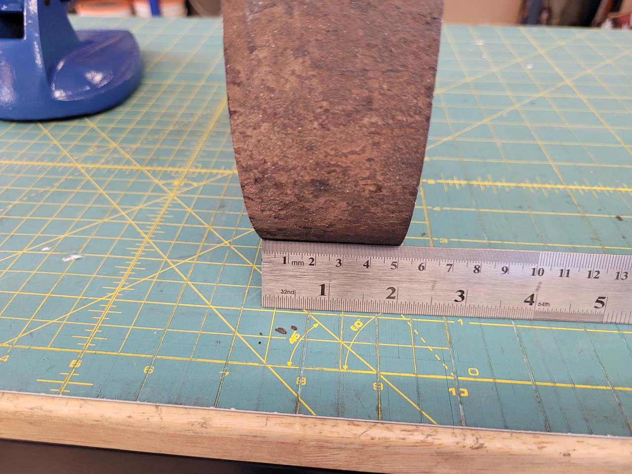
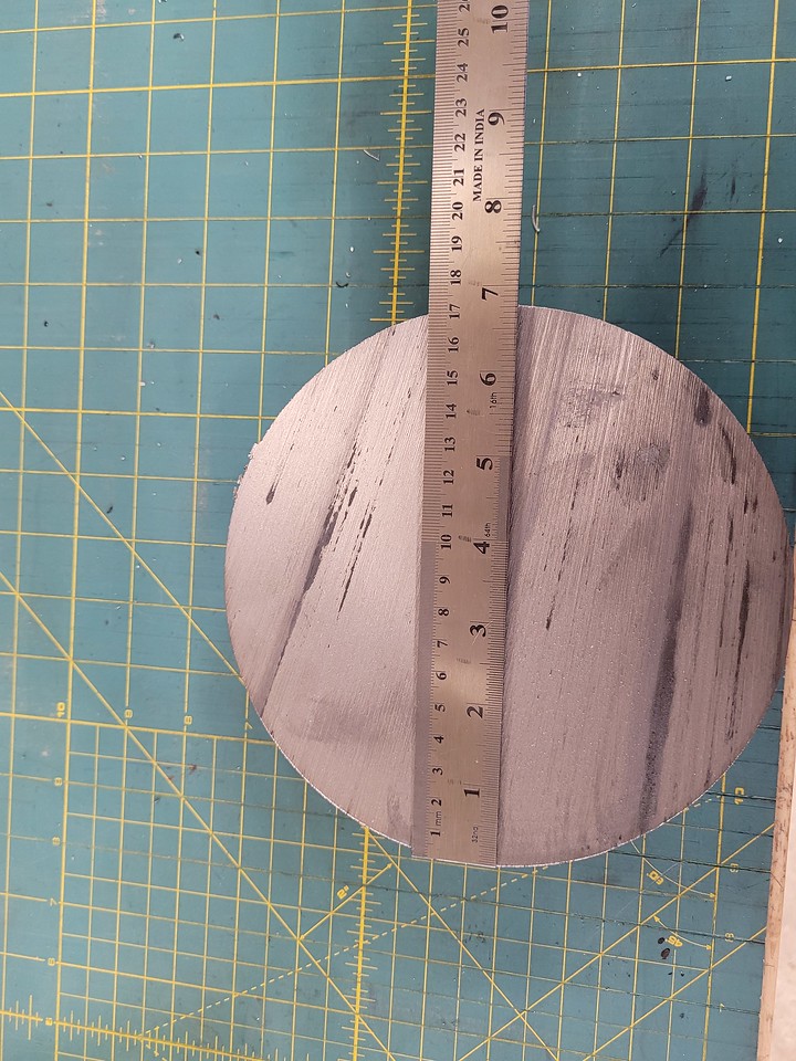
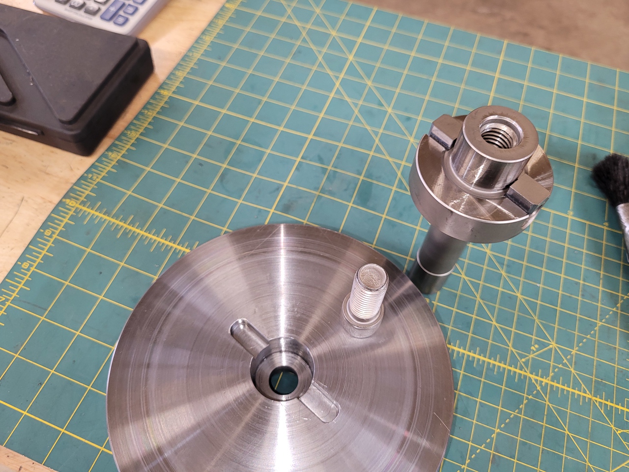
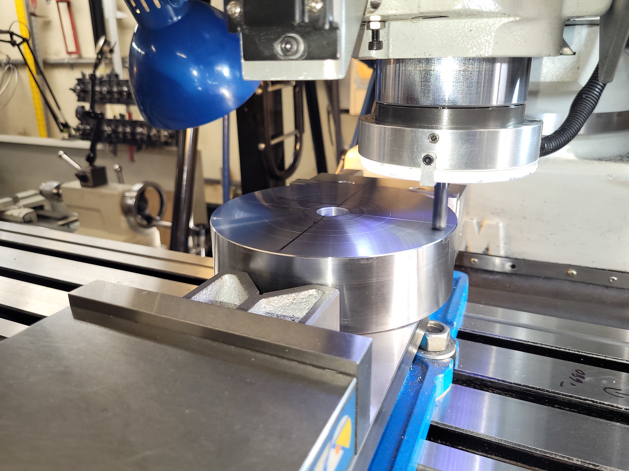
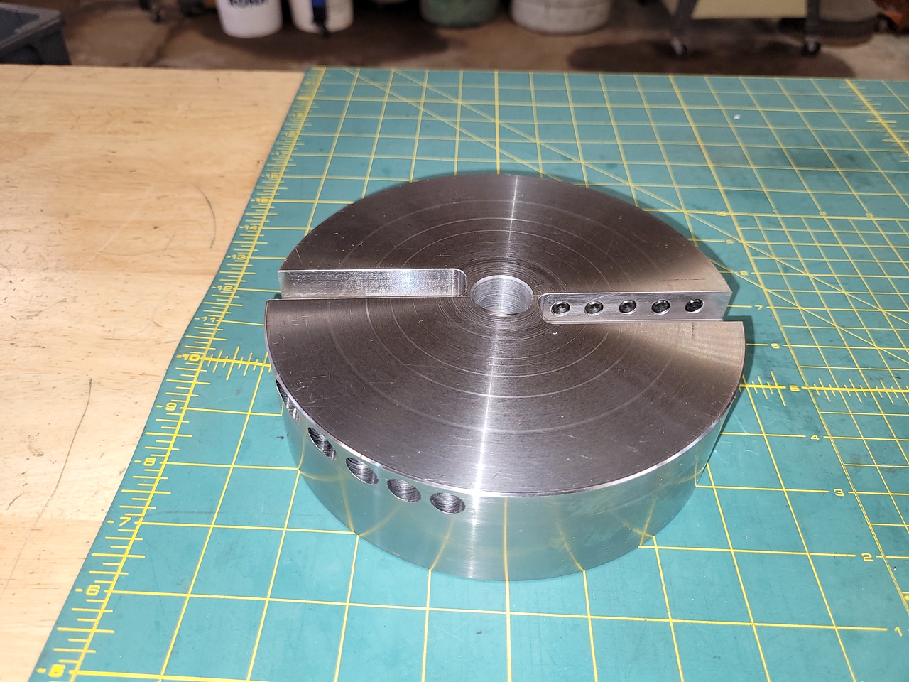
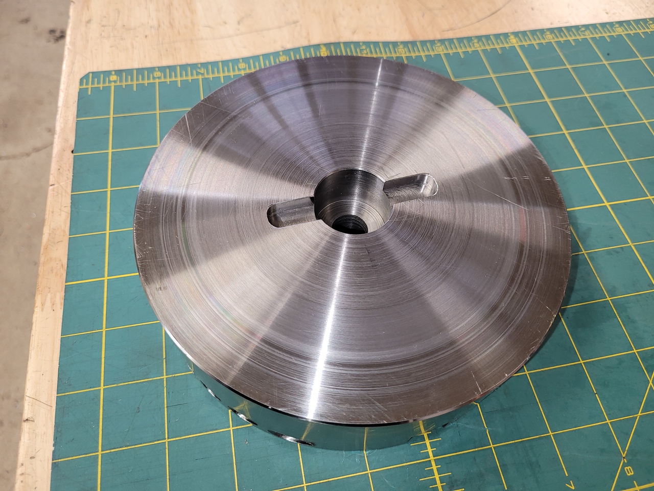
When I’ve tried to use it at larger diameters it has proved to be not rigid enough and starts to chatter and produce and poor finish. I have recently seen a few large diameter flywheel style type flycutters on youtube and ebay that got me interested in making one myself. None of the info I found gave me a feeling that one design was better than another or that 1 insert cutter type was preferred. I decided to build one that can use any style insert that I can make or buy a holder to fit. I bought a 1.25” R8 facemill holder on amazon and used a 2” thick slice of 6.75” 4140 material from the log I got several years ago.


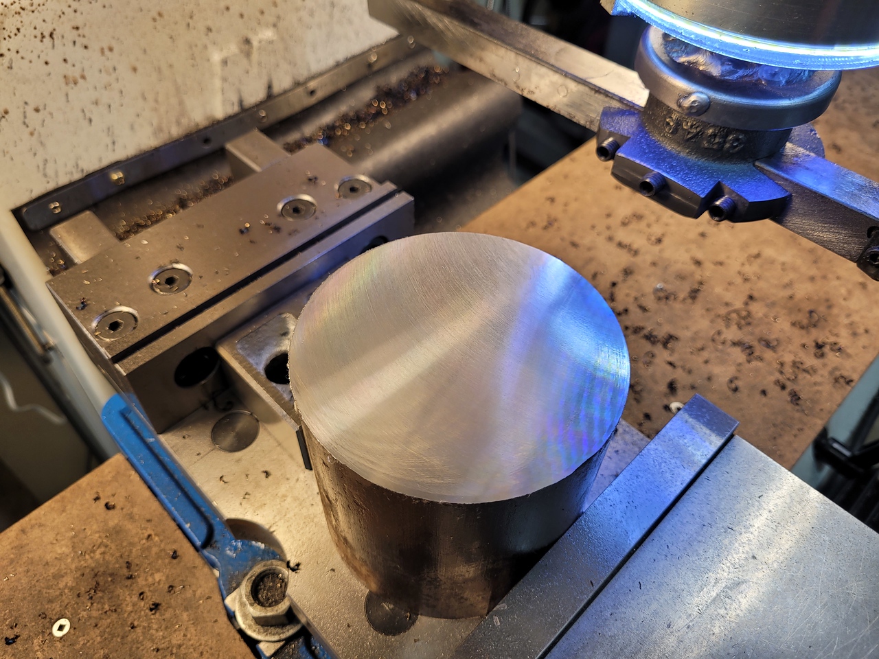
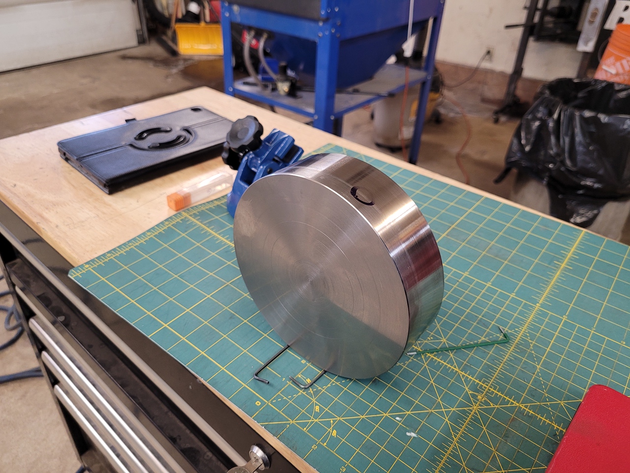
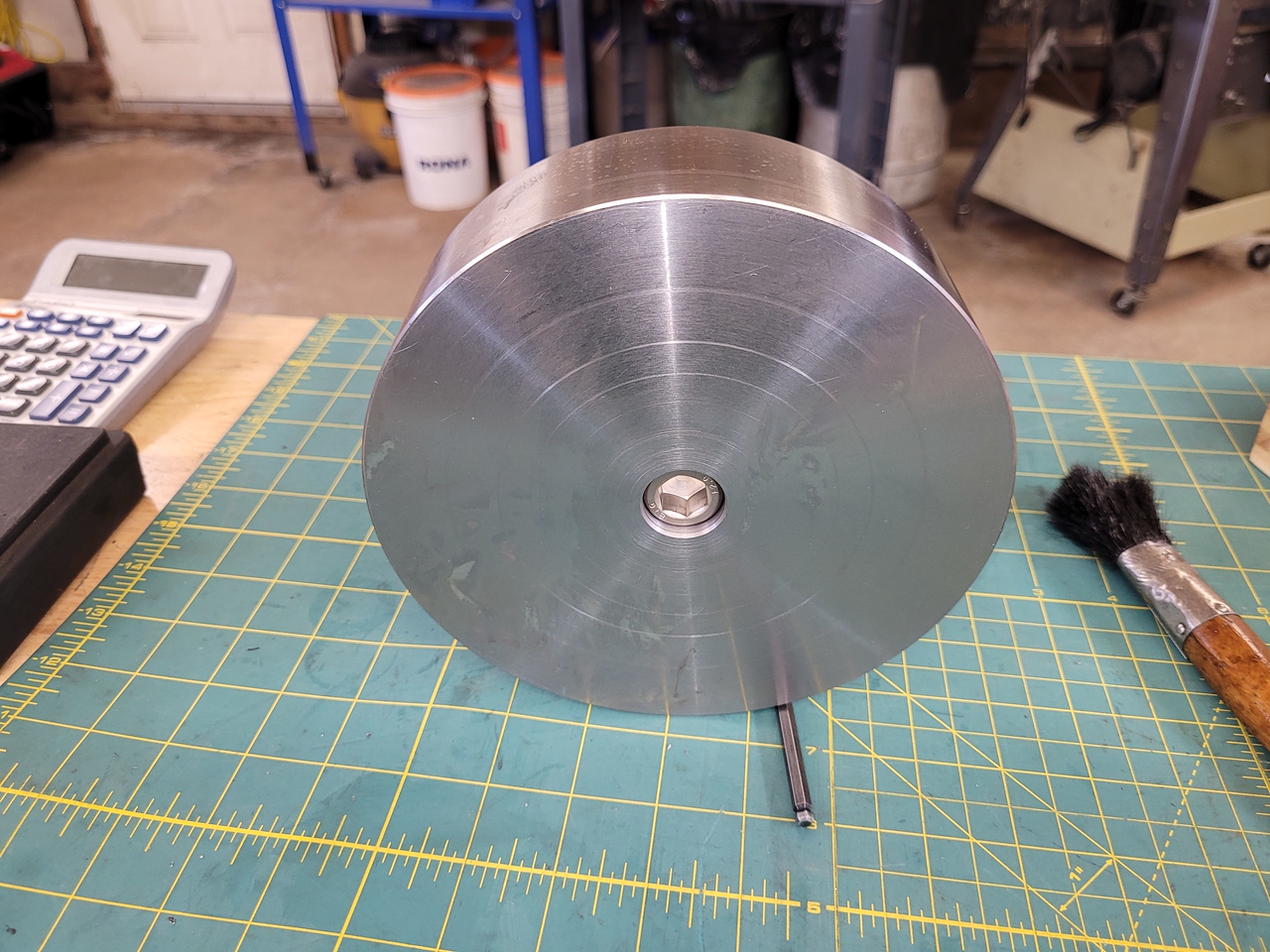
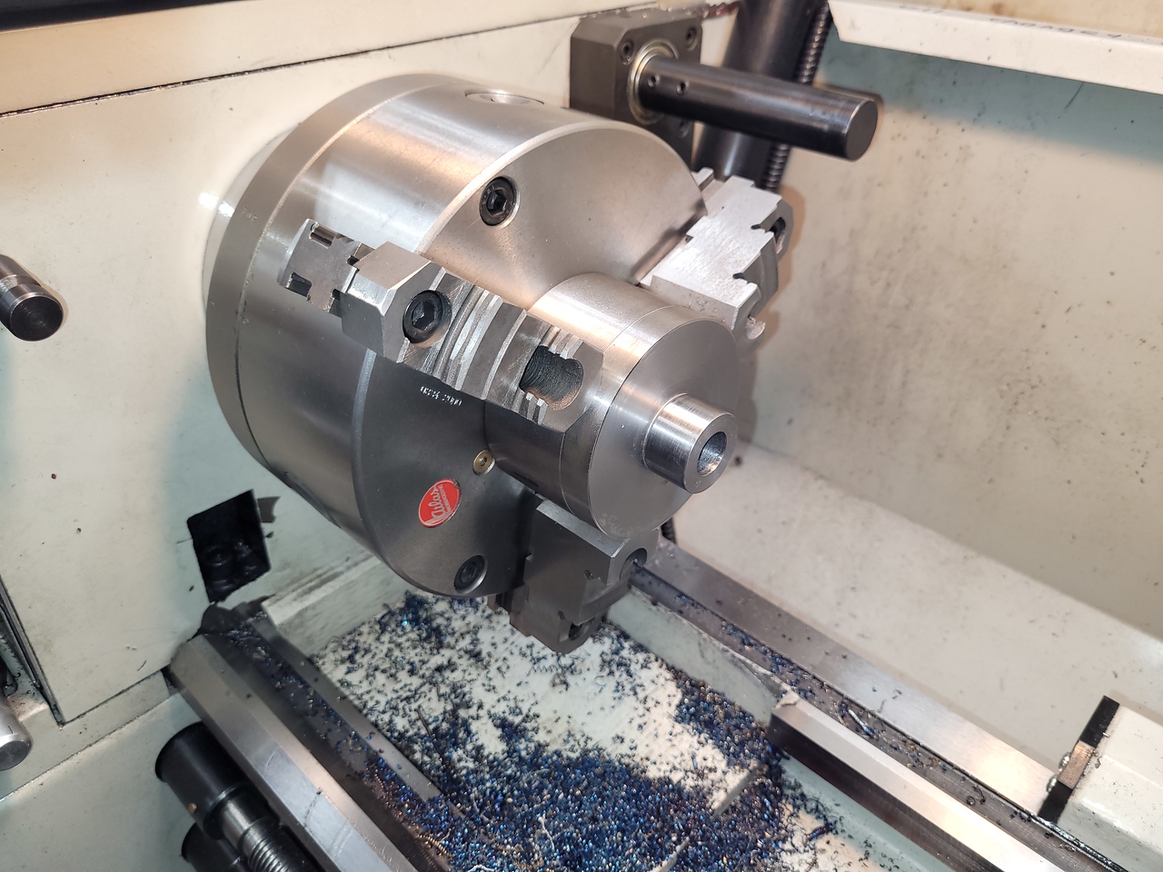
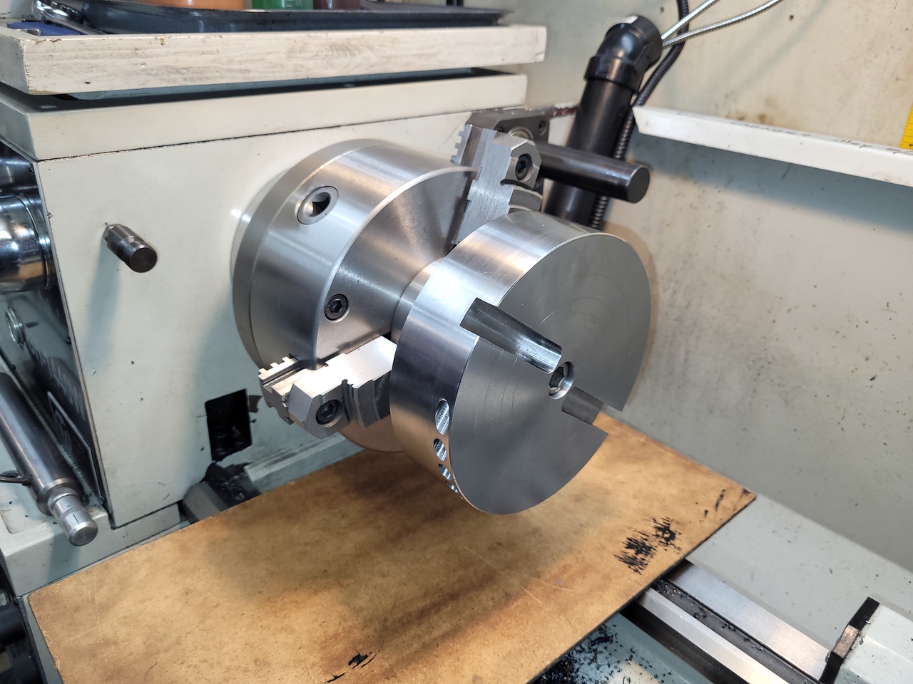
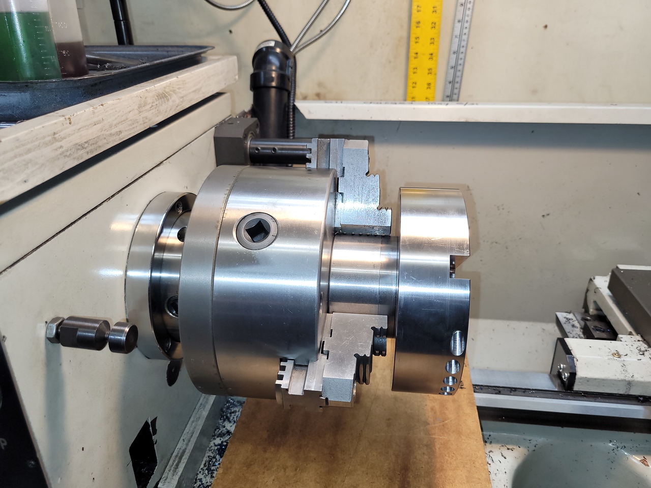
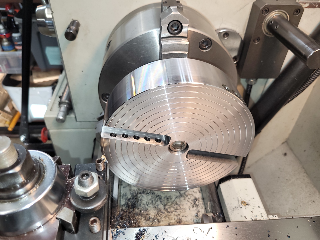
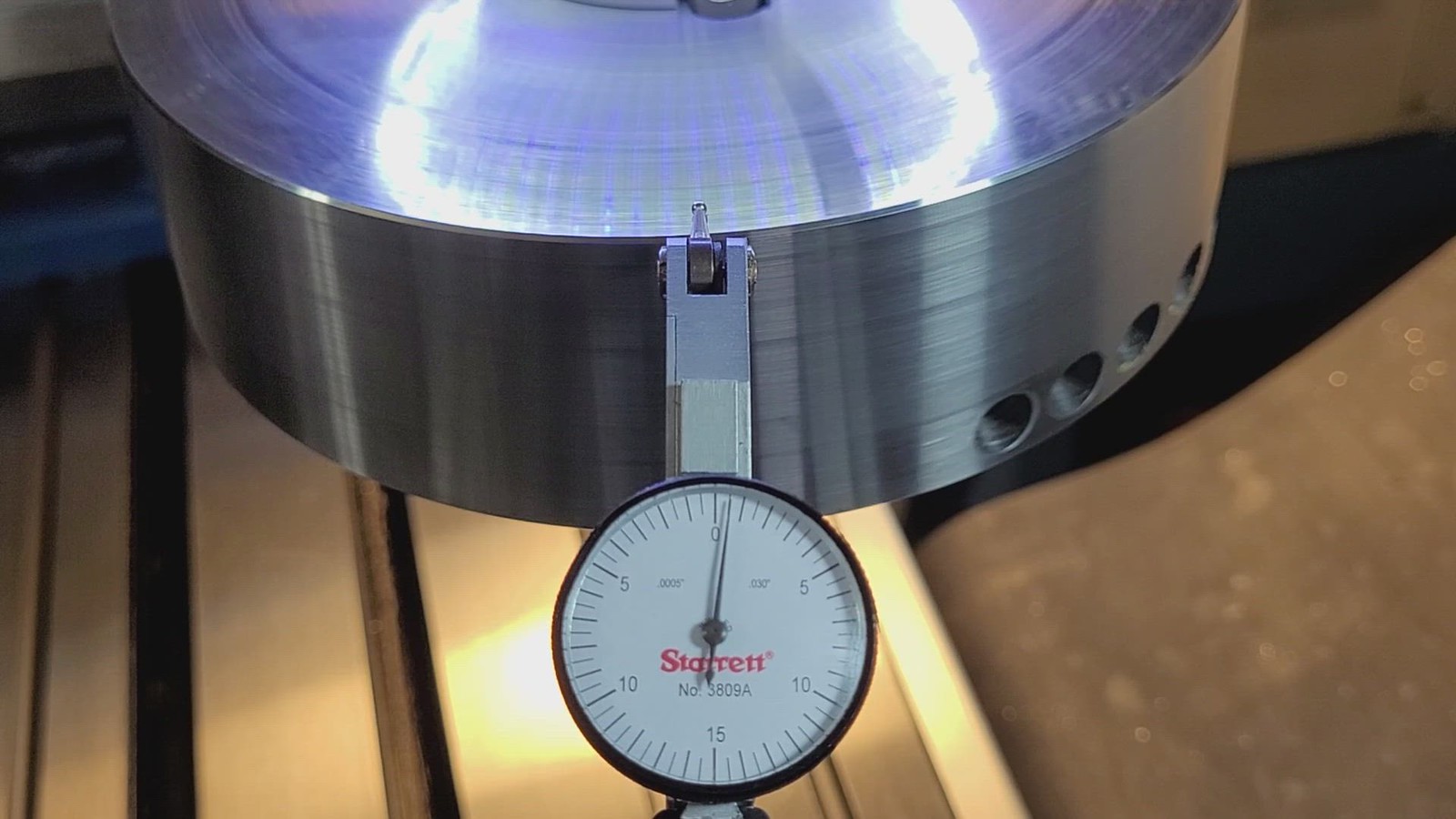
I trued it up in a 4 jaw chuck on the lathe, to be finish machined later.


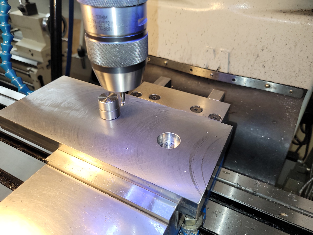
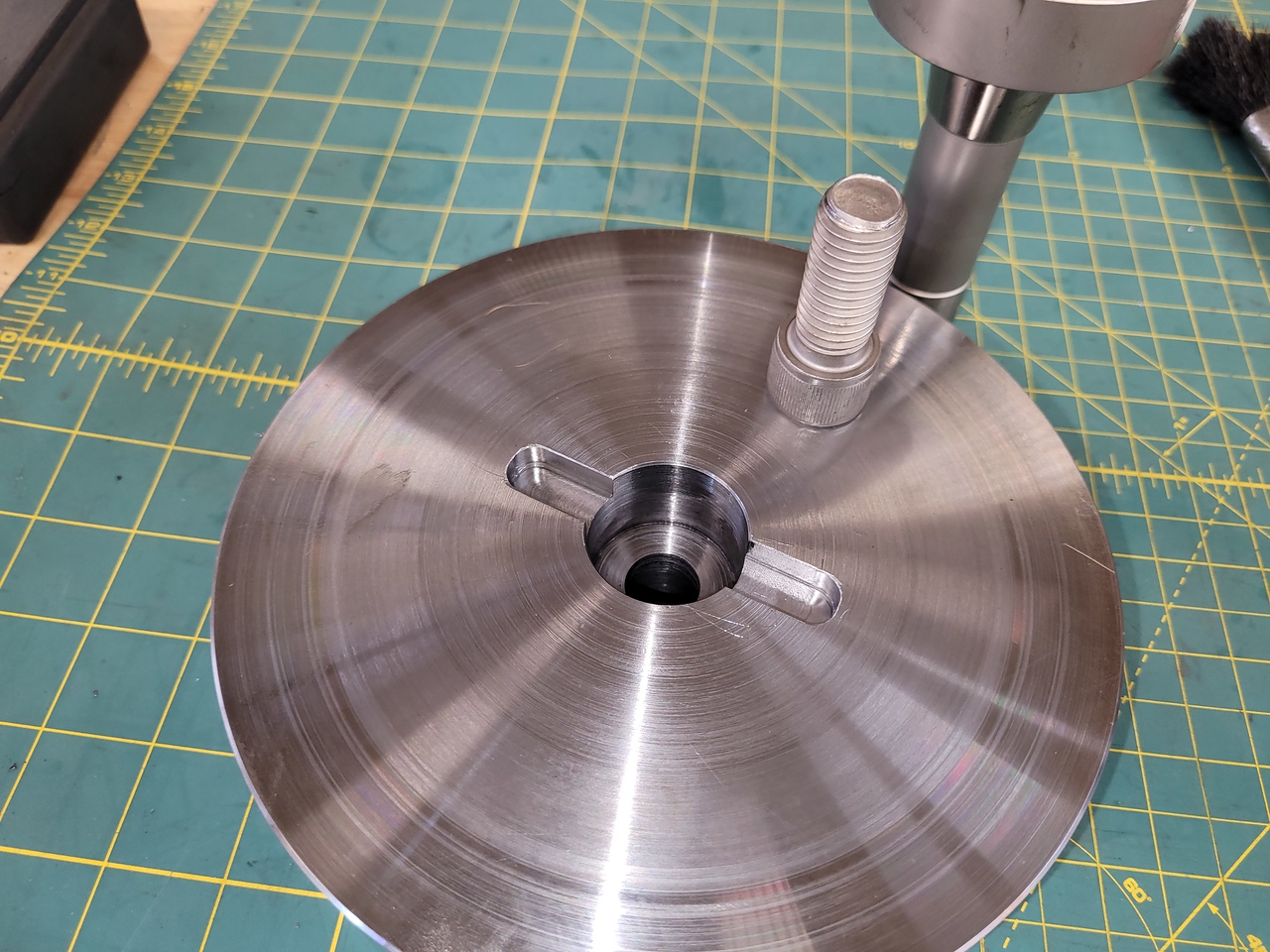
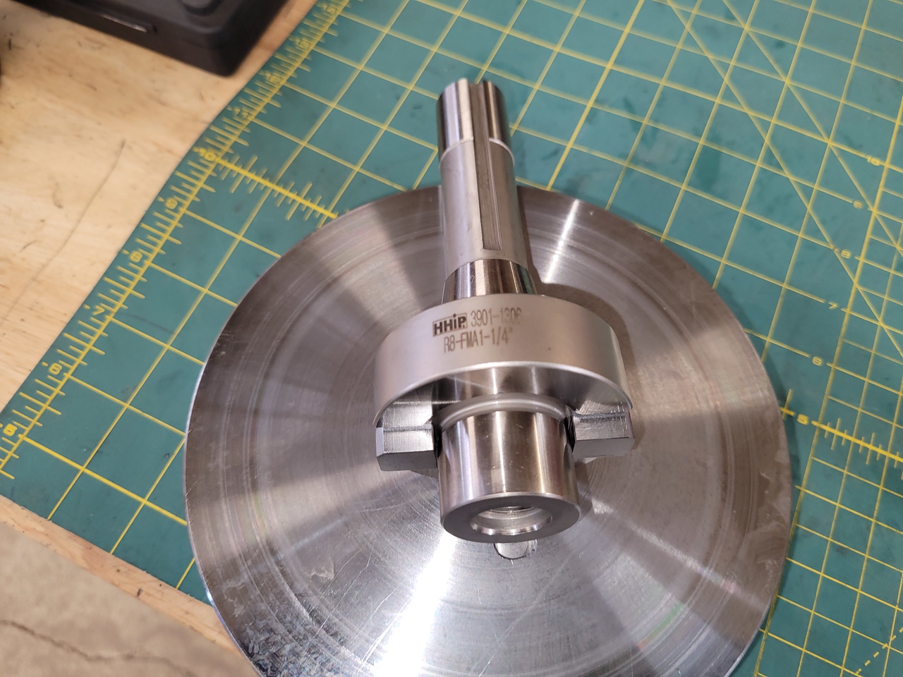
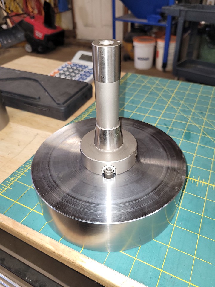
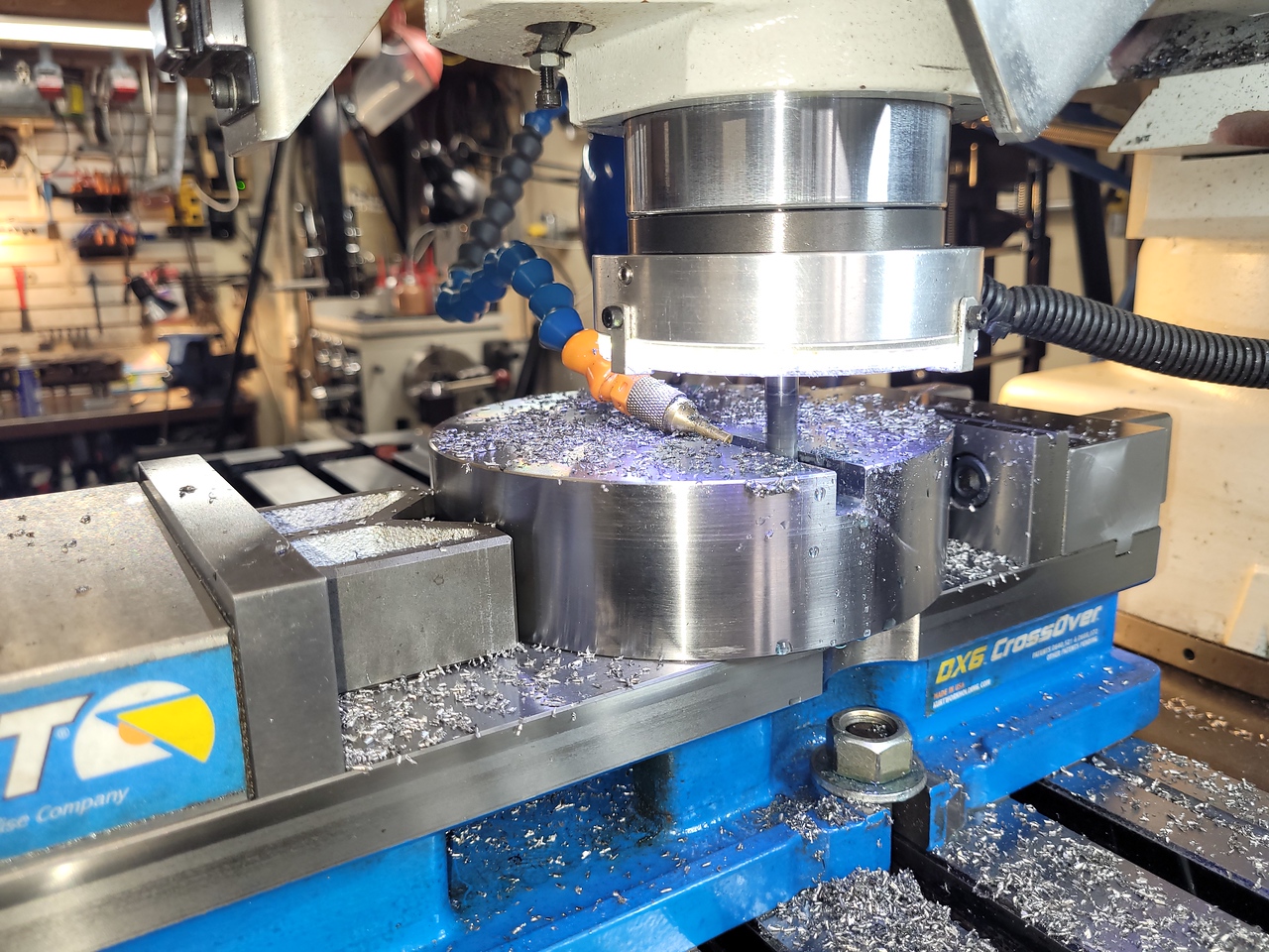
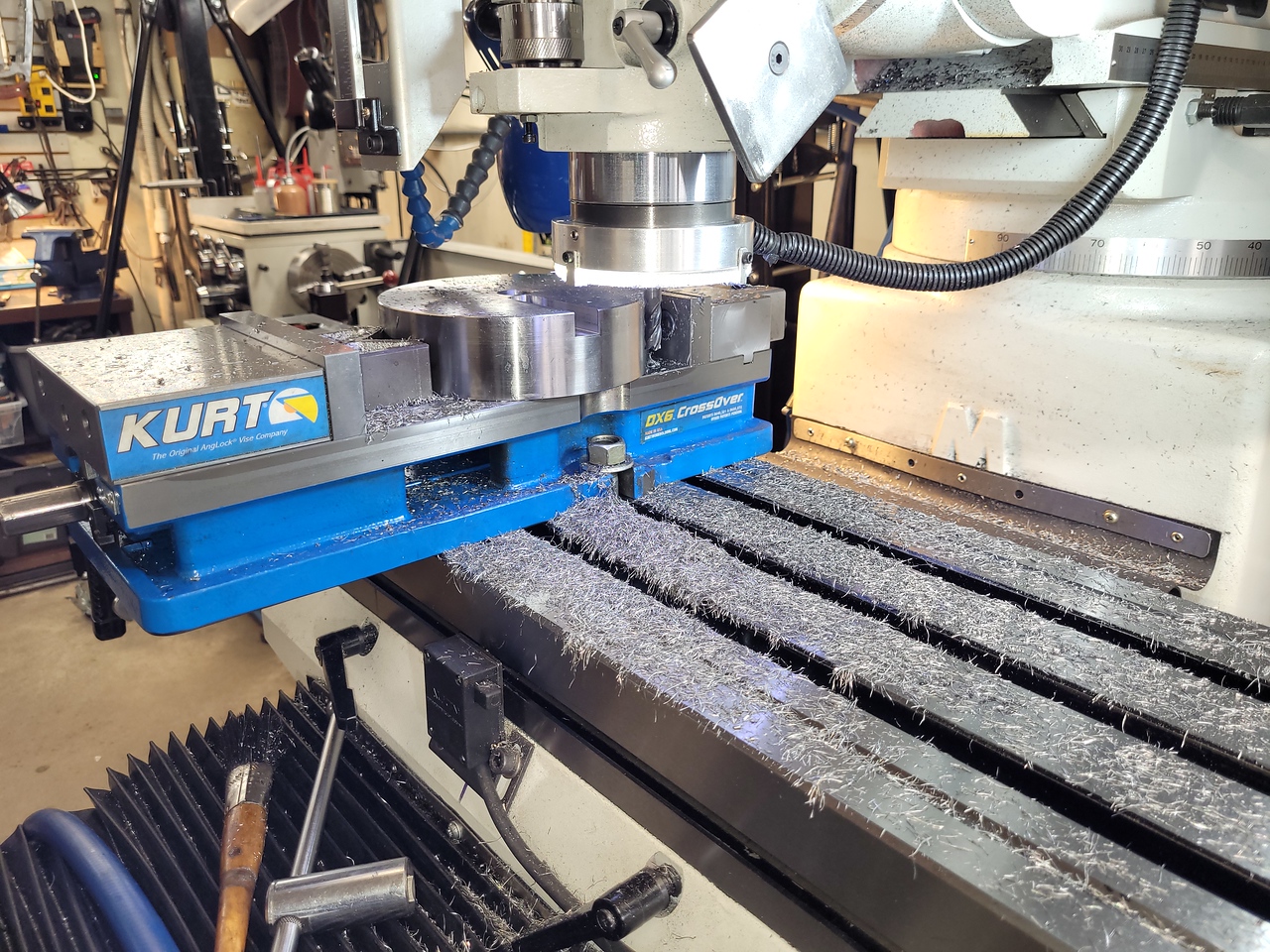
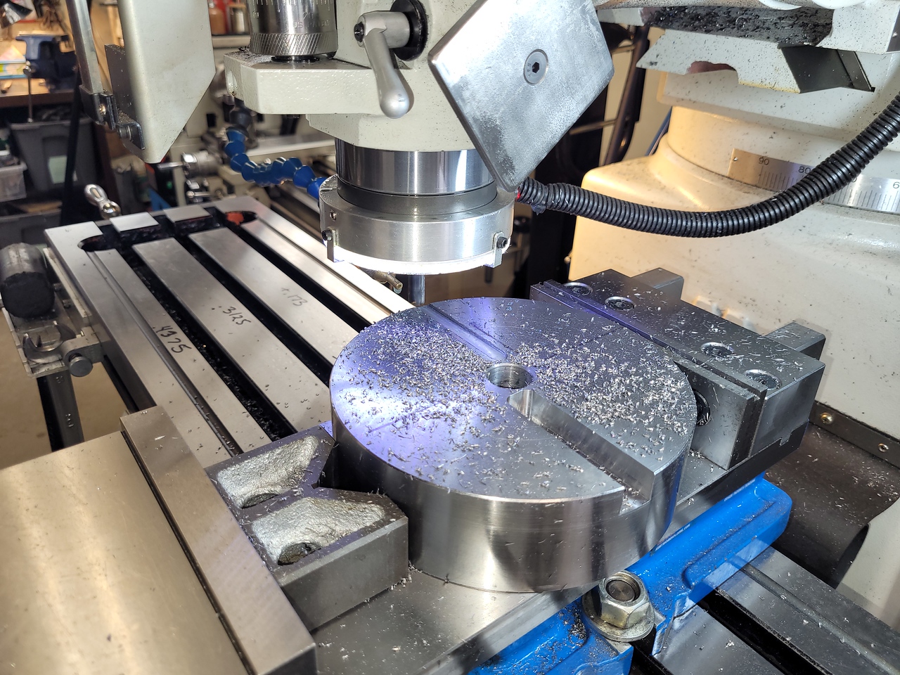
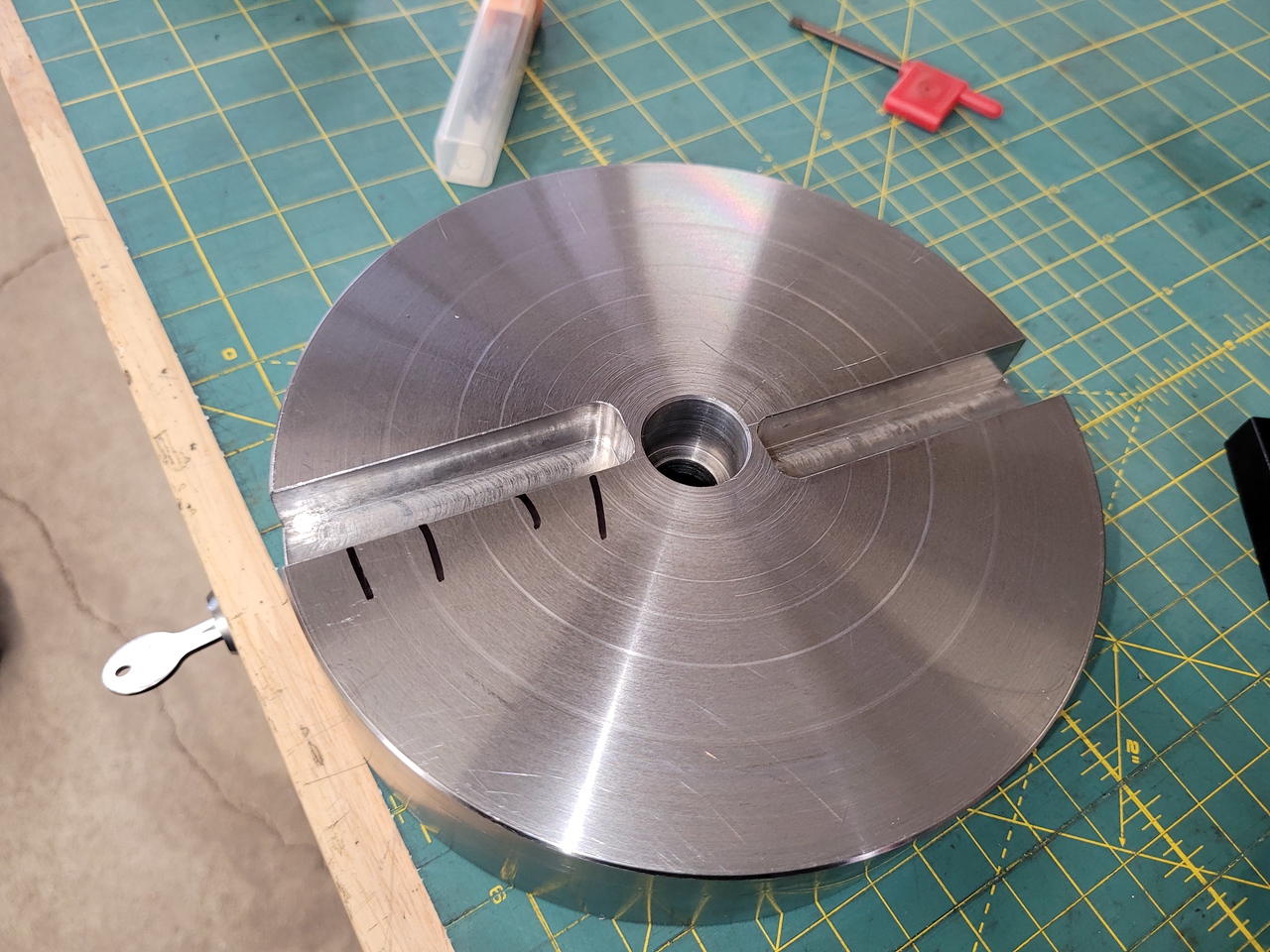
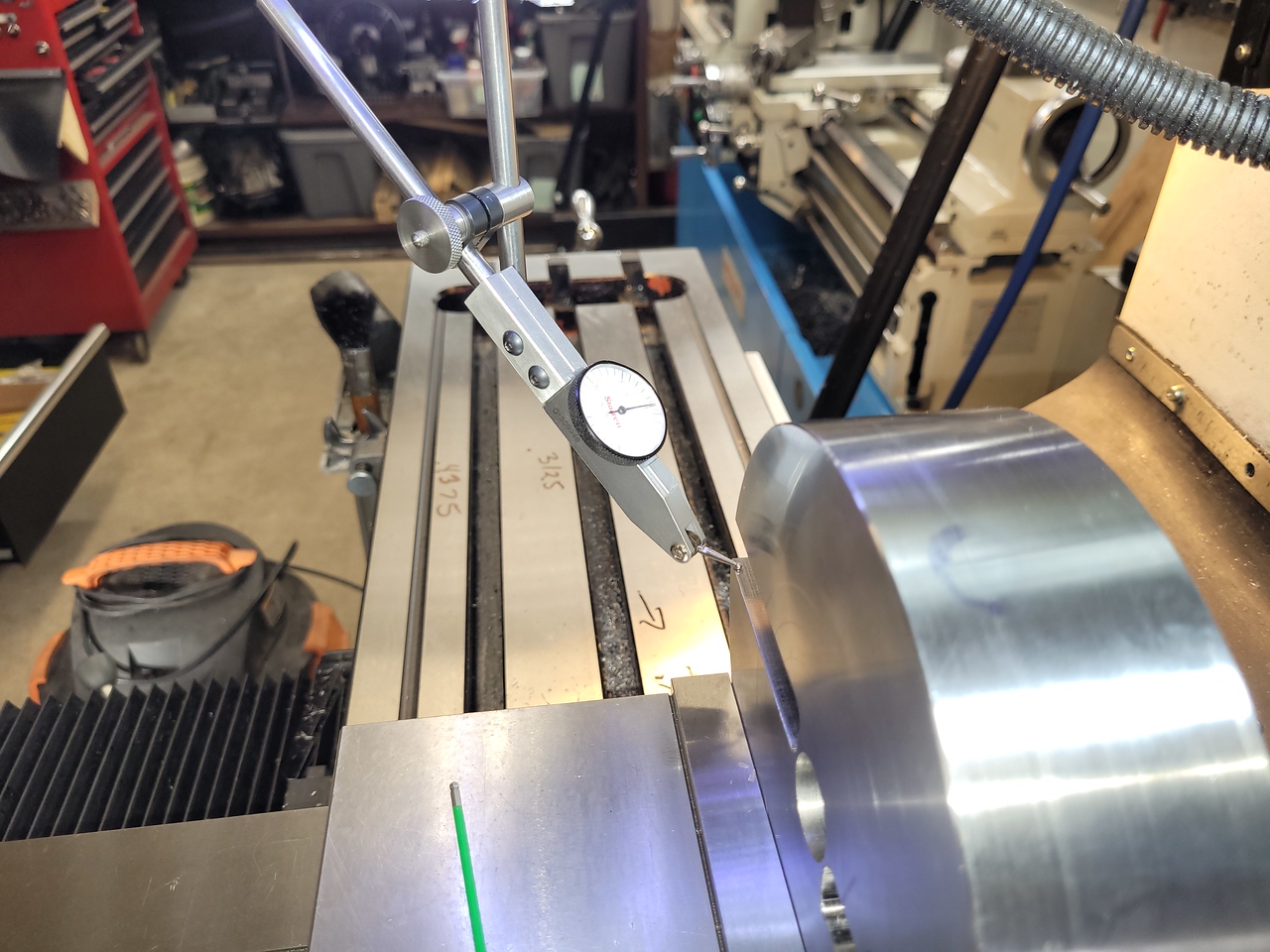
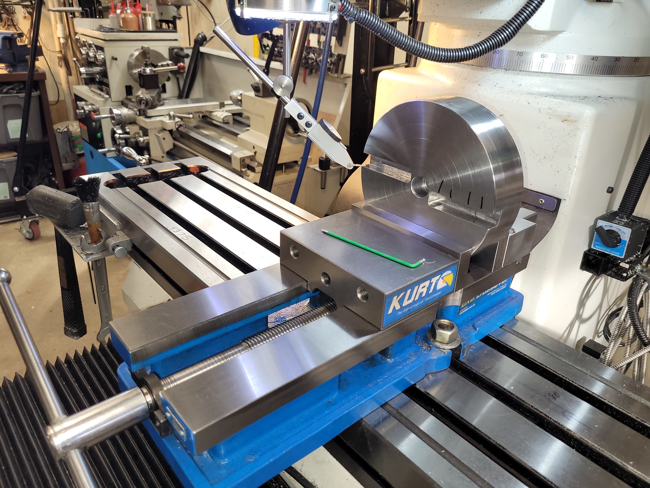
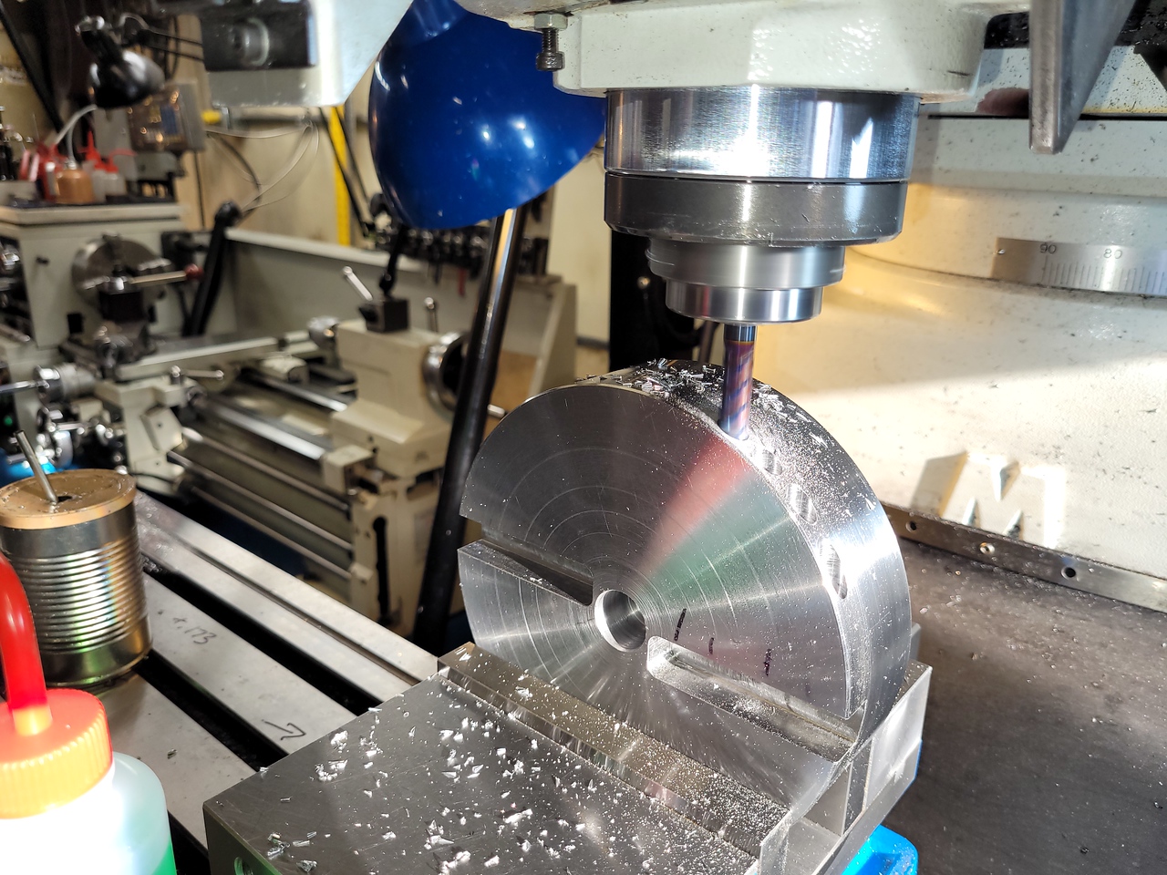
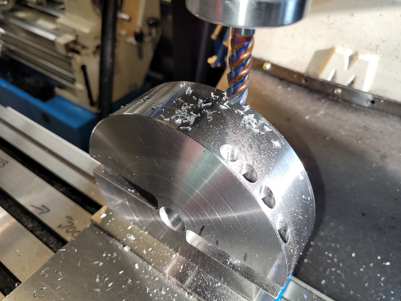
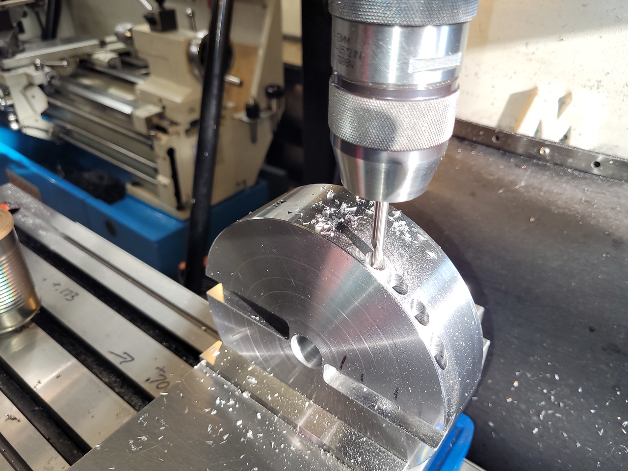
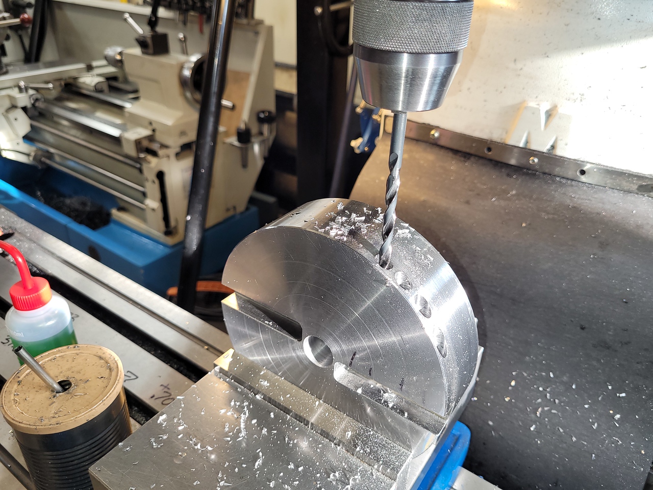
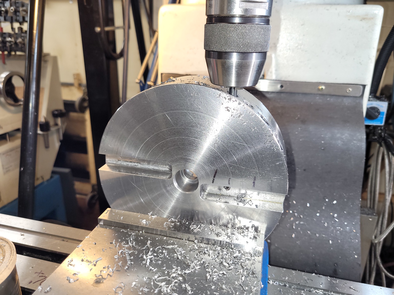
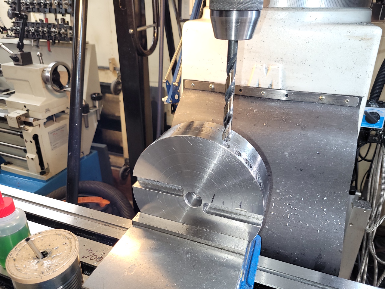
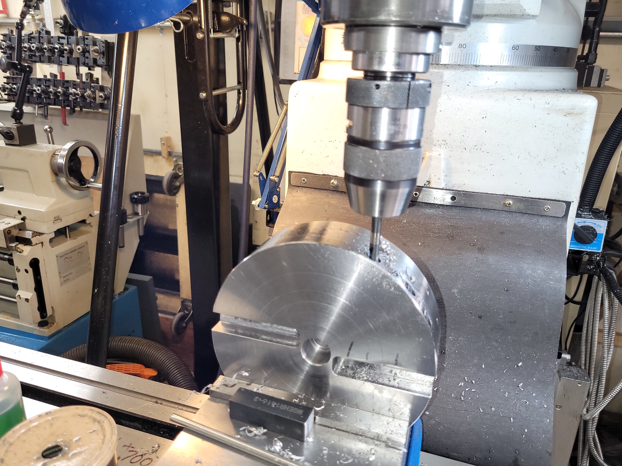
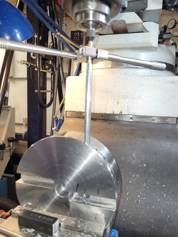
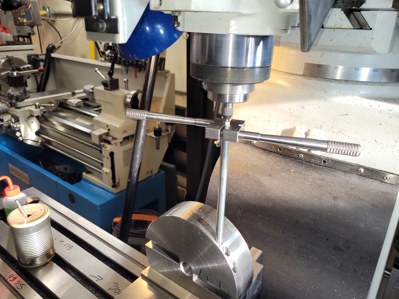
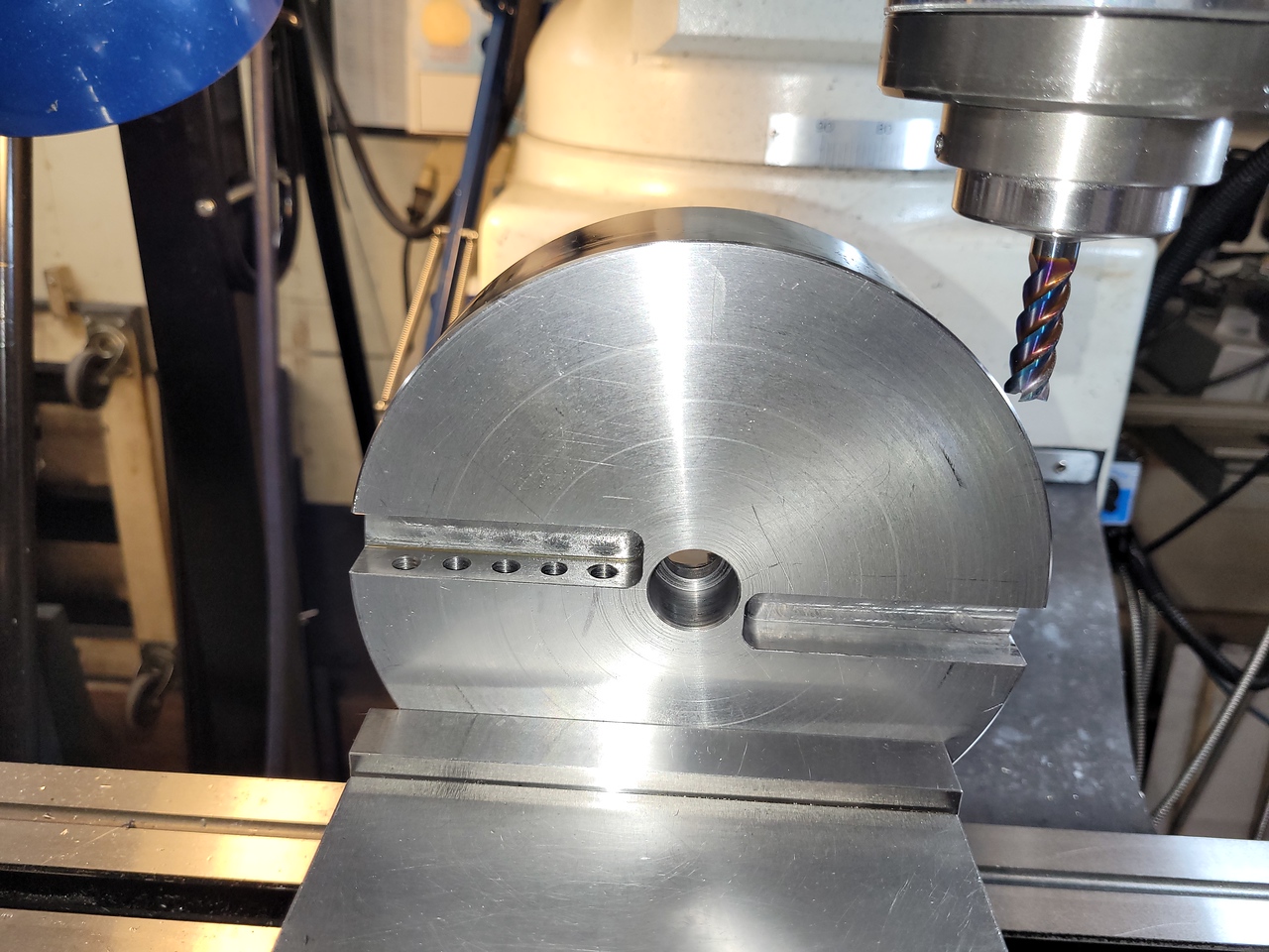
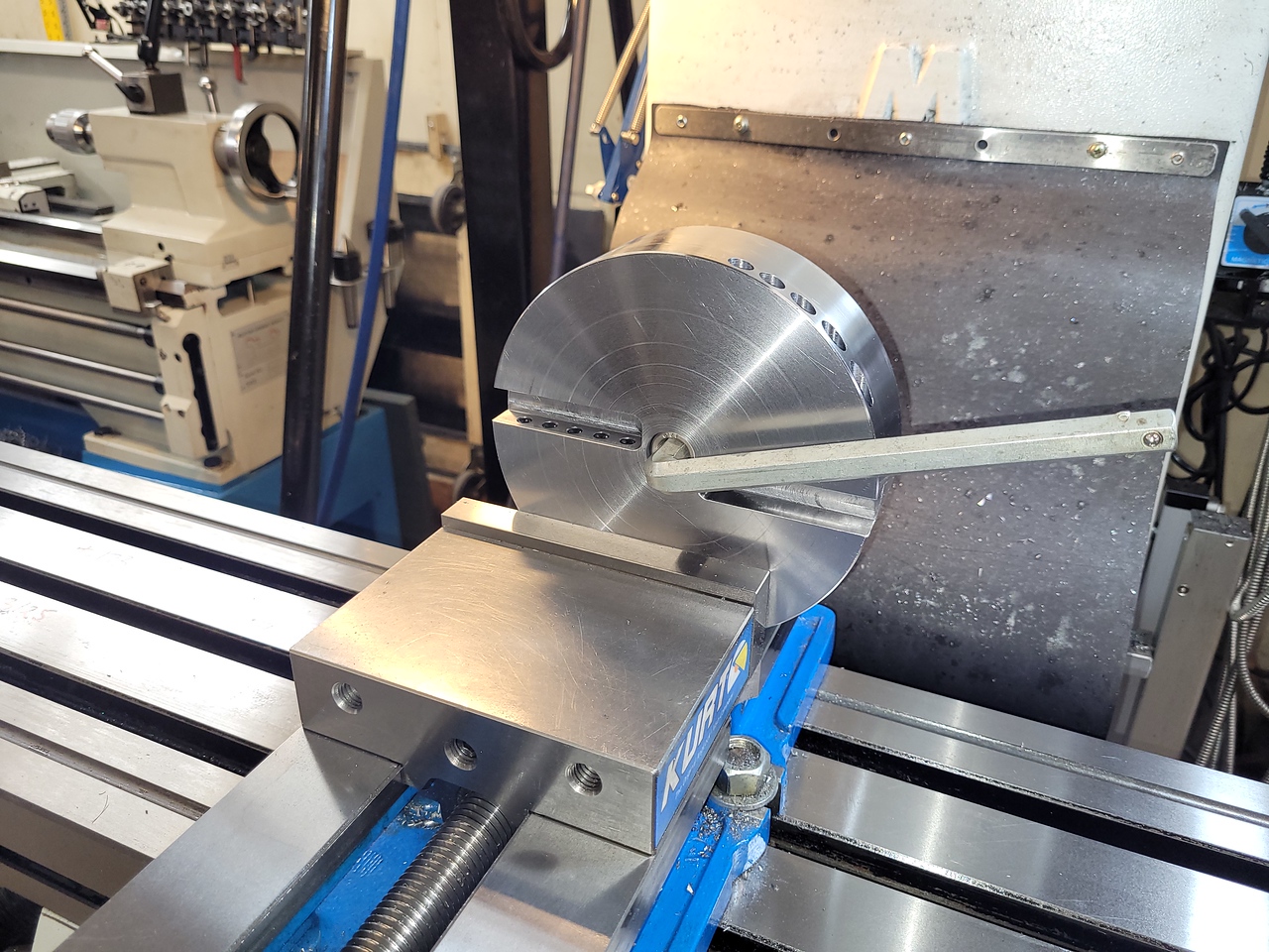
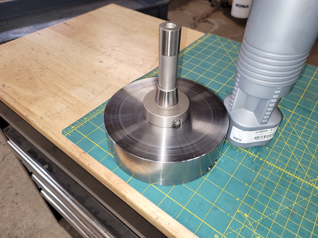
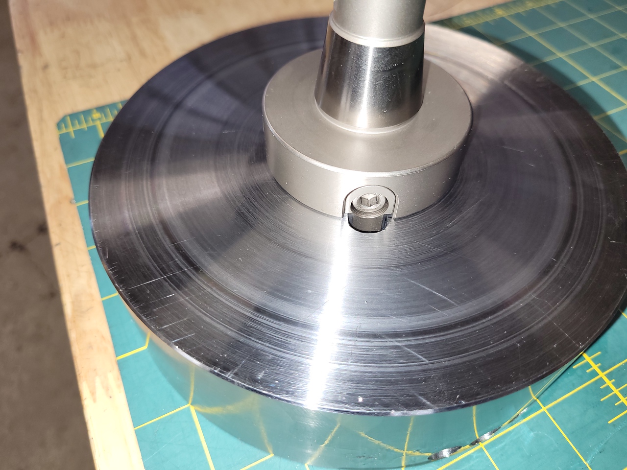
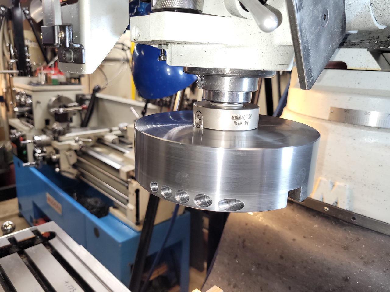
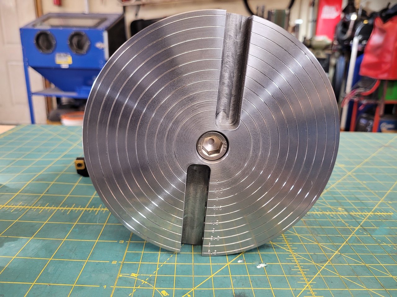
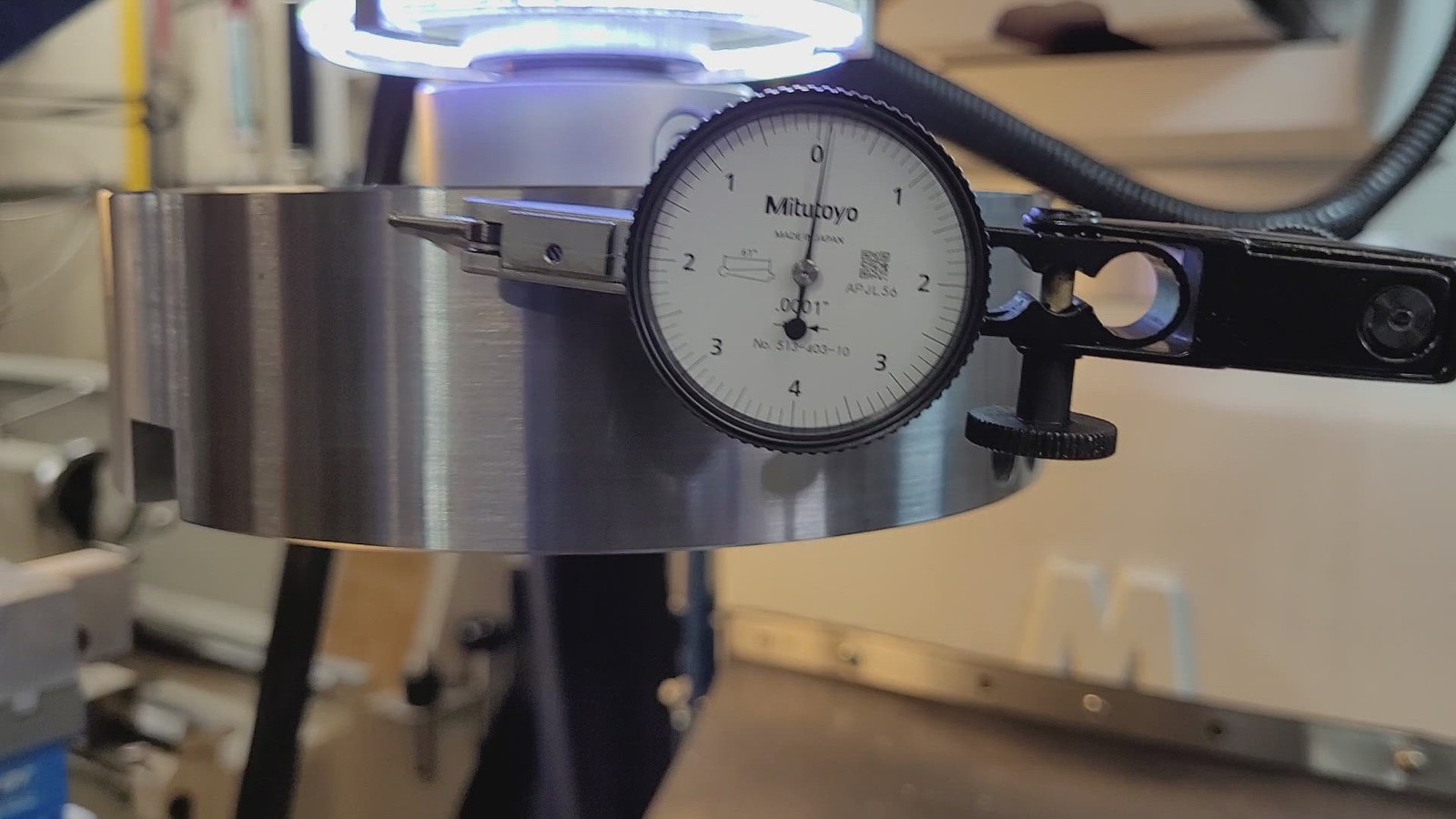
First I machined the 1.25” hole and the pockets for the keys on the face mill holder. I found that the 2 keys were different thickness so I machined them both to 7/16” wide and milled the pockets for a tight sliding fit. The round hole is a .0001” inference fit onto the R8 holder and can be installed or removed with a few taps with a dead blow hammer.


To be continued.
 
Last edited:

John Conroy

member
Premium Member
Then I flipped it over and milled the 2 slots to hold the cutter and counterweight. I used a 3/8" four flute carbide end mill with mist coolant cutting .100 depth on each pass at 1600 rpm. The slots are .630" wide by .550" deep and 3" long. I offset the slots so the cutting edge is on center to be sure the correct cutter geometry is maintained.


John Conroy

member
Premium Member
I plan on using left hand insert tools so the spindle can turn in the normal forward direction and send the chips toward the rear when traversing right to left as I normally do. Not knowing exactly what type of insert tool may be used in the future I wanted to have five M8 set screws spaced .5" apart in each slot the make it as adaptable as possible for varying diameters and tool types. I set the disc on edge in the vise and indicated and adjusted it until the slots were level with the table.


I could not find a M8 pulley tap or extended tap so I used a KBC house brand taper tap. I bored a hole in a length of 10mm drill rod for a light press fit onto the tap and pressed the them together with some red Loctite. That proved to be not strong enough so I tig welded the tap in place. I milled a square on the other end of the drill rod for a tap wrench. I think the off gassing of the Loctite caused the problem I had getting a good weld puddle but it held together for all 10 holes.


The process for each hole was to start by making a flat hole pocket with a 10mm end mill.


Next a 1/4" spot drill to get the hole started on center.


Then drill all the way through to the slot with a new 1/4" drill bit.


Followed by a 10mm drill bit leaving .600" at the bottom of each hole for M8 thread for the set screws.


Next a letter H drill bit that is the tap drill size for M8.


And lastly the tap. Of course I had to flip it over to do the second set of holes. It was a long process getting all 10 holes done but it turned out perfectly.


Last edited:

John Conroy

member
Premium Member
With the slots and screw holes done I cleaned up and assembled the parts and installed it in the mill to check the results.


I checked the runout and as I expect there was about .002" on the OD resulting from having to flip it in the chuck when I first machined one side at a time. It would probably be OK like that but it bugged me so I machined an arbor with a 1.25" hole to a snug fit and ran in some 5/8 NC threads for the mounting bolt. then without disturbing the arbor I mounted the disc on it and trued up the OD and front face.


I also machined grooves in the face spaced 1/4" apart and stamped them to indicated size based on location of the cutter,


Last edited:

John Conroy

member
Premium Member
I do quite a bit of work on small block Chevrolet cylinder heads so years ago I mad up a set of head stands that allow a head to be adjusted to level for gasket surface machining or measuring.

The 4 studs fit into 4 bolt holes in the head and can be adjusted up or down with an Allen wrench from the top.


This head is a scrap piece used for this trial. The video shows it has a .005" low spot in the center.

Link to video


I installed an insert tool in one slot and a piece of 5/8" square for a counter weight in the other. With this much weight I made sure to keep the spindle fully raised and made a .002" deep cut at 350 RPM and a very slow feed rate. The produce a mirror finish but did not fully clean up the hollow. I made a second.004" pass at the same rpm and feed rate. this completely cleaned up the head with a very nice finish. I shot a video of 1 pass. It is long and boring but go ahead and watch if you are bored.

 
Last edited:

Proxule

Ultra Member
Very nice project and write up John. Slick design and execution. It seems to work well.
I liked the video !
Those rings for determining stickout are clever !

Thanks for posting !

Curious is there a reason you choose smugmug ?
 

John Conroy

member
Premium Member
Thanks very much guys! We'll talk about Smugmug when we meet later this week, it's a long story.

Some points of interest regarding flycutter use. If your mill head is trammed normally the cutter will always cut on both sides of the spindle. If you set the depth of cut a .005" for example it will cut the .005" the first time the cutter passes over the part and will just rub on the second cut that is behind the spindle based on direction of feed. This rubbing affects the finish and I don't really like the look of it. I watched a video on Youtube where the user trams his head off to one side .003" in 8" sweep. No more second cut and much better finish but I was concerned that the cutter will render a dished cut. I decided to try his method today and the result is a much nicer finish. I swept the across the surface with tenths indicator and there is a dish affect to the finish but it's only .0003" over the 8" width of the head so not a concern.
 

Susquatch

Ultra Member
Administrator
Moderator
Premium Member
Thanks very much guys! We'll talk about Smugmug when we meet later this week, it's a long story.

Some points of interest regarding flycutter use. If your mill head is trammed normally the cutter will always cut on both sides of the spindle. If you set the depth of cut a .005" for example it will cut the .005" the first time the cutter passes over the part and will just rub on the second cut that is behind the spindle based on direction of feed. This rubbing affects the finish and I don't really like the look of it. I watched a video on Youtube where the user trams his head off to one side .003" in 8" sweep. No more second cut and much better finish but I was concerned that the cutter will render a dished cut. I decided to try his method today and the result is a much nicer finish. I swept the across the surface with tenths indicator and there is a dish affect to the finish but it's only .0003" over the 8" width of the head so not a concern.

I have always wondered about this but never tested it. Thanks for doing it and especially for letting us all know.

8" fly cutter eh! Wow! At 3 inches, my biggest is less than half of that!
 

PeterT

Ultra Member
Premium Member
Nice. That is a healthy cutting tool! What is your procedure to set the cutting tool edge relative to horizontal datum surface when the cutter shanks get mounted?

I've also read about different fly cut approaches & opinions. Some say its in the dynamic balance, some say in the head mass, some say the chunkier the shank the better, some say do away with the shank & put inserts directly on the body... Then you have different machines & rigidity. I guess if you have the finish now, you did it right! LOL

I like the surface finish of my face mill but its only 2". It has that slight 'back swipe' finish you were mentioning. My tram is about as accurate as I can get but I still see Zebra stripes between the extremity of overlap even if I traverse in same direction (full width cuts). Its really hard to feel anything with a fingernail. Usually 800# paper makes everything go away so I know I must be close. Not surface plate close of course. It has 4 inserts. One day I got wondering how the insert edges might vary vs datum surface between the 4 inserts. I set up my tenths DTI in a vise & rotated accross the ball. I would have bet a coffee they might be engineered to be depth staggered between inserts. Maybe 0.0002" I dunno. But my indicator said within a tenth or. I removed them, put new ones on, similar measurement value, but random inserts. Which tells me they aimed for the 'the same' but this is how it turned out given pocket tolerance + insert tolerance. Maybe that's just my model & others are different.
 

John Conroy

member
Premium Member
My feeling is that my smaller flycutter has too much flex so the extra leverage the tool has causes lifting and chatter. So I think rigidity and sheer mass make a huge difference. I have also read that insert geometry make a difference. That's why I chose a 5/8" slot, so I can try different insert styles. Some say large radius, some say small. Some say negative rake others say positive. I think rake angle is important based on how rigid the tool is. My thought is the a negative insert tends to push the tool away from the work while a positive rake tends to such the tool in. I have no idea which would be better with a less rigid tool. I plan to experiment with this stuff. I modified the dcmt insert holder I'm using now by milling a 3 degree angle on the top of it to give the insert some extra clearance back from the tip. The first edge of the insert did not survive the .004" cut but seems fine at .002". I also ran the rpm up to 500 for a short time on that first insert corner so that may have killed it. I see some guys saying to run a 8" flycutter at 650 rpm. I think the sfm would be excessive plus the chips would be pretty speedy. It took me a couple of hours to clean up the cast iron chips from that head, they fly a long way even at 350 rpm.
 

PeterT

Ultra Member
Premium Member
@John Conroy you have slightly different fly cutter tool, but my Paul X YouTube grazing made me think of you. I like the principle of his adjusters. He can semi tighten the main toolholder retention bolts, then micro-tweak any datum discrepancy of the tool/insert combination by rotating cutting edges over a DTI ball or whatever. A secondary benefit is it should help prevent the cutter shank from backing up the slot like maybe during interrupted cutting because the set screws are coming in laterally from the side. You have much longer, more rigid bars within horizontal slots. It obviously ran great in the videos. I wasn't sure if you were shimming or the tool shanks or they just stay put. Anyways, an idea for future projects. (Most of the video is of the jig, pic was grabbed as below)

KTM 530 exc - Leaning Cylinder Head - How To Attach It ?​


1677392087734.png
1677392993769.png
 

John Conroy

member
Premium Member
I watch his videos all the time, very talented guy! I wanted a single cutter like a traditional flycutter. The second slot is just for a balancing counter weight. I don't want the set-up hassle of a multi cutter tool, his is more like a face mill than a flycutter I think. The slotted design allows me to adjust the diameter of the cutting circle from about 5" to about 9". So rar I have made 3 cutters to test which gives the best finish. On 2 of them I machined a 3 degree angle on the holder so the cutter is the lowest part but obviously wasn't need on the round insert but on the ccmt provides a little tip clearance. The apkt ins3rt has tip clearance built in.

20230202_121130.jpg


20230202_121143.jpg
The surface finish is really nice with the single cutter, hard to get a good picture. I'll have to try some different lighting and angles to get better pics. This vid of checking the flatness shows to finish pretty well.

https://johnconroy.smugmug.com/Flycutter/n-GPB7pL/i-mBbd3QS


20230202_104435.jpg

20230202_103741.jpg
 
Last edited:

little ol' e

Jus' a hobby guy
My feeling is that my smaller flycutter has too much flex so the extra leverage the tool has causes lifting and chatter. So I think rigidity and sheer mass make a huge difference. I have also read that insert geometry make a difference.--
----------------------------------------------------------------------------------------------------------------------------------------------
How much does it weigh @John Conroy.
How did the TIR indicate when installed in the spindle?
Have you considered coating or just leaving the machined 4140 exposed?
That's a nice 10mm finishing endmill..
Nice work !
 
Last edited:

John Conroy

member
Premium Member
My feeling is that my smaller flycutter has too much flex so the extra leverage the tool has causes lifting and chatter. So I think rigidity and sheer mass make a huge difference. I have also read that insert geometry make a difference.--
----------------------------------------------------------------------------------------------------------------------------------------------
How much does it weigh @John Conroy.
How did the TIR indicate when installed in the spindle?
Have you considered coating or just leaving the machined 4140 exposed?
That's a nice 10mm finishing endmill..
Nice work !
Thanks Eric, it weighs just over 20 lbs with the arbor. I took 2 short vids of runout measurements, .0009" radial and .0005" axial run out.


I don't think i'll do any coating, I just spray everything down with fluid film when not in use.

I get those end mills on Banggood, cheap and good quality.


drillpro.png
 

little ol' e

Jus' a hobby guy
Thanks Eric, it weighs just over 20 lbs with the arbor. I took 2 short vids of runout measurements, .0009" radial and .0005" axial run out.


I don't think i'll do any coating, I just spray everything down with fluid film when not in use.

I get those end mills on Banggood, cheap and good quality.
A little over 20lbs, OK.
I noticed the chip color, load and formation. I noticed on this project you don't seem to be using coolant;)

My guess would be, you will be running lower than 350 RPM in time with different inserts when machining cylinder heads perhaps? Interrupted cuts are a bugger in those head castings.
Do you feel as thou the rotating weight mass could eventually do harm to your spindle, bearings or housing over time?

Fluid film has gotten expensive these days, being a car guy myself.
I use mine sparingly these days. I picked up a project Olds in 2021 on the cheap, and its still covered in fluid fill. Probably 1 of those projects that will be sitting long after I kick my clogs..

My brain is telling me, I've got to ask....
How much your taking from those Chev heads ? A compression boost ? Or just clean up for new head gaskets?
 
Last edited:

Stellrammer

Well-Known Member
Good work on that, I made a similar boring tool out of an old flywheel from a 2 Litre Triumph six., I doubt it would make a good fly cutter though, forces would work against it, a .010” DOC @.0035” feed isn’t much to contend with in a bore.
Mass and rigidity can’t be beat, size of taper and type of taper are influential. The difference between a 50 taper shrink holder and one that contacts both the flange and taper when drawn up is considerable. The ability to rough and finish while giving better tool life is apparent.
If you are going for finish, a sharp edge Milling insert with a wiper flat designated for low feed finishing will make life easier. Typically the smaller radius is on a turning insert the better the finish is going to be, but that is still a proponent of feed and depth. Ideally the radius should be buried to reduce chatter and render chip control. control the chip and you can control the finish in most materials.
You will rarely find turning inserts with a wiper flat, they don’t really work all that well in that their very nature can cause chatter if not set up correctly. You will not find an insert with a truly dead sharp edge, at the very least there is a rolled over edge from a “brush” hone that will be over a thou.
Most manufacturers will have inserts specifically for finishing, usually the ones for heat resistant alloys are edge prepped to be sharp and have wear resistant coatings. The sharper the edge the weaker it is though.
The problem with edge preps , especially in the ultra cheap offshore pressed ones, is inconsistency or just plainly poor quality control. If you are dealing with an insert that has an .008” edge prep/land , anything under an .008 feed is now negative rather than a positive rake, causing finish issues and chip control problems.
These are some of the reasons using a milling insert with a ground chip breaker is a better choice. The edge is far sharper and the radius truncated, giving not only the larger contact flat wiper but reducing cutting forces from the radius.
In short a larger radius turning insert is going to create a few issues. The rad is not likely to be buried and the edge prep is typically more negative, giving needed strength but creating more cutting forces, everything is always a compromise.
I don’t know what the state of the industry is right now as far as knowledgeable technical reps vs “sales” oriented personnel, as far as the tooling manufacturers and distributors.
It is worthwhile to culture a relationship with a rep that knows his stuff, if you have to tell someone what you need and how to get it or even what it is then you both might be disappointed.
Cheers Tim
 

PeterT

Ultra Member
Premium Member
That looks pretty darn nice from where I'm standing. Are heads like that cast iron?

Your flywheel haha FLYCUTTER is big & very symmetrically machined. I'm guessing its as close to perfectly balanced as practical. Once upon a time I drew up a regular flycutter in CAD, the kind with the bevel bottom & cutter sticking out the side & computed the resultant center of mass. It was off axis as expected, but the question becomes does that adversely affect finish (compared to the other cutting tool factors). If the spindle bearings contain the imbalance load I cant see it being a problem. If one had a big heavy + unbalanced + high RPM setup, that would be an issue. Like grinding wheels which are relatively light but high rpm.

1677445772609.png
 

Susquatch

Ultra Member
Administrator
Moderator
Premium Member
I don't think i'll do any coating, I just spray everything down with fluid film when not in use.

Fluid film has gotten expensive these days, being a car guy myself.
I use mine sparingly these days.

Fluid Film works. No doubt about it. But there are better products out there. Trouble is that they cost even more.

I look at it maybe a bit different. As a hobbiest, I don't really care much about wearing out my tools or getting the best economic value out of them, or optimizing their life, or or or. I just don't use them enough for any of that to really matter. I don't do production runs or high volume. Time is not money for me. In fact, quite the opposite. Taking as much time to make whatever I want is what I love to do. I am never happier than cranking the handles on my mill or my lathe making something simple and beautiful.

For the most part, my tools are just gunna sit on the shelf or in the drawer. However, I don't want them to rust away for lack of use or proper protection. So I don't mind spending a fair bundle on ways to protect my tools so the ones I have are still there when I need them.

For me, the horror of opening a drawer to discover an R8 Arbour covered in rust is a total nightmare and I'm willing to pay a fair bit to avoid that.

If you think Fluid Film is expensive, try WD40 Corrosion Inhibitor. So far it's my leading favorite but that story has yet to be told.
 
Top