• Spring 2024 meetup in Calgary - tentative date Saturday, April 20/2024. Other regions are also discussing meet ups. If you want one in your area get going on organizing it! discussion
  • We are having email/registration problems again. Diagnosis is underway. New users sorry if you are having trouble getting registered. We are exploring different options to get registered. Contact the forum via another member or on facebook if you're stuck. Update -> we think it is fixed. Let us know if not.
  • Spring meet up in Ontario, April 6/2024. NEW LOCATION See Post #31 Discussion NEW LOCATION

Over the top ball turning attachement

PeterT

Ultra Member
Premium Member
Setup wise, a useful accessory is a slotted angle plate. It gets mounted firmly to the table. Then the work gets clamped to a face. The added surface area + clamping force = increased security of drift & also rigidity. The cast iron imports can be reasonably accurate but they are heavy so beware shipping. Also the slot spacing needs to be checked vs your T-slots.

Another option is clamping stock to the table flat side down with some kind of offset riser or sacrificial board. MDF works reasonably well unless you need to a couple thou. Now you would mill 2 parallel sides say in X direction, dropping the end mill in whatever depth increments it can take. Then then take a very light finishing pass of only say 0.005". Put new clamps across & mill the 2 Y direction same way. This method gives you automatic squareness & possibly sets you up for the internal relief.

In both cases, tall + thick + steel + smaller machine is a tough combination so there are pros & cons to each. The more you can cut away with a saw the better. Also roughing end mills work well, nut just for hogging material on big boy machines. They put less stress on smaller mills. But they are not for finishing. That's why I like to have a rougher in same diamter as conventional end mill, saves on setup & calculations with just one tool change.
 

Attachments

  • 2019-01-05_19-23-25.jpg
    2019-01-05_19-23-25.jpg
    49.8 KB · Views: 0
  • SNAG-1-5-2019 0002.jpg
    SNAG-1-5-2019 0002.jpg
    6.2 KB · Views: 0

PeterT

Ultra Member
Premium Member
flat side down method
 

Attachments

  • IMG_5720_edited-1.jpg
    IMG_5720_edited-1.jpg
    52.1 KB · Views: 1
  • IMG_5722_edited-1.jpg
    IMG_5722_edited-1.jpg
    37.4 KB · Views: 1

YYCHM

(Craig)
Premium Member
X2

Also use a smaller diameter milling cutter (ie. 3/8” to 1/2” max) and employ step-over passes. That reduces the amount of power / rigidity required from the mill and works safer (albeit slower) for questionable set-ups (like stuff that sticks out a long way from its hold down).
Looks like you are trying to use about a 1”, two flute cutter. These require some serious power and rigidity. I rarely use anything bigger than a 3/4” endmill on my Bridgeport size milling machine in steel.


Now this is an interesting comment. A book I have states to use the biggest end mill available to do the job?

I was using a 1" 4 flute end mill.
 

RobinHood

Ultra Member
Premium Member
A book I have states to use the biggest end mill available to do the job?
I do agree with what your book states. It probably also assumes that you are able to clamp the work securely in a rigid manner and have the spindle power to turn the endmill at the proper feed and speed for optimum material removal and surface finish. If any one of these variables are not 100% (as often is the case in a hobby environment), it is time to come up with an alternate plan: take lighter cuts, use a smaller cutter to reduce the “grabbing”, and you thus have make it up by doing more passes.

A single finishing pass with an end mill / shell mill / fly cutter of slightly larger diameter than the work width does give the best results and would be preferred, but not every one has acces to “Abom79” sized machines...
 

YYCHM

(Craig)
Premium Member
I promised myself that I would complete at least one part of this project today, so I made one of the support legs.

SUPPORT1.JPG

I started with this thinking I would just hog material out of it on the mill. That got stale real fast.

SUPPORT2.JPG

So I drilled a 7/8" hole in the sucker figuring I would cut to the hole with my PHS.

SUPPORT3.JPG

The piece was too small to mount on my PHS so I ended up doing the cuts the hard way.

SUPPORT4.JPG

40 minutes later I had this piece liberated.

SUPPORT5.JPG

It took the better part of the day, but I finally ended up with one support leg.

If I had been on the ball I would have used the hole to implement a fillet. Ohhh well, live and learn.
 
Last edited:

YYCHM

(Craig)
Premium Member
After much head scratching and dreading the thought of more manual hacksawing I devised a method of getting my PHS back into this game.

SUPPORT6.JPG

Where there is a will there is a way.

I have also discovered why this PHS won't cut straight along the vertical. The front blade attachment bracket is bent causing the blade to cant over. I'll have to do something about that before attempting to gut the swing.
 
Last edited:

Tom Kitta

Ultra Member
I just completed this style of attachment -

I made two spots for a handle.

It attaches next to my tool post. I need to re-do the base as the attachment forces too much sickout of the part to be made into a ball. Also the base has to be rather tight link with the round post - too much wobble is no good.

Rounding steel stock is easy - making balls is not that easy - you need to play with radious setting. You can polish the round part with sand paper making it shiny. Don't expect total round balls - there is as on the video part where some shaft goes in. There is a bit of learning curve. In order not to hit the tool post I run late backwards and make ball in reverse. Remember that you only move your ball maker in 90 deg arc - you will kill your insert if you go to the other side by accident.

Well after some fixing it should be better. So far made one round rod and one ball attachment.
 

Tom Kitta

Ultra Member
Not sure - I would guess more than 5 inches - it is a large lathe with CA tool post - 16" swing. I have the base located behind the tool post right on the cross slide thus it is low to start with.
 

YYCHM

(Craig)
Premium Member
Not sure - I would guess more than 5 inches - it is a large lathe with CA tool post - 16" swing. I have the base located behind the tool post right on the cross slide thus it is low to start with.

Do you think it can be done only 2 1/4" high?
 

Tom Kitta

Ultra Member
The top part - where the insert goes has to be able to be set at the proper tool height - i.e. it has to touch the centre - just like any tool you put in your tool post.

For some inserts it can be a touch higher for some a touch lower but generally in the ballpark of the centre.

Thus, for larger lathe the tool has to be taller and for smaller lathe it can be rather short.

The L shaped attachment can stick from the base as long as it is sturdy - I doubt people will take very heavy cuts with a ball turner & my super limited experience with it so far points to it as not something that is a very precise ball maker so any flex in the L is a non-issue. My L is made of 1/2" by 1" mild steel, the large round part is made of hard alloy steel (as this is the only large round stuff I have).
 

PeterT

Ultra Member
Premium Member
Like Tom says the cutting edge has to be on spindle center line. regardless. But the base + swivel + 'L' holder must collectively accommodate the ball diameter itself, so that might limit the maximum diameter you can cut depending on how you make it.
 

Attachments

  • 2019-01-09_12-14-24.jpg
    2019-01-09_12-14-24.jpg
    16.7 KB · Views: 0

YYCHM

(Craig)
Premium Member
Got my PHS issue fixed or so I think.

NEWTENSIONER.JPG

I concocted this blade tensioner from a 5/8" bolt on my mill.


CUT1.JPG

CUT2.JPG
Makes a pretty square cut in both planes now. Not perfect but much better.

WEDGE.JPG

This is what was liberated squaring up the bad cut that the original blade tensioner caused. It was pretty bad.

Tomorrow I'll attempt to gut the swing using the saw.
 
Last edited:

kevin.decelles

Jack of all trades -- Master of none
Premium Member
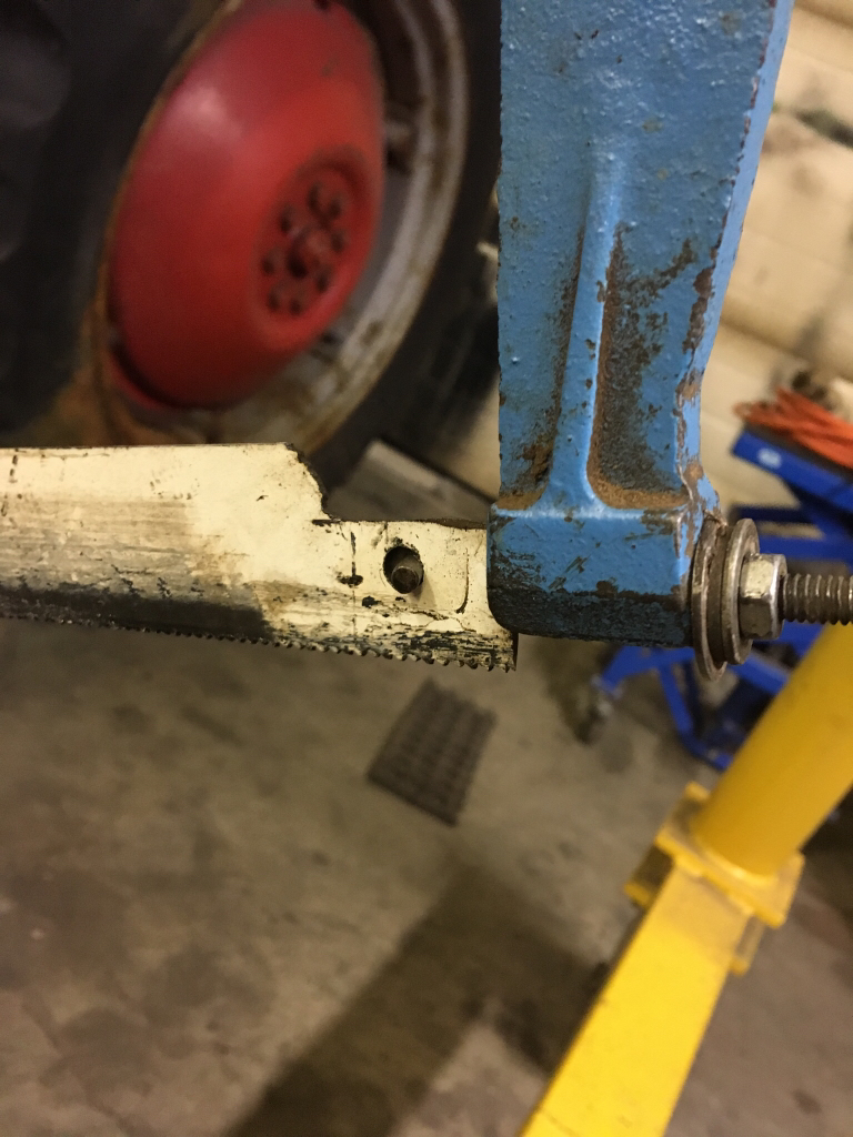
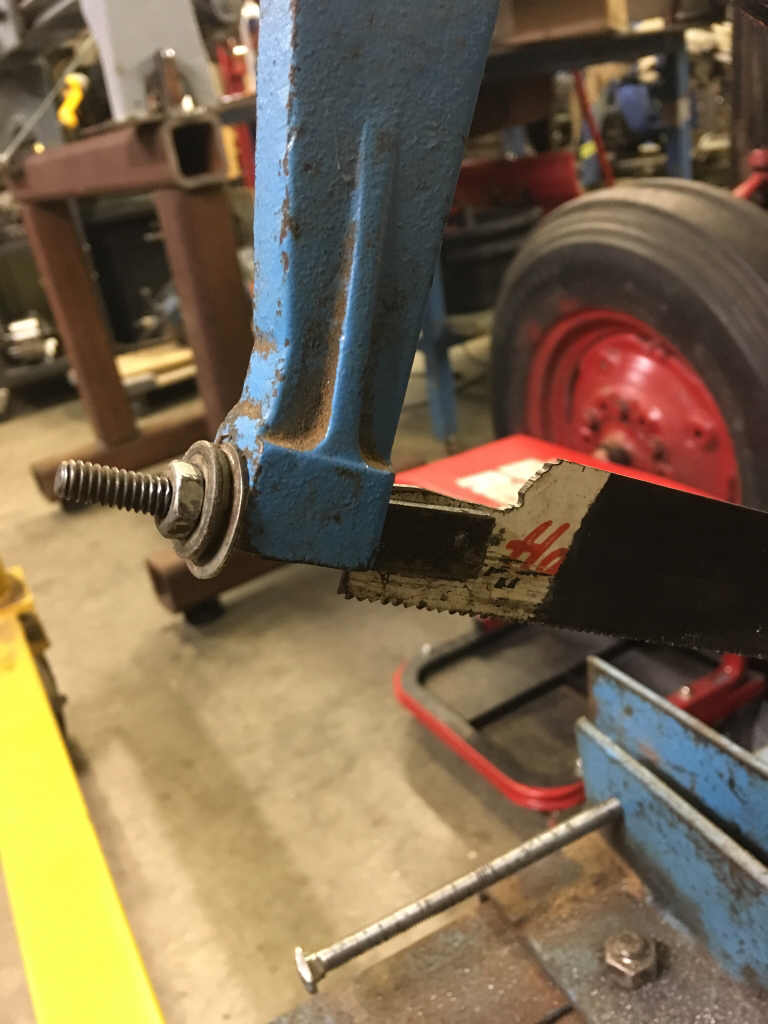
Here is how my blade attaches

90caeee6f8305abcec410fc59ea781fb.jpg


3a840275e2de4b464f400f1e264c1f9a.jpg


Sent from my iPhone using Tapatalk
 

Tom Kitta

Ultra Member
I decided to upgrade my a bit unstable attachment with a set of two bearings - one is for the thrust and the other for usual rotational forces. Both are total overkill but 40mm bearings is what I had on hand. The thrust bearing is from MT4 live centre so it can definitely take some beating. Maybe I post some pics.

I am going to use 3/8-16 screw from the top to apply the pressure to the thrust bearing - I hope it will be enough to make this whole thing stable.

I try first without re-doing the base plate but I probably will have to - Its not a great feeling when a chunk of say 1.5" thick metal sticks out on a 0.5" thread around 20cm from the chuck and goes around 800rpm. I guess I would either have to take very tiny cuts or use some kind of thick sleeve for the 0.5" thread or use some kind of support.
 

kevin.decelles

Jack of all trades -- Master of none
Premium Member
I'm curious about the 5/8 bolt. Mine is nowhere near that size . Can u post a pic of the entire piece you mAde?


Sent from my iPhone using Tapatalk
 

YYCHM

(Craig)
Premium Member
I'm curious about the 5/8 bolt. Mine is nowhere near that size . Can u post a pic of the entire piece you mAde?

TENSIONER1.JPG

TENSIONER2.JPG

TENSIONER3.JPG

Here you go. I chose 5/8" because I wanted lots of meat to thread the blade screw into. Probably over kill.

Without the top notch I found that it canted, so the notch was added to bring the nut bearing surface to the center of the arm slot (if that makes sense).

I'm really impressed with how square it cuts now.

CUT3.JPG

CUT4.JPG
 
Top