• Scam Alert. Members are reminded to NOT send money to buy anything. Don't buy things remote and have it shipped - go get it yourself, pay in person, and take your equipment with you. Scammers have burned people on this forum. Urgency, secrecy, excuses, selling for friend, newish members, FUD, are RED FLAGS. A video conference call is not adequate assurance. Face to face interactions are required. Please report suspicions to the forum admins. Stay Safe - anyone can get scammed.
  • The 2026 Calgary Area Meetup is set for Saturday May 30th at 10am. The signup thread is here! Robinhood has graciously offered to host the meetup again this year. Please note that you MUST RSVP to the notice linked above if you wish to come.

One Second Pendulum Clock

JohnP

Well-Known Member
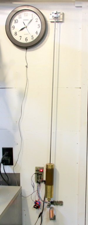
I’ve had this one second pendulum clock with an electronic “Hipp” impulse running in my workshop now for just over 4 years. It is still a work in progress. It keeps reasonable time, in spite of the fact that it is in the un-heated workshop and that the pendulum rod is just a piece of 1/4' dia. 303 stainless. It losses or gains 3-5 minutes a month depending on the temperature fluctuations in the shop. I have a length of carbon fiber tube to replace the stainless one, should improve the time keeping. Just have to get around to making it, also have to improve the suspension unit.
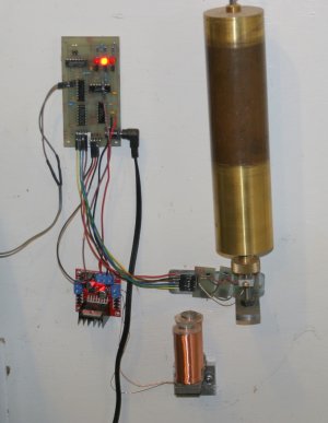
The pendulum bob is a 2" brass tube filled with lead and weighs 4.123 Kg. The drive and timing circuitry are digital logic controlled by a series of 4 hall effect devices which sense the swing of the pendulum and are triggered by a small rare earth magnet on the bottom of the pendulum rod . When the swing decays below a set point the pendulum is given a push, so to speak, by a pulse being sent to the two coils just as the pendulum is approaching them on its swing, attracting the iron bar on the bottom of the pendulum rod, adding the energy back into the system that was lost due to atmospheric drag and friction in the suspension. Initially it was getting an impulse every 20 or so seconds. Today I tried an experiment and put a 15 ohm resistor in series with the coils to cut the coil current in half. It is now giving an impulse every two seconds and occasionally every second. Will have to see if it makes any difference in its time keeping.
The logic circuitry in on the small PC board on the wall to the left of the bob. The small board hanging below it is the driver for the coils. The hall effect devices are in a row directly behind the bottom of the pendulum bob. The whole is powered by a 5V wall wart.
A pulse is sent to the clock on the wall every second to activate the clock movement. The clock movement is just one of those cheap quartz movement that run on a single AA battery that has been modified by removing the battery and disconnecting the internal circuitry from the actuating coil, which is now connected to the pulse coming from the pendulum clock, incrementing the second hand on every swing of the pendulum.
John
clock2.JPG
clockdrive.JPG
 
Nice!

The electronic side of that is way outside my field of experience, but after a bunch of years studying watch and clock making and repair, I have a pretty solid idea of what is being accomplished, even without a compensating pendulum.
 
The way you drive the dial mechanism is very creative. I am building my dial mechanism(s) from scratch but might try it your way as well for an extra one.
I built a Synchronome from a 1960's casting done by a group at TSME. 14 lb lead pendulum.
 
gerritv
Using the cheap quartz movements has one drawback in that, due to the design of the stepper motor that drives the motion, the input pulses to it have to be of alternating polarity (ie +-+-+- etc), which requires a little extra circuitry.
John
 
Love it! Please show more detail on how the pendulum is suspended, how is friction minimized etc.?

What does the driver for the coils do more specifically? voltage, current, time on,? Did you make those coils too?

Temperature fluctuations are a source of error - is that because the stainless rod shrinks/lengthens due to temperature change?
 
Last edited:
John
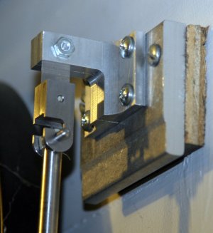
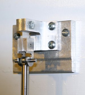
Here are a couple of pics of the suspension which is just a piece of 1/2" x .006" steel feeler gauge material. The suspension is not ideal as, with just the single strip of feeler, the pendulum can twist resulting in it tracing a figure 8 path. Apparently that is not good for accuracy. When I replace the rod I plan to re-make the suspension with two strips slightly thinner separated by about an inch which will prevent any tendency to twist.
Friction in the suspension is minimal. With the pendulum moved off to one side by 2 inches and let go to start it swinging and without the impulse circuit on it will continue swinging for just over 3 hours. The only thing slowing it down is the friction of bending the suspension spring and atmospheric drag.
The coils were wound on the lathe and each consist of 1200 turns of #25 wire which used 215 feet of wire. Each has a resistance of 7.8 ohms. They are connected in series such that the two poles are of opposite polarity, ie one N and the other S. They are driven by a 5V pulse which currently lasts about 250ms. The pulse is timed so that it turns on just before the pendulum reaches BDC in its swing and turns off just before the bar on the bottom of the pendulum rod reaches the centre of the coils ensuring that there is no retarding force on the pendulum.
Yes, currently the main source of error in my clock is the change in length or the stainless steel rod with variation in temperature in the shop. As I said I have a length of carbon fiber tube to replace it with. It has a coefficient of linear expansion that is an order of magnitude less than the steel. With it other things will probably become the dominating factor in its accuracy.
John
Suspention.JPG
Suspention1.JPG
 
Last edited:
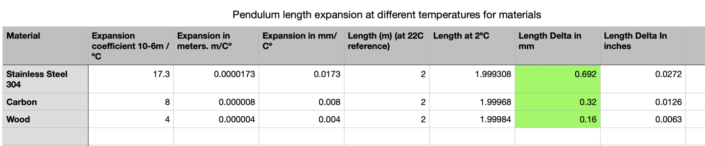
@JohnP that is a very cool project. And I am amazed the pendulum is supported by wire ribbon - I didn't know what a super low friction joint would look like but I didn't expect that! I was looking at a table of coefficients of expansion ( https://www.engineeringtoolbox.com/linear-expansion-coefficients-d_95.html ) and I see wood is similar to carbon fiber!

The inner nerd took over at that point, JAnger must know how much difference does that actually make????... Wood is interesting... but humidity changes wood🙂rolleyes🙂 make it worse than carbon I'm sure.

John please post more results when you upgrade your clock.
1790030757964.png
 
I understand that Beryllium Copper makes the best suspension springs, but I have no idea where to get it in the appropriate thickness (3 - 6 thou).
Wood does make for a low expansion pendulum rod but unless it is coated to prevent moisture absorption its behavior can change unpredictably. It was in fact used, well varnished, in some old long case clocks.
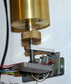
To give an idea of how much changes in length make to time keeping, the rating nut on the bottom that moves the bob up or down to change the time of the swing runs on a 40TPI thread. One eighth of a turn (.003125") changes the time by 3-4 seconds a day.
John
 
@JohnP
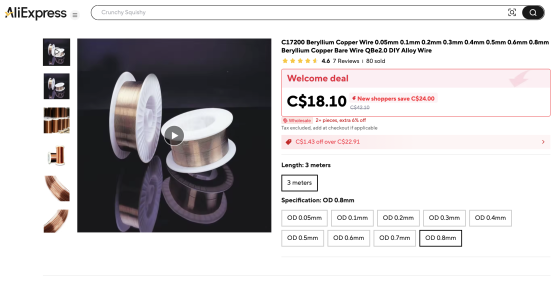
What if you got some thicker beryllium copper wire and press rolled it down to a ribbon? Say this stuff below at 0.8mm. hmmm so 0.004" = ~0.1mm back of the envelope you could roll the wire down to 0.1mm thick and get a 4 or 5mm wide ribbon. My spouse has a jewelry rolling mill - it would do this job easily - so if you like I could try this with some regular copper wire and see what happens.


1790038173530.png
 
John
That's a possibility but at 4-5 mm wide it would definitely need two spaced strips, with just one there would be a real tendency for the pendulum to twist.
Just checked Ali and there is BeCu sheet .1 and .15mm thick, not cheep and the shipping is atrocious. Hadn't thought of looking there.
Just for your interest the formula to calculate the period of a free pendulum is: t=Pi x sq root l/g where t is seconds, Pi=3.14----, l is the length of the pendulum, and g is the local acceleration due to gravity. Units can be anything as long as they are constant. The value of "g" varies depending on where on the earth you are. In my location it is ~ 9.8102 msec-2 ( for you in Calgary it is ~9.80824, less than me, as you are at a higher elevation ie. further from the centre of the earth, ~1100m vice my ~70m ASL). Therefore for a 1 second pendulum the length here would be 9.8102/3.14159x3.14159 = .99398m or 39.133inches. That's from the suspension point to the centre of mass of the whole pendulum. So with a light rod that would be from the top of the suspension unit to slightly above the center of the heavy bob on the bottom.
John
 
Last edited:
How do you adjust and measure your pendulum to 0.99398m ? with a tape I imagine you could get to 0.994m ish. But then what?
Maybe instead of trying to measure the length you time the swing with high -speed video? Or a stop watch and timing the total of 20 swings?

Thanks for the pendulum math.
 
I first wanted to get into machining to make clocks and kinetic sculptures, then automatons. Then I got more interested in modeling.

So more kinetic stuff please and thank you people.
 
John
There are internet sites that have calculators for determining "g" at any location. The one I use is https://www.sensorsone.com/local-gravity-calculator/. They all give an approximation, as a lot of other things can influence it other than lat/long and altitude, like the density of the ground below you.
As far as adjusting the length of the pendulum, the easiest way is to put a piece of, say 3/8" rod, on the bench and a mark the length required further along the bench as close as able with a tape measure . Then with the complete pendulum assembly, lay the bob on the rod and adjust it till it balances, check where the end of the rod is relative to the mark on the bench. Adjust the rod in the bob till the assembly balances and the end of the rod is at the mark. That puts you in the ball park. Mount the pendulum and start it swinging. Time it with a stop watch for say 60 swings. Unless you are extremely lucky it will be considerably more or less than 60 seconds.
To make fine adjustments the bottom of the pendulum rod is threaded and there is a knurled nut ( the "rating" nut) on the bottom that supports the bob, which is free to move on the rod. You then turn the nut to raise the bob, thus shortening the pendulum, if it is running slow, and the opposite if running fast. Repeat the timing. When as close as can be got with the watch, let it run for a day and adjust as necessary, then a month. The last adjustments will be small fractions of a turn of the rating nut. The whole process is called "rating the pendulum".
John
Rating Nut.JPG
 
Back
Top