JohnP
Well-Known Member
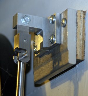
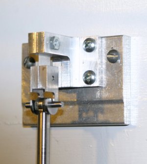
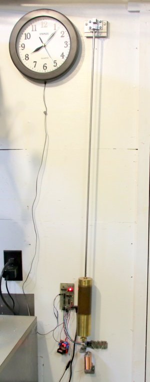
I’ve had this one second pendulum clock with an electronic “Hipp” impulse running in my workshop now for just over 4 years. It is still a work in progress. It keeps reasonable time, in spite of the fact that it is in the un-heated workshop and that the pendulum rod is just a piece of 1/4' dia. 303 stainless. It losses or gains 3-5 minutes a month depending on the temperature fluctuations in the shop. I have a length of carbon fiber tube to replace the stainless one, should improve the time keeping. Just have to get around to making it, also have to improve the suspension unit.
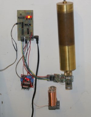
The pendulum bob is a 2" brass tube filled with lead and weighs 4.123 Kg. The drive and timing circuitry are digital logic controlled by a series of 4 hall effect devices which sense the swing of the pendulum and are triggered by a small rare earth magnet on the bottom of the pendulum rod . When the swing decays below a set point the pendulum is given a push, so to speak, by a pulse being sent to the two coils just as the pendulum is approaching them on its swing, attracting the iron bar on the bottom of the pendulum rod, adding the energy back into the system that was lost due to atmospheric drag and friction in the suspension. Initially it was getting an impulse every 20 or so seconds. Today I tried an experiment and put a 15 ohm resistor in series with the coils to cut the coil current in half. It is now giving an impulse every two seconds and occasionally every second. Will have to see if it makes any difference in its time keeping.
The logic circuitry in on the small PC board on the wall to the left of the bob. The small board hanging below it is the driver for the coils. The hall effect devices are in a row directly behind the bottom of the pendulum bob. The whole is powered by a 5V wall wart.
A pulse is sent to the clock on the wall every second to activate the clock movement. The clock movement is just one of those cheap quartz movement that run on a single AA battery that has been modified by removing the battery and disconnecting the internal circuitry from the actuating coil, which is now connected to the pulse coming from the pendulum clock, incrementing the second hand on every swing of the pendulum.
John
The pendulum bob is a 2" brass tube filled with lead and weighs 4.123 Kg. The drive and timing circuitry are digital logic controlled by a series of 4 hall effect devices which sense the swing of the pendulum and are triggered by a small rare earth magnet on the bottom of the pendulum rod . When the swing decays below a set point the pendulum is given a push, so to speak, by a pulse being sent to the two coils just as the pendulum is approaching them on its swing, attracting the iron bar on the bottom of the pendulum rod, adding the energy back into the system that was lost due to atmospheric drag and friction in the suspension. Initially it was getting an impulse every 20 or so seconds. Today I tried an experiment and put a 15 ohm resistor in series with the coils to cut the coil current in half. It is now giving an impulse every two seconds and occasionally every second. Will have to see if it makes any difference in its time keeping.
The logic circuitry in on the small PC board on the wall to the left of the bob. The small board hanging below it is the driver for the coils. The hall effect devices are in a row directly behind the bottom of the pendulum bob. The whole is powered by a 5V wall wart.
A pulse is sent to the clock on the wall every second to activate the clock movement. The clock movement is just one of those cheap quartz movement that run on a single AA battery that has been modified by removing the battery and disconnecting the internal circuitry from the actuating coil, which is now connected to the pulse coming from the pendulum clock, incrementing the second hand on every swing of the pendulum.
John