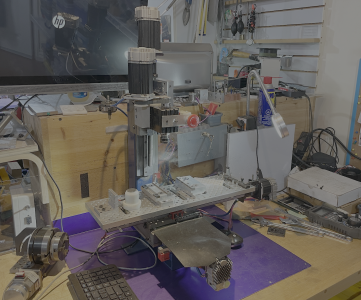
I bought this originally as a very basic manual mill about 20 years ago.

Today it is completely pimped out, with Teknic Clearpath servos, a PlanetCNC controller, the Saunders Machine Works tooling plate bed with a dual station free vice setup and a rotary axis.


All that bling came at a price - headroom. With the vice in place, and a small drill chuck in the spindle, there was about 30mm of working headroom which was a big limitation. The second itch was that I wanted some way of coordinating the spindle with the A and X axes for gear hobbing and decorative work. And thirdly the ER-16 collets it used limited the tooling to 10mm diameter - and bigger is better, they say.
The headroom was an easy fix - the original head mounted on a rail which was drilled every 2". I just shifted the whole assembly up one hole and voila! 2" headroom.
I had an ER-20 collet holder on a 20mm shaft and a 3-1/2" lump of 6061. So The job was to make a high speed (4000 rpm) spindle with as close to zero runout as possible, figure out how to incorporate an encoder and the eStop switch and get it all done by dinner time.

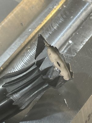
After squaring up the 6061, the dovetail mount was cut with a 3/4" 45degree cutter, which shattered just before the last inch was cut. New cutter. Aluminum. Moderate feedrate. Go figure.

Then it was just plain boring.


The bearings slip smoothly into the bores - three in total.


The spindle was turned in the 4 jaw to 16mm for the pulleys, and a 3/4"-24 threaded portion for the 'pre-load' nut. Since the lower bearing bore was 1", I turned a 1045 sleeve fitted to press fit on the 20mm ER-20 shaft. These are deep groove ball bearings, twice the size of the OEM spindle bearings, and they are assembled with a moderate pre-load.
There is a collar and bearing protector fitted to the lower end of the spindle which was pinned in position and turned true, without disturbing the 4 jaw setup.
I screwed that up though, boring the protector just a little oversize, so thats why there's knurling at the end of the sleeve.
The trick I have found for making simple spindles like this, is to use the collets themselves to find the true centre - so here I used a piece of 1/2" precision ground, trued in the 4 jaw then held in the ER-20 collet. After all, its the inside of the shaft that's important, not the outside where we would normally run an indicator. The tail of the work is supported by the tailstock, or if it were longer or thinner, by the fixed steady as well as the tailstock. The runout on this spindle does not register at all on a 5 tenths DTI.

Test fitting the basic assembly.


The finished head looking sexy in metallic blue.

The encoder uses a GT-2 belt and the spindle is an XL belt. All the grey pulleys are 3D printed in PETG and run true. The spindle pulley is press fitted with loctite onto a steel hub.


There's even a matching ER-20 collet rack

And no, it wasn't done by dinner time. 😀
Today it is completely pimped out, with Teknic Clearpath servos, a PlanetCNC controller, the Saunders Machine Works tooling plate bed with a dual station free vice setup and a rotary axis.
All that bling came at a price - headroom. With the vice in place, and a small drill chuck in the spindle, there was about 30mm of working headroom which was a big limitation. The second itch was that I wanted some way of coordinating the spindle with the A and X axes for gear hobbing and decorative work. And thirdly the ER-16 collets it used limited the tooling to 10mm diameter - and bigger is better, they say.
The headroom was an easy fix - the original head mounted on a rail which was drilled every 2". I just shifted the whole assembly up one hole and voila! 2" headroom.
I had an ER-20 collet holder on a 20mm shaft and a 3-1/2" lump of 6061. So The job was to make a high speed (4000 rpm) spindle with as close to zero runout as possible, figure out how to incorporate an encoder and the eStop switch and get it all done by dinner time.
After squaring up the 6061, the dovetail mount was cut with a 3/4" 45degree cutter, which shattered just before the last inch was cut. New cutter. Aluminum. Moderate feedrate. Go figure.
Then it was just plain boring.
The bearings slip smoothly into the bores - three in total.
The spindle was turned in the 4 jaw to 16mm for the pulleys, and a 3/4"-24 threaded portion for the 'pre-load' nut. Since the lower bearing bore was 1", I turned a 1045 sleeve fitted to press fit on the 20mm ER-20 shaft. These are deep groove ball bearings, twice the size of the OEM spindle bearings, and they are assembled with a moderate pre-load.
There is a collar and bearing protector fitted to the lower end of the spindle which was pinned in position and turned true, without disturbing the 4 jaw setup.
I screwed that up though, boring the protector just a little oversize, so thats why there's knurling at the end of the sleeve.
The trick I have found for making simple spindles like this, is to use the collets themselves to find the true centre - so here I used a piece of 1/2" precision ground, trued in the 4 jaw then held in the ER-20 collet. After all, its the inside of the shaft that's important, not the outside where we would normally run an indicator. The tail of the work is supported by the tailstock, or if it were longer or thinner, by the fixed steady as well as the tailstock. The runout on this spindle does not register at all on a 5 tenths DTI.
Test fitting the basic assembly.
The finished head looking sexy in metallic blue.
The encoder uses a GT-2 belt and the spindle is an XL belt. All the grey pulleys are 3D printed in PETG and run true. The spindle pulley is press fitted with loctite onto a steel hub.
There's even a matching ER-20 collet rack
And no, it wasn't done by dinner time. 😀