• Scam Alert. Members are reminded to NOT send money to buy anything. Don't buy things remote and have it shipped - go get it yourself, pay in person, and take your equipment with you. Scammers have burned people on this forum. Urgency, secrecy, excuses, selling for friend, newish members, FUD, are RED FLAGS. A video conference call is not adequate assurance. Face to face interactions are required. Please report suspicions to the forum admins. Stay Safe - anyone can get scammed.

My first mill is a First mill

Like the man sings: Two out of three ain't bad:

I made up a little locking stud to sit in the nubbin on the side of the mill that probably held something similar in the past.
X was very straightforward. Had a little block of aluminium lying around that made a good standoff. The angle bracket came with the "kit". Just needed trimming and tapping. I probably need an second point of contact instead of that one cap screw holding it together, but I'll assure myself I'm happy with the setup before putting another hole in the y-slide.

Y was a little trickier, but easier to make up. Just a little extender for the bracket, a bunch of threaded holes and cap screws. The holes under the X-slide were already there, 1/4-20, so I grabbed my (only?!) 1/4-20 screw to hold it in place. I'll drill another hole there once I'm satisfied, and trade the screw for a proper cap screw.

Z I'm still thinking about. A lot of plumbing and faired surfaces all around getting in the way. Probably still easy, but I've had enough for tonight.

Your mill looks the same as mine. I used some epoxy filler to level out my base for the Z scale. I am still working on my Z2 - Quill scale. It's not really necessary but why not? Does your dro box have a 4th DB9 plug on the back?

Here is a link to my install - just skip over all the undrillobillium stuff. I think my Z - axis turned out great.

Thread 'Installing a DRO on a Hartford Bridgeport Clone.' https://canadianhobbymetalworkers.com/threads/installing-a-dro-on-a-hartford-bridgeport-clone.4852/
 
I used some epoxy filler to level out my base for the Z scale.
I might yet. I think I can move the scale back on the knee far enough to be clear of obstructions and wind up with an easier time mounting the sensor to the curves of the body.
Does your dro box have a 4th DB9 plug on the back?
No, it's perhaps a little too cost-optimized. I'm pretty sure I could open it up and run another DB9 to a header on the board - cost optimization also means these are all the same driver board...
 
No, it's perhaps a little too cost-optimized. I'm pretty sure I could open it up and run another DB9 to a header on the board - cost optimization also means these are all the same driver board...

Ya, exactly my thinking as I was haggling with them on the cost. It really doesn't cost as much as the retail suggests it does. That extra db9 connector is less than a buck.

But no matter. I've been using mine without the quill for a while now. It really wouldn't be a big deal if I never get it working. Nobody uses a quill for fine adjustments. So I can put the quill and knee where I want them, lock the quill, zero the Z, and then go!

I have used my lathe(s) without a DRO for a half century. I never missed it. But know that I have a DRO on my mill, my lathe is jealous......
 
I have used my lathe(s) without a DRO for a half century. I never missed it. But know that 8 have a DRO on my mill, my lathe is jealous......
Half a year in my case, and it took me only milling the one mounting block for my X-axis to understand how much the DRO is table stakes for a mill. Wow - was it ever easier to hit my dimensions and through hole locations, even with just the Y installed.
The lathe can wait a little longer - all the cutting travel is in the same direction, after all.
 
Is this bracket going to run into the column if you crank the table back far enough?

fs-aU9uvot5zS7zOrX8OfhFa3PGIDGQGlqcL6mjAuWtkfvxQ_AQqcEtXjnbfZ5Zxywtde2eU6fqImFa7incrHIl35EYukIWfWJcRtuT0cTjorHO01BWMFmWv53nk0yUjqvkmkUAAzju4MTOwQbvaxfCl17AolaIZr01LcAj_-tz2A8pMs4dYZGFg5Y8ppduEfmop3w4ZLOpTX5NeYFebX2ogr4yh296AuKgbz9TjsTGaqmUBSNUI4jE2j_qiNXtS__MtzvCfN3JsocCKUE9fllyDEVdUB7l8j07QzesdRZpIcl6z9kLJ5FDkvPW8Dt3-bFY9iUqqIQf5eYkSR8x9QmCZiBJhQVryX7y4mswCJRGa9pIohsWHyO3-MUYdMZte1EZPFc-1ERk8Jwe1CZRsUPzqzVwaXrfKfiszot-A1CFYQZ8WRH1jdS8dYAMgVMOHbZ-cZnWqcr6p-TKGsk11pMyUWwVCLYMcyrKRL53sRtvDqvCAQsHEueBnE7veDY1qhiHCTSfYIfMHsz8qAoKpp-1Uorc887_lVTQ9UF-dOhakVAj_1rcsyq3FfUqWrgVNG9Rt2Qxf1Y8Q9t3W07bA3iU1Dqg1CbXOqybP5ZE7MC3pNqXXtoiGqGyvOlA6pRR2B5wBwxaEKrBBKyM7fd6ZKwTag71BZ_eVu9xNeEiA1fIDpX-C9uyykRALjIkkle15qHOZn3vbvkA_1fEmXOFRyIGjf-moSNtx_6aNoVHPNUOveX-bP-ZnBlJh0EwSozaJtLLRA6wvHKUiVk7rMIhRfvEbH_5ZSYdsww=w1026-h1362-no
 
Half a year in my case, and it took me only milling the one mounting block for my X-axis to understand how much the DRO is table stakes for a mill. Wow - was it ever easier to hit my dimensions and through hole locations, even with just the Y installed.
The lathe can wait a little longer - all the cutting travel is in the same direction, after all.

My mill experience is virtually the same as yours. Roughly half a year of turning wheels, counting turns, measuring, creeping up on dimensions, measuring again.

I made my first DRO bracket (X) the old fashioned way. Then I did a bunch of testing to see how reliable and repeatable it was. WAY beyond my expectations. Then with DRO-X working, I made my Y brackets......... HOLY FG CRAP!

I thought I had died and gone to heaven. I would NEVER go back.

Did you get a digital edge finder yet? If not GOYA GOYA! Trust me on this one. It's another amazing step forward.

I like the Accusize and the Fowler. Both work really well.

Still noodling how to edge on Z. Another project for some day. For now I like what @thestelster showed us.
 
Is this bracket going to run into the column if you crank the table back far enough?

Yup. At least mine did. In fact, even the scale hits without the sensor. I could not mount it far enough over to avoid that So I put a small block on the slides to stop that from happening. My plan is to install a rubber stop and mount the vise back a bit more.

Edit - mine also has a stop screw that I could move. But I think a rubber stop is better.
 
My mill experience is virtually the same as yours. Roughly half a year of turning wheels, counting turns, measuring, creeping up on dimensions, measuring again.

I made my first DRO bracket (X) the old fashioned way. Then I did a bunch of testing to see how reliable and repeatable it was. WAY beyond my expectations. Then with DRO-X working, I made my Y brackets......... HOLY FG CRAP!

I thought I had died and gone to heaven. I would NEVER go back.
I second that. I have a Shumatech DRO-350 on mine using the cheap scales. This was back in 2006 before the Chinese stuff started showing up making it impossible for North American manufacturers to compete. Mine was a kit and more expensive in 2006 dollars compared to the fully assembled systems you can get now.

@PaulL Are you going to put shields over yours like @Susquatch did?

Here's mine for the Y axis. And to be truthful I never did the X.
DustShieldYAxis.webp
 
Ya, my vise contacts the column before the scale reader as well. Without something in place a y-axis PF could prove disheartening.
It's very tempting to drop a couple of hall effect sensors on a board and understand how the thing really works...
 
Only if it looks like they will be useful. The little rubber sweeps look like they do most of the job already.
As you can see even
20220819_103031.jpg
the Y axis gets crap dropped on it.
Ignore the surplus printer switches.
All that will change when I upgrade to ball screws.
 
It's very tempting to drop a couple of hall effect sensors on a board and understand how the thing really works...

Not sure what you are wondering about here Paul.

If you are wondering how the scales and reader head works, I don't think hall effect will tell you much.

I had wondered how the magnetic sensors worked myself. The research I did suggested that the sensor picks up the phase difference between magnetic fields on the scales. This phase difference is then converted to a string of digital pulses that are counted in the display unit. I'm pretty sure I wrote something up on it elsewhere on the forum. I just can't find it right now.
 
If you are wondering how the scales and reader head works, I don't think hall effect will tell you much
My understanding is that the differential field reading between two nearby heads lets you calculate the position between two magnetic peaks on the strip. So I get this unaccountable urge to work out the details.
 
@Susquatch @PaulL I got introduced to DRO on a mill in 1981. Loved it. Got my own mill in about '90 - no DRO. I could work it, but I vowed I'd get another mill before long with 2 things: a moveable ram like a BP/BP clone, and a DRO. around '2004, I got one, then sold my old mill to Janger, who then sold it to someone else.

Using a mill without a DRO is like driving a car with flat tires. you cannot get anywhere fast.
 
@PaulL All DROs, digital verniers work in a very similar way: think of an optical vernier - each line on one side corresponds to a detector, and the other lines are the thing detected. With a DRO the added thing is to enhance the effect with quadrature detection, which gives you about 4X the resolution for a given scale.
 
@PaulL All DROs, digital verniers work in a very similar way: think of an optical vernier - each line on one side corresponds to a detector, and the other lines are the thing detected. With a DRO the added thing is to enhance the effect with quadrature detection, which gives you about 4X the resolution for a given scale.
This is why I got curious about the magnetic ones. The lines aren't as tight as optical, though placed quite accurately but ridiculously far apart - 5mm and 1mm are typical. The dual sensors let you play differencing games to get better resolution. Add better integration technology/math (the quadrature part) and somehow they get 1000 times better resolution than the encoder strip has.
 
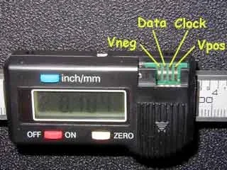
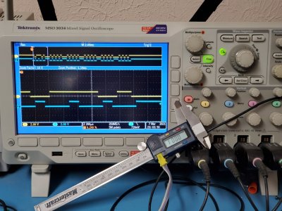
What gauge did you adapt? Did it come with continuous SPC out or is did you have to abuse it particularly?
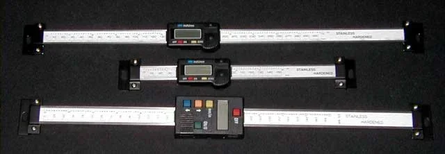
These are the scales.

The only major change is I removed the battery and made a module that was shaped and worked electrically like the battery but had capacitors.
 

Attachments

  • connector.webp
    connector.webp
    21.5 KB · Views: 1
  • scales.webp
    scales.webp
    15.9 KB · Views: 1
  • ScaleTest.jpg
    ScaleTest.jpg
    378.7 KB · Views: 1
Back
Top