Mr Crispin grinds his jaws

Dabbler

ersatz engineer
I posted in one of the other threads about ROBRENZ truing his lathe chuck jaws.

MrCrispin does it an alternate way. I think it is wonderful when you have to very skilled guys do essentially the same thing different ways. This helps me at least to discover the important things and distinguish them from the less important things....

 

Susquatch

Ultra Member
Administrator
Moderator
Premium Member
Nice!

Of course many of us very lucky SOBs have two part jaws which allow the pin method he mentions that Renzetti uses.

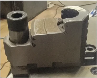
Since my mind was unpulluted by any previous approach, I used a third method which was to use longer screws in my jaws with sleeves. The sleeves were turned to the same diameter as the socket head screw heads so both the sleeves and the heads sit significant proud of the jaw surface to serve as locations to hold the ring. The obvious advantage of this arrangement over Renzetti's is that the so-called pins are thus solidly mounted and cannot accidentally fall out in the middle of an operation.

Being a guru role-model archival curator of parts and stock and old junk, (often erroneously and maliciously called a "hoarder" by less gifted individuals) I found an old 4 inch (5 OD) socket in my archives which I then cut off to use as a ring. And of course, I suitably archived the rest of the socket to use as a future stock for something.

Then mounted the whole thing up in preparation for grinding. Then discovered that it was all for naught as my jaws were already concentric and all my work was just a pessimistic needless adventure to solve a problem I didn't even have!...... :rolleyes::mad::(

If you can, try to imagine an old man pouting in a corner trying to figure out why he didn't measure the concentricity FIRST! WTF! I've turned all kinds of stuff! Surely, I must have noticed that my 3-jaw concentricity was pretty darn good as is. But nope, not this hairy old fool. If he did notice, it didn't sink in!

Please accept a little advice @Dabbler: As you search around for a really nice 3 jaw, make sure you get one with two-part jaws... ;)
 
Last edited:

Dabbler

ersatz engineer
Please accept a little advice @Dabbler: As you search around for a really nice 3 jaw, make sure you get one with two-part jaws... ;)

I've been looking for one for my big lathe - rumour has it that one day I'll find a great *bargoon* if I look hard enough. Perhaps I'll just depend on a good friend to find one for me - nudge nudge, wink wink... :p
 

Susquatch

Ultra Member
Administrator
Moderator
Premium Member
Here are 2 photos of how I did mine.

20230818_092149.jpg

20230818_092253.jpg

One can see that the sleeves were just made from old bolts my most favorite source for round bar stock. The remnants of the thread roots are still visible.
 

Susquatch

Ultra Member
Administrator
Moderator
Premium Member
Here is the left over part of the socket retrieved from my archival storage.

20230818_093921.jpg

Not sure what it will be someday. Maybe grind the inside jaws? Gotta be careful not to measure them first though. Don't want to spoil my fun too early!
 

PeterT

Ultra Member
Premium Member
If I'm understanding your pre-grind setup correctly - I believe it's better (necessary) to locate your bolt/pin extension on the inside hole, not the outside hole. You want the preload acting so that the jaw surface is deflecting outward under scroll load mimicking what will be uniform clamping along the part. That's why in all cases of these various preload retention devices (Crispin, Stefan, Renzetti, DeeDee...) the clamp or pin or whatever fixture device is positioned to act inwardly as close as practically possible to the jaw surface.

Renzetti does a good job of describing & quantifying ~ 5 min mark.

1692377662602.png 1692376817409.png
 

Attachments

  • 1692376761616.png
    1692376761616.png
    619.7 KB · Views: 2

Susquatch

Ultra Member
Administrator
Moderator
Premium Member
If I'm understanding your pre-grind setup correctly - I believe it's better (necessary) to locate your bolt/pin extension on the inside hole, not the outside hole.

I believe you understand what they advocate correctly.

However, I'm never one to accept such things cart blanche. I assessed the force diagrams myself and reasoned that applying the force at any pin or bolt head placed in any of the screw holes would serve the same purpose. The only difference is magnitude. The inner screw hole would just cant the jaw nose more than the one at the rear, but both would bias the loads correctly. Both locations end up trying to twist the Jaws as you show in your arc. Both lines of force are applied at the base of the Jaws. The moment arm for the inside hole is b) , and the outside is a) as I have shown here.

1692376761616~2.png

I think most of the points they were making (which I confess I didn't watch cuz I hate YouTube) probably apply in the case of an internal ring that applies force at the back of the Jaws where there is no twisting moment arm. (I infer this from the Crispin video which I did watch at @Dabbler recommendation) I do agree with this point. But almost any location at the front of the Jaws (internal or external) will apply the correct bias.

In other words, both apply a bias, but my choice is a lower bias than it would have been using the center screw holes.

In my own judgement, I thought that was a better choice. Each to his own as they say.
 

PeterT

Ultra Member
Premium Member
Yup, to each to their own. You have often mentioned your hate of YouTube videos. So it is what it is, that's on you. Personally I think there is a lot of YT garbage out there, but also some good stuff by people with substantial experience & non-conflicting ego or commercial bias. The trick is distinguishing between them & posers. No different than a book or magazine or technical journal or.... If I said I don't read books because they bore me, its hard to imagine I would have a complete picture of any subject, or at least without some selective information bias. Again, to each to their own & now we are off topic.

If you set up a dial on the jaws to physically corroborate your theory it would be interesting to see results. Of course tight scroll & good condition jaws may be minimal & different than a worn chuck... which are usually the candidates for regrinding in the first place unless its a transplant from another machine or some other issue.
 

Susquatch

Ultra Member
Administrator
Moderator
Premium Member
Personally I think there is a lot of YT garbage out there, but also some good stuff by people with substantial experience & non-conflicting ego or commercial bias. The trick is distinguishing between them & posers. No different than a book or magazine or technical journal or.... If I said I don't read books because they bore me, its hard to imagine I would have a complete picture of any subject, or at least without some selective information bias. Again, to each to their own & now we are off topic.

Yes, but it is a good topic. And I confess I screwed up. My apologies. Anyone who goes to the trouble of giving me a time mark to fast forward to deserves an effort on my part to try it. I didn't do that so shame on me. That plus I do respect your recommendations, and I didn't bother to check them out. Shame on me AGAIN.

Instead, I assumed I understood your point and ignored the video. I have now watched it as per your recommendation.

All the above said, it turns out that I actually did understand where all this was going. It also turns out that the location Robin chose isn't actually either screw hole. Instead he mounted a ring in the stress relief groove (or clearance groove) at the highest step in the Jaws. As luck would have it, that is even a bit lower leverage arm than what I chose. So I think my results would be the same as his.

That said, it's an interesting thing to check. I like to say "absolutely everything moves. It isn't if it will move, it's only how much will it move". Robin says "Everything is rubber." His is a much simpler way to view it.

When I get the time, I'll measure everything the way that he did.

Again Peter, my apologies. A good debate and differences of opinion are desirable aspects of any technical discussion. But ignoring your specific video recommendations after you went to the trouble of giving me a time reference and jumping over your point, whether or not I understood it, was a very poor showing on my part. You deserved much better than that from me, and I apologize for that.

Last but not least, for some reason, it seems I don't even have Renzetti pegged right. He isn't who I thought he was. No idea how I messed that up. I noticed a lot of good content while I watched that video. So I'm going to make a point of watching a few more of his videos because I'm virtually certain that I'll learn more than a few things worth knowing.
 

PeterT

Ultra Member
Premium Member
No worries. I have 2 part reversible jaws on some chucks as well. They are in pretty good shape but it can't stop my mind to wandering for 'one day' when its required or I inherit something that needs remediation. I had the same general idea as you have shown (if I understand it correctly) & I think I've seen variations to the theme elsewhere. But there may still be some devil in the details.

If the dummy pin extension has any kind of clearance to the jaw hole counterbore, which it pretty much has to have to get in the hole, then loading the protruding pin segment against the ring is only bending the dummy pin independent of the jaw. The pin is anchored at the base of mount hole, so its basically deflecting like a cantilever beam until/if it ever makes contact with the jaw. That is not the same loading mode as a stop or notch or pin located at the upper jaw surface face and very near the jaw grip surface. I was thinking of some kind of tapered cone extension that makes tangent contact with the counterbore lip. But that would only work on the outer hole, not the inner hole where its most desired. Even so, looks dodgy & complicated to me.

I think the Crispin clamps are a better solution. Easy to make. They don't involve drilling pin holes into the jaws (Stefan) or relief notches (Renzetti). Not to say these methods are bad, just a few pay grades above my tooling & experience. I don't think my quick & dirty hardness testing was definitive but my jaws are pretty damn hard, so it cooled my jets about drilling with carbide.

1692395328880.png 1692395413198.png 1692395666492.png
 

PeterT

Ultra Member
Premium Member
DeeDee made this adjustable ring type fixture which loads on the jaw facets either side of clamp area. Could be used for solid or 2-piece jaws. Its a little more involved than Crispin clamps but I think comparable end result. You may have to play it at 10X speed, but the shop mascot is kind of cute LOL.

1692396275719.png


Susquatch

Ultra Member
Administrator
Moderator
Premium Member
If the dummy pin extension has any kind of clearance to the jaw hole counterbore, which it pretty much has to have to get in the hole, then loading the protruding pin segment against the ring is only bending the dummy pin independent of the jaw. The pin is anchored at the base of mount hole, so its basically deflecting like a cantilever beam until/if it ever makes contact with the jaw. That is not the same loading mode as a stop or notch or pin located at the upper jaw surface face and very near the jaw grip surface. I was thinking of some kind of tapered cone extension that makes tangent contact with the counterbore lip. But that would only work on the outer hole, not the inner hole where its most desired. Even so, looks dodgy & complicated to me.

I think you are over analysing it. Of course the bolt or pin or whatever will bend. Everything moves, or as Renzetti says, everything is rubber. But it doesn't matter how much it bends

Think of the bending pin a bit like a wrench handle bending as you apply a torque. The torque on the part is the same regardless of whether the handle bends or not. The moment applied to the Jaws is the force x the length of the moment arm. There is no term for how much the arm bends. Both are loading the Jaws in the direction required to grind or machine them such that they will hold the part at the business end of the chuck most firmly.

We can always debate about how much is enough though.....
 

RobinHood

Ultra Member
Premium Member
No worries. I have 2 part reversible jaws on some chucks as well. They are in pretty good shape but it can't stop my mind to wandering for 'one day' when its required or I inherit something that needs remediation. I had the same general idea as you have shown (if I understand it correctly) & I think I've seen variations to the theme elsewhere. But there may still be some devil in the details.

If the dummy pin extension has any kind of clearance to the jaw hole counterbore, which it pretty much has to have to get in the hole, then loading the protruding pin segment against the ring is only bending the dummy pin independent of the jaw. The pin is anchored at the base of mount hole, so its basically deflecting like a cantilever beam until/if it ever makes contact with the jaw. That is not the same loading mode as a stop or notch or pin located at the upper jaw surface face and very near the jaw grip surface. I was thinking of some kind of tapered cone extension that makes tangent contact with the counterbore lip. But that would only work on the outer hole, not the inner hole where its most desired. Even so, looks dodgy & complicated to me.

I think the Crispin clamps are a better solution. Easy to make. They don't involve drilling pin holes into the jaws (Stefan) or relief notches (Renzetti). Not to say these methods are bad, just a few pay grades above my tooling & experience. I don't think my quick & dirty hardness testing was definitive but my jaws are pretty damn hard, so it cooled my jets about drilling with carbide.

View attachment 37593View attachment 37594View attachment 37595
I like the discussion on this topic. Very valid points raised all around.

I “drilled“ my solid part 3J Röhm chuck jaws with a TTC branded 1/8” solid carbide, 4 F, center cutting end mill. The jaws are hard, but they can be machined. Then the “pin & ring” method was used to pre-load the jaws for grinding.

On my two-part Pratt Burnerd 3J chuck jaws, I used bolt extensions sleeves and longer bolts with a ring in the inner hole (green drawing). The SHCS are M10 or M12, so pretty substantial, and provide enough compressive force on the sleeve to resist bending as you worry Peter. I am sure they bent, but not so much that the system would not preload properly.

Remember, the preload is only so much as you would “normally, reasonably tighten down on a part”. Which is not that much once the jaws grip things properly. I rarely gronk onto parts. You actually lose grip if you do, because you deform the chuck body and thus reduce the contact surface between the jaws and the part.

Once the jaws are ground in, one can see (& feel) the contact onto the part starting at the tip of the jaws and moving back into the hole as the same / similar torque is applied as the preload for grinding. Once you have full length surface contact, there is a definite “stop” beyond which the chuck key does not want to go any more - except with a large, additional force on the T-handle.

I have done 2 of my 3J chucks so far. The others (for the bigger lathe) are on the list TBD... It is so much better to use the chucks once done.
 

PeterT

Ultra Member
Premium Member
I think you are over analyzing it.
Actually upon reflection I think I am contradicting myself. Assuming the pin is screwed firmly into the bottom of counterbore with normal torque as it should be, then the jaw parts (red + blue + green) are essentially one body. So ring force on the extended pin will displace the entire jaw body against the scroll threads & still create a clockwise moment on the jaw face relative to the T-slot. A counterbore clearance between pin & hole is really of no consequence. I've drawn a jaw retention bolt through a hollow pin but that's a bad idea me thinks, better to turn a pin with threaded end so its solid.

1692404287909.png
 
Last edited:

Dabbler

ersatz engineer
I was going to chime in, and was considering my points, but RH said most of it far better than I could.

Just a quick point about using the inner or outer bolts: The only thing that matters in the force diagram is the distance from the boxway of the jaw, not any perceived angle. All you are doing is contriving to 'lift' the rear contact edge of the jaw. This is 100 % controlled by the height above the jaw, not the location of the force from centre. [edit] Centre of the chuck.

What might wreck this is if the device pressing on the jaw gets too arcane - for instance somehow using both bolts - which is tempting, but that will be a different force than a normal tightening force used to hold a part.

...None of these methods is perfect - nor do they have to be - they only have to create the same lift in each jaw with approximately the same force as is used to hold a part. You get no benefit at all using a solid pin versus thread instead of a tube (nor any liability). The lift component will be the same no matter how the pin and it's sleeve bends. You are thinking too hard about how the pin bends, and not looking *only* at the lift component as a result of a given force from the scroll. That is the *only* thing that matters here.

Renzetti, Crispin and Gotteswinter all do this differently and get the *same* result. From that you can deduce above paragraph.
 
Last edited:

PeterT

Ultra Member
Premium Member
I “drilled“ my solid part 3J Röhm chuck jaws with a TTC branded 1/8” solid carbide, 4 F, center cutting end mill. The jaws are hard, but they can be machined. Then the “pin & ring” method was used to pre-load the jaws for grinding.
Interesting. How deep were the pin holes? I've heard of using center cutting EM over drills to make straighter holes in certain situations or minimize skating off spot drills, but are there other reasons (over ~same length carbide drill)? Did you set up chuck on RT to get same radial spacing of holes, or am I over-thinking again haha.

Another factor, maybe I missed discussion in videos, its been a while. Is the pre-grind open position supposed to be the average of diameter you most work on, or a min or max? What I'm getting at is the grind radius vs the part radius. Its never going to match a part except by chance but is it better to have predominant part contact tangent within jaw grind (favoring a wider opening) or vise-versa?
 

Susquatch

Ultra Member
Administrator
Moderator
Premium Member
Actually upon reflection I think I am Under-analyzing it.

Too funny. That's usually me!

Assuming the pin is screwed firmly into the bottom of counterbore with normal torque as it should be, then the jaw parts (red + blue + green) are essentially one body. So ring force on the extended pin will displace the entire jaw body against the scroll threads

Yes. And it needs to do that in order to take up any backlash in the scroll.

& still create a clockwise moment on the jaw face relative to the T-slot.

Yes. And this moment force is the one that matters cuz that's the one that lifts the jaw end and compresses the other end. This is the force that is needed in order to get the nose of the jaws to tighten first.

A counterbore clearance between pin & hole is really of no consequence.

Agreed. It's just rubber. So what if it bends.

I've drawn a jaw retention bolt through a hollow pin but that's a bad idea me thinks, better to turn a pin with threaded end so its solid.

Nah, it's ok. It's only purpose is to create a moment or leverage to bias the jaw position as it is machined. Personally I like the sleeve and screw because it's super easy to make and presents a nice rounded surface for the pressure ring to press against.

@RobinHood & @Dabbler have described the situation differently but I agree with them.

Man, I wish I could do Fusion like you do!
 

Dabbler

ersatz engineer
but is it better to have predominant part contact tangent within jaw grind (favoring a wider opening) or vise-versa?
I've never heard anyone speculate on this. Any curve is better than none IMO. It seems like it should always be a larger radius than any part you might chuck, Too small and you'd be chucking on 2 points per jaw - I think it would be hard to get a part concentric that way.
 

RobinHood

Ultra Member
Premium Member
How deep were the pin holes?
Maybe 1/4” - would have to measure.

are there other reasons (over ~same length carbide drill)?
Yes, I don’t have any carbide drill bits.

Did you set up chuck on RT to get same radial spacing of holes, or am I over-thinking again haha.
No. Each jaw was drilled in the milling vise separately.

Possibly: the precise hole location in the jaw does not matter as with three tangent points of contact on a ring (in my case I used an old ball bearing outer race), the force on each pin will be the same. The center of the ring just shifts off the center of the chuck a tiny bit - which does not matter at all.

Is the pre-grind open position supposed to be the average of diameter you most work on, or a min or max?
The min opening is determined by your grinding stone diameter. The max has to be smaller than the through bore of the chuck body since you want to be able to have your grinding stone traverse the whole face of the jaw for a best parallel grind. If you open the jaws more, then you are grinding up to a shoulder - leads to problems because of the stone wear characteristics and thus the stone shape change during the grind. Always try to grind all the way off a part.
 

Susquatch

Ultra Member
Administrator
Moderator
Premium Member
Interesting. How deep were the pin holes? I've heard of using center cutting EM over drills to make straighter holes in certain situations or minimize skating off spot drills, but are there other reasons (over ~same length carbide drill)?

I don't think this matters. As long as the moment applied to the T-slot is there and consistent for each jaw, the depth of the hole is not important.

Did you set up chuck on RT to get same radial spacing of holes, or am I over-thinking again haha.

Theoretically, this could matter. But I doubt we could measure the difference it would make unless the location varied greatly.

Another factor, maybe I missed discussion in videos, its been a while. Is the pre-grind open position supposed to be the average of diameter you most work on, or a min or max? What I'm getting at is the grind radius vs the part radius. Its never going to match a part except by chance but is it better to have predominant part contact tangent within jaw grind (favoring a wider opening) or vise-versa?

I think it does matter, but pick your poison. Personally, I'd machine them set at whatever opening you use most.

That said, it's a three jaw. A thou here or there doesn't really amount to much in the big picture.
 
Top