Totally agree, I just wanted to get something together quickly so I can start using the mill. I needed to get the crane to be even able to lift the mill on top anything anyway. I have 3” casters and need to explore the idea of removable caster or some other idea mount them while using leveling feet.A crane isn't always convenient to use. I have one, and I like it. But nothing beats my loader tractor or a set of wheels!
-
Scam Alert. Members are reminded to NOT send money to buy anything. Don't buy things remote and have it shipped - go get it yourself, pay in person, and take your equipment with you. Scammers have burned people on this forum. Urgency, secrecy, excuses, selling for friend, newish members, FUD, are RED FLAGS. A video conference call is not adequate assurance. Face to face interactions are required. Please report suspicions to the forum admins. Stay Safe - anyone can get scammed.
-
Several Regions have held meetups already, but others are being planned or are evaluating the interest. The Calgary Area Meetup is set for Saturday July 12th at 10am. The signup thread is here! Arbutus has also explored interest in a Fraser Valley meetup but it seems members either missed his thread or had other plans. Let him know if you are interested in a meetup later in the year by posting here! Slowpoke is trying to pull together an Ottawa area meetup later this summer. No date has been selected yet, so let him know if you are interested here! We are not aware of any other meetups being planned this year. If you are interested in doing something in your area, let everyone know and make it happen! Meetups are a great way to make new machining friends and get hands on help in your area. Don’t be shy, sign up and come, or plan your own meetup!
You are using an out of date browser. It may not display this or other websites correctly.
You should upgrade or use an alternative browser.
You should upgrade or use an alternative browser.
Mill Stand Design - Static Stress
- Thread starter Eyecon
- Start date
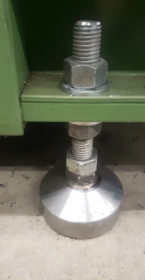
I made these for my emco. Theres a hockey puck inside each one. Piece of 3.5" ish pipe bored to fit the puck tightly, capped with 5/8" plate, tapered a bit, drilled and tapped the plate 3/4" so i could thread in a piece of 3/4" all-thread with a jam nut. Tightened up the jamb nut to lock the all-thread and welded the jamb nut to the plate. The puck is what they sit on and extends past the tube maybe 0.100" or so. Took a couple hours to make all 4 and cost maybe 20 bucks.
Yes, plasma'd them round, larger than the pipe, beveled the end of the 1"ish long pipe for welding, chucked them up by the pipe after welding and turned the plate round and faced/tapered/drilled tapped
after the studs were installed i chucked by the stud and hit them with emery
btw, they are all more or less the same size, dunno why the pic makes the right one look larger in diameter.
after the studs were installed i chucked by the stud and hit them with emery
btw, they are all more or less the same size, dunno why the pic makes the right one look larger in diameter.
Attachments
Last edited:
Theres a hockey puck inside each one.
Very nice Darren! Are the pucks bolted in too or just sitting in there?
I never used any damping on my lathe or mill. My instincts say that a hockey puck like you used is the right durometer for good damping. Feels about like an engine mount or jounce bumper. Same order of magnitude mass. But I have no real idea of what is best.
You happy with the damping on yours?
Wonder if anyone ever did some testing to see what is optimum, or how much it really even matters.....
Btw, those are beautiful Darren. Very nice job. Only a few hours eh! I'd need 8 of them for my lathe so it would prolly take me a week to make them!
Very nice Darren! Are the pucks bolted in too or just sitting in there?
Slightly press fitted
I never used any damping on my lathe or mill. My instincts say that a hockey puck like you used is the right durometer for good damping. Feels about like an engine mount or jounce bumper. Same order of magnitude mass. But I have no real idea of what is best.
You happy with the damping on yours?
Mostly used them for conformity to the concrete floor, and for grip. Not sure how much dampening they are really doing. There certainly isn't any vibration.
Wonder if anyone ever did some testing to see what is optimum, or how much it really even matters.....
Btw, those are beautiful Darren. Very nice job. Only a few hours eh! I'd need 8 of them for my lathe so it would prolly take me a week to make them!
Thanks. they are starting to rust a bit now. I should have blackened them before pressing the pucks in.
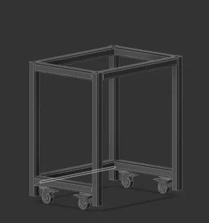
Revised the design to use 2x2-3/16" tubing and made it wider for stability and to accommodate a 26" tool chest from Homedepot. The legs will have levelling feet to raise the stand. I'm not sure if the casters will behave fine if they aren't able to rotate 360deg. Opinions?

Attachments
Last edited:
I'm not sure if the casters will behave fine if they aren't able to rotate 360deg. Opinions?
Looking great!
I typically use rotating castors on one end - usually the front, but sometimes one of the sides. That way you can steer it into place like parking a trailer.
Your levelling location looks good, but those casters are quite a bit inboard. That will make it easier to tip it while you push it around - which is exactly the time you want to avoid. I'd prefer to see them mounted on the back and front instead of the sides. Better yet, sticking out at the back and front but removeable at the front.
That's exact why it's good to brainstorm ideas! Brilliant, if I put them on the front and back support beams I can also have them rotate 360 for better maneuverability! the two support beams on the top plate will really be the attachement points of the mill base so I guess as long as the wheels are further out than that and the mill is centered/balanced it should be safer to move. I'll also add 1" steel angles to act as shelves to host my 26" Husky tool chest so this should also lower the center of gravity and add more rigidity.. I'd prefer to see them mounted on the back and front instead of the sides. Better yet, sticking out at the back and front but removeable at the front.
Modified design based on @Susquatch 's suggestion. I'm planning to weld the whole thing(casters will be bolted to a 3X3-1/8" plate welded to the bottom cross beams). Do you think that welding the two shorter sides as well as welding the top frame assembly and bolting them together using 3" angles through the 2x2s is a good idea? Just thinking this would minimize rework in case I want to make the stand wider or add other things to it...

historicalarms
Ultra Member
juwst got to this thread so a might late to the conversation but it looks like you have a handle on strength of your frame to me....but i have a concern over one of your statements & the frame design. You stated that you will be bolting the mill drill base directly to the outside frame rails, that would, in conjunction with your design photo that your frame is way too narrow for machine stability.
When I bought my mill drill from House of Tools in Edmonton the warehouse-repair shop manager was emphatic when I left the building with my machine , "build your bench twice as wide as you think you need...99% of the mill drills I have to repair are from falling over from weight unbalance.
After using my mill for 20 yrs for a multitude of jobs with varying sizes & weights I am super glad I took his advise. believe me there is a considerable change in center of gravity to the machine if you turn the head 90 deg to center and then move a loaded table to the same side full extension.
I am being just as emphatic as that warehouse mgr. when I say your leg feet MUST be out farther than the max extension of your table.
and dont forget that with these round column mills it is somewhat possible to mill extremely large parts that wouldnt fit on the table by rotating the head 180 deg and positioning your part from the floor or a table so the quil can reach your job.
I'm very tight on space front to back but have almost the same width on the stand and my table width. I also used the width and depth dimensions of the stand that the manufacturer makes but made everything a bit bigger because I'm unable to bolt the stand to my concrete floor. For reference my foot print is W 31" D 22", the stand sold by LMS is 14" W and 21"DYou stated that you will be bolting the mill drill base directly to the outside frame rails, that would, in conjunction with your design photo that your frame is way too narrow for machine stability.
The corner plates will re-inforce the tube frame and retain squareness.I'm very tight on space front to back but have almost the same width on the stand and my table width. I also used the width and depth dimensions of the stand that the manufacturer makes but made everything a bit bigger because I'm unable to bolt the stand to my concrete floor. For reference my foot print is W 31" D 22", the stand sold by LMS is 14" W and 21"D
Make the stand as wide as you can.
The arrangement will be TOP heavy and if you do something to TIP it one way or another, it will be dumped on its side. If you cannot make the base wider then fasten it to a post (or wall) with a strong bracket. If the stand cannot be shifted due to being tied to a stable room element, you can keep it narrow. Just make sure you can use the full travel of the table X&Y.
It is also a good idea to have some room all-around the mill in case you need to access the back of the Mill Column for adjustments.
Modified design based on @Susquatch 's suggestion. I'm planning to weld the whole thing(casters will be bolted to a 3X3-1/8" plate welded to the bottom cross beams).
Looking much better. I'd prolly lose those two top center bars. They add virtually nothing to the Design - especially given that you plan to have a 1/2 inch plate across the whole top.
So this is the idea with 4" steel angle, thoughts?
I think corner gussets like that are almost always a good idea if you don't mind doing it.
In principle, I totally agree with @historicalarms. I'm just not sure I would actually have a cart wider than my full bed extension. Practically speaking, something really heavy is also really big and would not be a point load on the far limit of bed travel. It's just that it's so hard to anticipate what those loads might be so the advice he gives is the fail safe approach.
The way to accomplish that without making your table unwieldy is to extend the legs out further on each side and turn the resulting bottom platform into a base tray for other equipment. It's either that or make a really wide stand both top and bottom and put essential milling tools on the two sides. (Let no surface exist without purpose is my motto!) stuff like the draw bar wrench, vise wrench, assorted Allen keys, brush and dust pan, oil cans, can of wind, note pad & pen/pencil, etc. As far as I am concerned these are all a part of the mill and should stay right there beside it anyway!
Are you saying to make the legs tapered to the outside? kind of like how smallish bandsaw stands are constructed?The way to accomplish that without making your table unwieldy is to extend the legs out further on each side and turn the resulting bottom platform into a base tray for other equipment
I droped that idea very quickly when I got a quote for the price of the plated prolly lose those two top center bars. They add virtually nothing to the Design - especially given that you plan to have a 1/2 inch plate across the whole top.
 for now I'm putting 3/4" MDF or plywood and eventually will be making a sheet metal tray for chips and coolant. This is why I added the two bars basically to drill holes through and attach the mill base through them
That's what I was getting at with my post #12. My prior RF-45 was very top heavy (high center of mass) assembly. It had the crappy sheet metal stand. although they may have improved it since my vintage. You can see in pic that the base perimeter is wider than the projected footprint under the mill casting. Guys like @Dabbler can provide much better guidance about moving the machine into position, especially tight space issues, but typically the head is retracted low to the table to lower COG. I cant remember if additionally angling the head is a good thing (getting mass lower yet) or a bad thing (now unbalance L/R because of extended motor weight). I'm just trying to say the stand is not just about statically supporting the mill weight. Anyways, the amateur moving day horror story goes something like: moving assembly into position, castor or leg or whatever gets dragged just a bit on floor, helper buddy is pushing ever so slightly on side of mill, mill does rollover. Some guys use hoist mill & spot onto (pre-placed) stand but that has pros & cons too depending on your situationYou stated that you will be bolting the mill drill base directly to the outside frame rails, that would, in conjunction with your design photo that your frame is way too narrow for machine stability.
Modified the design to be part welded for the sides and top and part bolted. I plan to use M8 bolts and nuts because I have a lot from a recent project. I also increased the static load to 4000N(900lb-f) to account for material and vise weights and have a healthy safety margin. M8 Bolts are torqued to 80% of maximum for grade 8.8 bolts(I actually have grade 12.9) again to simualate the worst case scenario. Other than balance front to back, I think that putting a tool chest in the bottom which is the plan, will lower the center of gravity (tool chest is about 80lbs) enough to minimize risk of tipping. Worst case if this doesn't work, I can make a tray and pour some concrete in the bottom, but looking at the designs of other benches carrying a similar sized mill, I believe(and really hope) it will be alright. For reference here's an example of an extension work bench carrying a similar sized mill:
 blondihacks.com

Furiosa’s Annex – Blondihacks
Last edited:
all very valid points but I guess without knowing the dimensions it hard to understand that the stand is actually as wide as the mill's table (30" or so), the mill base will be centered on the two middle cross bars on the top section of the stand. I didn't want to make it too wide because I wanted the weight of the mill to translate down through the legs and minimize sag. So I'm definitely much wider than the sheet metal stand(more than double) but where the design struggles is the depth which is only 2" deeper than the base of the mill.That's what I was getting at with my post #12. My prior RF-45 was very top heavy (high center of mass) assembly. It had the crappy sheet metal stand. although they may have improved it since my vintage. You can see in pic that the base perimeter is wider than the projected footprint under the mill casting. Guys like @Dabbler can provide much better guidance about moving the machine into position, especially tight space issues, but typically the head is retracted low to the table to lower COG. I cant remember if additionally angling the head is a good thing (getting mass lower yet) or a bad thing (now unbalance L/R because of extended motor weight). I'm just trying to say the stand is not just about statically supporting the mill weight. Anyways, the amateur moving day horror story goes something like: moving assembly into position, castor or leg or whatever gets dragged just a bit on floor, helper buddy is pushing ever so slightly on side of mill, mill does rollover.
View attachment 28591View attachment 28598
To illustrate why I didn't want to go much wider see below displacement simulation: