-
Scam Alert. Members are reminded to NOT send money to buy anything. Don't buy things remote and have it shipped - go get it yourself, pay in person, and take your equipment with you. Scammers have burned people on this forum. Urgency, secrecy, excuses, selling for friend, newish members, FUD, are RED FLAGS. A video conference call is not adequate assurance. Face to face interactions are required. Please report suspicions to the forum admins. Stay Safe - anyone can get scammed.
-
Several Regions have held meetups already, but others are being planned or are evaluating the interest. The Calgary Area Meetup is set for Saturday July 12th at 10am. The signup thread is here! Arbutus has also explored interest in a Fraser Valley meetup but it seems members either missed his thread or had other plans. Let him know if you are interested in a meetup later in the year by posting here! Slowpoke is trying to pull together an Ottawa area meetup later this summer. No date has been selected yet, so let him know if you are interested here! We are not aware of any other meetups being planned this year. If you are interested in doing something in your area, let everyone know and make it happen! Meetups are a great way to make new machining friends and get hands on help in your area. Don’t be shy, sign up and come, or plan your own meetup!
You are using an out of date browser. It may not display this or other websites correctly.
You should upgrade or use an alternative browser.
You should upgrade or use an alternative browser.
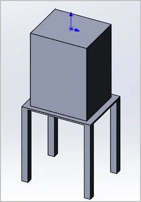
Mill Stand Design - Static Stress
- Thread starter Eyecon
- Start date

Just sharing this for fun more than anything...
Is that really how your loads will be applied?
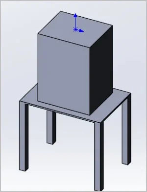
Is the mill a perfect fit on the top?
Is the mill base cast iron with low deformability vs the tubing?
I'd bet it is, so you should only have 4 corner loads and nothing in the middle.
In other words prolly even more over designed than your result..... LOL!
Will Fusion 360 do dynamic analysis too?
Just for poop and giggles, you should try changing material specs and dimensions.
TorontoBuilder
Sapientia et Doctrina Stabilitas
I know I dont know enough to apply the simulations to obtain reliable results yet... but I like that if I start this I can count on critical feedback from some smart people...Is that really how your loads will be applied?
Is the mill a perfect fit on the top?
Is the mill base cast iron with low deformability vs the tubing?
I'd bet it is, so you should only have 4 corner loads and nothing in the middle.
In other words prolly even more over designed than your result..... LOL!
Will Fusion 360 do dynamic analysis too?
Just for poop and giggles, you should try changing material specs and dimensions.
Gearhead88
Ultra Member
And then , there is , the bush league approach , kind of a , visit the lumber yard , bring home some timber . buck it up and bolt together the mother of all stands for a mill drill.
Years ago a buddy of mine , whom I've been friends with for 50 years calls and says " I want this monstrosity out of my garage , come and get it " . He got it for free , it had been taking up too much space in his already crowded garage and wanted it gone . So I helped him out and removed it for him. It came to my place without me having a spot planned out and for a short time it was taking up too much space in my garage too . This thing was built out of 2" x 8" 's , 4" x 4" 's , 3/4" plywood , it had eight legs and about three dozen carriage bolts , a lot of wood and waaaay over built for what it needed to do.

It didn't take long for me to realize , this thing was not suited for my shop , It went outside for a while , as yard art ............ then .....

I still have the machine , since ditching the " hand crafted " wood stand it has lived quite happily on a Busy Bee store bought mill/drill stand . With todays steel prices you'd be hard pressed to build a stand for the same cost of a store bought version .

I'm going to be building a stand / work center , for my valve grinding equipment soon , it will be steel tubing , it will have storage below and a roll out tray for the Sioux seat grinding kit . There isn't a commercially available stand that is perfectly suited to my needs , this is how I can justify a custom built stand / work center.
As with everything I build , it starts with an idea , a sketch (maybe) and I get to work , I already know what it is going to look like . .
Years ago a buddy of mine , whom I've been friends with for 50 years calls and says " I want this monstrosity out of my garage , come and get it " . He got it for free , it had been taking up too much space in his already crowded garage and wanted it gone . So I helped him out and removed it for him. It came to my place without me having a spot planned out and for a short time it was taking up too much space in my garage too . This thing was built out of 2" x 8" 's , 4" x 4" 's , 3/4" plywood , it had eight legs and about three dozen carriage bolts , a lot of wood and waaaay over built for what it needed to do.
It didn't take long for me to realize , this thing was not suited for my shop , It went outside for a while , as yard art ............ then .....
I still have the machine , since ditching the " hand crafted " wood stand it has lived quite happily on a Busy Bee store bought mill/drill stand . With todays steel prices you'd be hard pressed to build a stand for the same cost of a store bought version .
I'm going to be building a stand / work center , for my valve grinding equipment soon , it will be steel tubing , it will have storage below and a roll out tray for the Sioux seat grinding kit . There isn't a commercially available stand that is perfectly suited to my needs , this is how I can justify a custom built stand / work center.
As with everything I build , it starts with an idea , a sketch (maybe) and I get to work , I already know what it is going to look like . .
Last edited:
Personally I'm interested in this kind of thing. I think its untapped potential of CAD programs. Yes I know, garbage in, garbage out, dangerous in the wrong hands etc. But at least its a starting point.
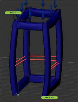
Is the color shading legend showing calculated (safety factor) multiplier based on max stress of material you have specified? ie 8.93 = blue, red would be 16? Can it provide deflection?
Is the color shading legend showing calculated (safety factor) multiplier based on max stress of material you have specified? ie 8.93 = blue, red would be 16? Can it provide deflection?
TorontoBuilder
Sapientia et Doctrina Stabilitas
I know, I was just saying I lack the skill set to make the best use of it yet..Personally I'm interested in this kind of thing. I think its untapped potential of CAD programs. Yes I know, garbage in, garbage out, dangerous in the wrong hands etc. But at least its a starting point.
Is the color shading legend showing calculated (safety factor) multiplier based on max stress of material you have specified? ie 8.93 = blue, red would be 16? Can it provide deflection?
fusion education is an evolving thing for me
I know I dont know enough to apply the simulations to obtain reliable results yet... but I like that if I start this I can count on critical feedback from some smart people...
As I'm sure you already know, experience is everything. WAAAY better than education.
In industry we used an iterative approach to stress and function analysis. First you model the part and do your analysis with best guesses based mostly on experience. Then you make a prototype and test it. Then you change the model parameters till the model gets the same results as the real world tests. Then more model changes to get closer to the Design goals, then more testing, and more modelling revisions. At some point you have to go with it. But using this method you can use your models to test thousands of different scenarios to optimize the results and address issues with just a few costly prototypes. When it's all done, you do confirmation tests on production parts. Then you wait till the customer proves you got it all wrong......
This would be a good approach for a ‘low volume’ support stand.As I'm sure you already know, experience is everything. WAAAY better than education.
In industry we used an iterative approach to stress and function analysis. First you model the part and do your analysis with best guesses based mostly on experience. Then you make a prototype and test it. Then you change the model parameters till the model gets the same results as the real world tests. Then more model changes to get closer to the Design goals, then more testing, and more modelling revisions. At some point you have to go with it. But using this method you can use your models to test thousands of different scenarios to optimize the results and address issues with just a few costly prototypes. When it's all done, you do confirmation tests on production parts. Then you wait till the customer proves you got it all wrong......
You’re not building an airplane, so beef it up a little, the forces on your stand are not going to be directly down (Side forces can come from torque on the vise bolts).
You also want the stand to be stable if you move the table to the extents of travel.
A heavy work piece can test the anchor bolts you have into the floor.
You can sketch up a lot of ideas in CAD.
but the real challenge is predicting ‘Worst Case Scenerios’. That is when experience comes in handy to apply all the ‘possible’ forces that may stress your fabricated stand.
The loads will be applied evenly to the top surfaces of the stand because I’m putting a 1/2” steel plate on top. Obviously the deformations are exaggerated (the max less than .001”) and the weight distribution is not necessarily even because of the column of the mill.Is that really how your loads will be applied?
The loads will be applied evenly to the top surfaces of the stand because I’m putting a 1/2” steel plate on top. Obviously the deformations are exaggerated (the max less than .001”) and the weight distribution is not necessarily even because of the column of the mill.
1/2" steel plate eh..... Woah!
I'm actually on the same page as @LenVW. I was just sharing how industry would do it cuz @TorontoBuilder was wondering about the process.
In addition to the balance (tipping factors) and bolt torque that Len mentions, it's also good to think torsional momentum - what would happen if the spindle grabs?
1/2" plate eh...... Ya, no worries about underdesigned....
My replacement work tables seem to have escaped construction yet another year unless Santa delivers a TIG, but I was curious about this kind of thing. We intuitively know there should be some perimeter bracing like red lines to box in the legs. And they usually serve secondary duty for shelve support. Your peripheral brace is along the base area, maybe for another purpose? Anyways, it would be interesting to see how the basic frame would look at 1.5, 2.0, 2.5" section. I've seen some nice work tables that look to be basically 'posts' with welded flanges top & bottom. Upper flange screws to table top, lower flange tap for a levelling foot or whatever. So maybe applying some lateral force parallel with table top would also be interesting. Sorry for the tangent, I know you are talking about a machine stand here.
Attachments
I've been out of school too long. Is there a parameter we that can indicate 'lateral stability'? (example pics skinny stand vs wider stand). CAD easily can spit out center of mass & moment of inertia of machine + stand assembly once we fudge weights. Then what's the next step?
Attachments
We intuitively know there should be some perimeter bracing like red lines to box in the legs.
I don't intuitively know that Peter. Other than for long spindly legs that buckle or fold, I doubt such braces do much good at all. Unless there are none at the bottom in which case they do provide a benefit but not as much as bottom braces would.
I think they do the most good at the bottom and provide reduced value as you move them up the structure.
The best isn't lateral braces at all. It's corner to opposite corner braces. Think scaffolding.
All valid points, safety factor is what I wanted to check because I wasn’t sure if 1/8” tubing would be sufficient to handle the weight. I still need to add support beams down below to prevent tipping as I do not intend on bolting the stand down for now.1/2" steel plate eh..... Woah!
I'm actually on the same page as @LenVW. I was just sharing how industry would do it cuz @TorontoBuilder was wondering about the process.
In addition to the balance (tipping factors) and bolt torque that Len mentions, it's also good to think torsional momentum - what would happen if the spindle grabs?
1/2" plate eh...... Ya, no worries about underdesigned....
I think you are right.Other than for long spindly legs that buckle or fold, I doubt such braces do much good at all. Unless there are none at the bottom in which case they do provide a benefit but not as much as bottom braces would.
As I continue fine tuning this design, I wonder if anyone knows where I can source machine leveling feet? The stuff I can find on Amazon seems very flimsy. I initially wanted leveling casters but now that I got a 1 ton shop crane I just want to be able to level the stand as my garage floor is heavily sloped.
TorontoBuilder
Sapientia et Doctrina Stabilitas
I make my own.As I continue fine tuning this design, I wonder if anyone knows where I can source machine leveling feet? The stuff I can find on Amazon seems very flimsy. I initially wanted leveling casters but now that I got a 1 ton shop crane I just want to be able to level the stand as my garage floor is heavily sloped.
But I'd suggest that you can design a caster & leveling foot mount combination. @SomeGuy had a removable caster on his lathe stand you should see if he will share some pics to give you ideas. I like an El mounted to side of post, and caster to the post. Then you can mount an acme screw thru the El to raise the stand off the casters and level whatever you have on your stand. Then is you need to move you screw the heavy screw up which lowers the stand onto the casters for easy moving
I wonder if anyone knows where I can source machine leveling feet?
You can make your own as @TorontoBuilder suggests or you can get a set of these. They are available in stud or plate versions. These ones are 4400 pounds - hardly flimsy..... LOL
VEVOR Heavy Duty Leveling Caster Set, 4 – Pack 2.5'' Self Leveling Casters, 4400LBS Max Loading Capacity, 1.2'' x 1.38'' Machine Casters Stem, for Moving Industry Equipment, Workbench, Shelves, White : Amazon.ca: Tools & Home Improvement
VEVOR Heavy Duty Leveling Caster Set, 4 – Pack 2.5'' Self Leveling Casters, 4400LBS Max Loading Capacity, 1.2'' x 1.38'' Machine Casters Stem, for Moving Industry Equipment, Workbench, Shelves, White : Amazon.ca: Tools & Home Improvement
a.co
I also like these that can be Bolted to the outside of your frame for extra stability. Again 4000 pounds.
If you search "machine leveling" on amazon, there are millions of choices all plenty strong enough.
On the issue of overhead crane vs wheels, I strongly recommend removable or liftable wheels. A crane isn't always convenient to use. I have one, and I like it. But nothing beats my loader tractor or a set of wheels!
TorontoBuilder
Sapientia et Doctrina Stabilitas
The last one is sort of like the style I was saying to make, but beefier.You can make your own as @TorontoBuilder suggests or you can get a set of these. They are available in stud or plate versions. These ones are 4400 pounds - hardly flimsy..... LOL
VEVOR Heavy Duty Leveling Caster Set, 4 – Pack 2.5'' Self Leveling Casters, 4400LBS Max Loading Capacity, 1.2'' x 1.38'' Machine Casters Stem, for Moving Industry Equipment, Workbench, Shelves, White : Amazon.ca: Tools & Home Improvement
VEVOR Heavy Duty Leveling Caster Set, 4 – Pack 2.5'' Self Leveling Casters, 4400LBS Max Loading Capacity, 1.2'' x 1.38'' Machine Casters Stem, for Moving Industry Equipment, Workbench, Shelves, White : Amazon.ca: Tools & Home Improvementa.co
I also like these that can be Bolted to the outside of your frame for extra stability. Again 4000 pounds.
If you search "machine leveling" on amazon, there are millions of choices all plenty strong enough.
On the issue of overhead crane vs wheels, I strongly recommend removable or liftable wheels. A crane isn't always convenient to use. I have one, and I like it. But nothing beats my loader tractor or a set of wheels!
The first ones are okay for a basement. I used them on a work bench, but they dont level well especially if you use them in a garage where they slope require by code if too high
Yes exactly why I scraped the wheels idea. I’ll eventually put proper caster but just to get up and running with the mill I wanted to simplify the build. I don’t trust my welding skills yet so I wanted to make something a little fool proof as well.I used them on a work bench, but they dont level well especially if you use them in a garage where they slope require by code if too high