-
Scam Alert. Members are reminded to NOT send money to buy anything. Don't buy things remote and have it shipped - go get it yourself, pay in person, and take your equipment with you. Scammers have burned people on this forum. Urgency, secrecy, excuses, selling for friend, newish members, FUD, are RED FLAGS. A video conference call is not adequate assurance. Face to face interactions are required. Please report suspicions to the forum admins. Stay Safe - anyone can get scammed.
-
Several Regions have held meetups already, but others are being planned or are evaluating the interest. The Calgary Area Meetup is set for Saturday July 12th at 10am. The signup thread is here! Arbutus has also explored interest in a Fraser Valley meetup but it seems members either missed his thread or had other plans. Let him know if you are interested in a meetup later in the year by posting here! Slowpoke is trying to pull together an Ottawa area meetup later this summer. No date has been selected yet, so let him know if you are interested here! We are not aware of any other meetups being planned this year. If you are interested in doing something in your area, let everyone know and make it happen! Meetups are a great way to make new machining friends and get hands on help in your area. Don’t be shy, sign up and come, or plan your own meetup!
You are using an out of date browser. It may not display this or other websites correctly.
You should upgrade or use an alternative browser.
You should upgrade or use an alternative browser.
Tips/Techniques Mill hold downs
- Thread starter Johnwa
- Start date
Tips/Techniques
I'm not sure I follow what you mean by 'T slot tear-out'? Are you saying that because the work is free to break free if necessary, it won't damage to table?
Presumably this type of clamp works by making a slip critical connection between the 'base' and the table via t nut - that's a connection tighter than the friction angle - and then using the screws to force the sliding blocks into the work. Those blocks clamp low down on the material - hence the 'toe' designation?
Presumably this type of clamp works by making a slip critical connection between the 'base' and the table via t nut - that's a connection tighter than the friction angle - and then using the screws to force the sliding blocks into the work. Those blocks clamp low down on the material - hence the 'toe' designation?
I'm not sure I follow what you mean by 'T slot tear-out'? Are you saying that because the work is free to break free if necessary, it won't damage to table?
It's difficult to describe but easy once you understand it.
Most tables and their slots are made of cast iron which is strong in compression and weak in tension. A bolt threaded into a T-Nut is easily capable of failing the T-slot in tension. To secure it properly, the T-Nut bolt must apply compression to both sides of the slot.
This is a very common mistake that new machinists make. The result is T-Slot tear out. The same thing can happen with through threaded T-Nuts and long bolts. That's why most T-Nuts are not threaded all the way through
If that isn't clear, I'll draw something for you tomorrow.
Your description of the toe function fits with my understanding too.
Dan Dubeau
Ultra Member
Clamps like that are great for facing plate. Always wanted to build some, but the shop next door at work has a bunch and I sneak over and borrow them once in a while whenever I need them. Which isn't very much.
Great idea. Thanks for sharing. Now on my to do list.Cool video, no loud music just the sweet sound of milling and drilling!
I fear tear-out.
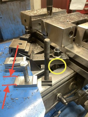
In this pic with typical T nuts the cast iron is in tension (yellow circle) as Susq explained and can cause tear-out.
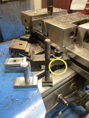
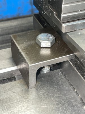
To the left is my modified T nuts and L clamps. Below pic is a closeup of this vise clamp.
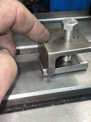
Here’s holding the vise. They are only used for this vise and have no height adjustment- also the bolts are cut to length to avoid up-lift.
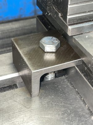
With the correct name - a quick google search shows several variationsThey are “toe clamps

Precision Fixturing and Toe Clamp Set – Bantam Tools
Found on Google from support.bantamtools.com
www.google.com
If I might be permitted.....
@CWret 's description leaves out a very important part of the function of these hold downs of his that may not be obvious to other readers.
Note that his custom T-Nut has tabs at both ends that bear against the bottom of the T-slot. At one end these raised sections bear against the bottom of his top bracket, and at the other end it bears against the bottom of the vise. In both cases, the combination places the two ends in compression against the T-slot which eliminates the chance of tear-out. Without these raised ears, his T-Nut could deform and place the center of the T-slot where the bolt is, in tension, which could result in tearout of the T-Slot on his table.
It is also important to note that while a longer T-Nut helps to spread the load and reduce the chances, it doesn't eliminate the possibility the way that the raised tabs directly under the components on top of the slots do.
Kudos to @CWret for a very elegant safe design.
Congratulations to all those who don't do this and have gotten away with it. However, it's not a practice that I could recommend. I can't imagine how it might feel to tear a chuck out of my mill table T-Slots needlessly.
Okay, so 'T-slot tear out' means damage to the table. Literally tearing out chunks of the table that are over stressed. That stress could be the result of pre-stress (over tightened bolts) or dynamic loadIt's difficult to describe but easy once you understand it.
Most tables and their slots are made of cast iron which is strong in compression and weak in tension. A bolt threaded into a T-Nut is easily capable of failing the T-slot in tension. To secure it properly, the T-Nut bolt must apply compression to both sides of the slot.
This is a very common mistake that new machinists make. The result is T-Slot tear out. The same thing can happen with through threaded T-Nuts and long bolts. That's why most T-Nuts are not threaded all the way through
If that isn't clear, I'll draw something for you tomorrow.
Your description of the toe function fits with my understanding too.
As I am sure Susquatch and others know already, there is a lot of stuff being skipped in this analysis.If I might be permitted.....
@CWret 's description leaves out a very important part of the function of these hold downs of his that may not be obvious to other readers.
Note that his custom T-Nut has tabs at both ends that bear against the bottom of the T-slot. At one end these raised sections bear against the bottom of his top bracket, and at the other end it bears against the bottom of the vise. In both cases, the combination places the two ends in compression against the T-slot which eliminates the chance of tear-out. Without these raised ears, his T-Nut could deform and place the center of the T-slot where the bolt is, in tension, which could result in tearout of the T-Slot on his table.
It is also important to note that while a longer T-Nut helps to spread the load and reduce the chances, it doesn't eliminate the possibility the way that the raised tabs directly under the components on top of the slots do.
Kudos to @CWret for a very elegant safe design.
Congratulations to all those who don't do this and have gotten away with it. However, it's not a practice that I could recommend. I can't imagine how it might feel to tear a chuck out of my mill table T-Slots needlessly.
Assuming elastic behaviour only
Every force in compression produces forces in tension at an angle. Generally, around 45 degrees. Think about using a tractor to grade a hill of dry sand. If it gets any steeper, the sand just slides sideways.
When a load is applied to a solid object, it spreads out in the same kind of way. Up down or sidesways, the load makes 'pyramids' from the source to the resistance. The exact shapes vary dramatically and depend to a great degree on the contact surfaces involved. Usually they are complex shapes where any sharp corner represents a stress concentration - AKA a stress riser - and a weak point
There is a lot more that it relevant about apparent load, moment length tributary area and failure modes, but I don't think I have ever considered any of these factors when bolting anything to my table

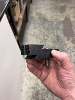
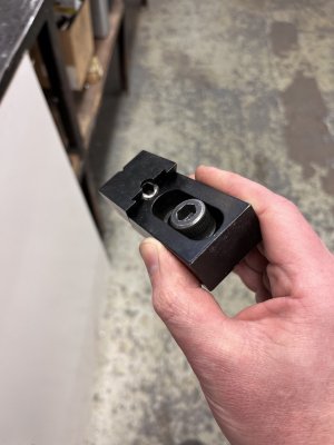
Table clamp
A table clamp I just finished from 1 1/4" x 1 1/4" CRS. The hardened jaw on the front of the clamp is missing.
 canadianhobbymetalworkers.com
As I am sure Susquatch and others know already, there is a lot of stuff being skipped in this analysis.
Assuming elastic behaviour only
Every force in compression produces forces in tension at an angle. Generally, around 45 degrees. Think about using a tractor to grade a hill of dry sand. If it gets any steeper, the sand just slides sideways.
When a load is applied to a solid object, it spreads out in the same kind of way. Up down or sidesways, the load makes 'pyramids' from the source to the resistance. The exact shapes vary dramatically and depend to a great degree on the contact surfaces involved. Usually they are complex shapes where any sharp corner represents a stress concentration - AKA a stress riser - and a weak point
Absolutely.
There is a lot more that it relevant about apparent load, moment length tributary area and failure modes, but I don't think I have ever considered any of these factors when bolting anything to my table
You obviously understand way better than most.
The three problems that raise their ugly head in this particular situation are:
1. The compressive strength of cast iron is about 5x its ultimate tensile strength.
2. Most steels have ultimate tensile strengths that are only slightly higher than their compressive strength.
2. There is this nasty stress riser on the inside upper outer corners of the Table T-slot.
By design, bolt threads are capable of developing extremely high tensile or compressive forces.
That is why most T-Nuts are not threaded all the way through. This prevents users from threading a long bolt through the nut and then loading the T-Slots to failure.
But the same thing can happen with T-slot bolts even if they don't reach to the bottom of the T-Slot. If the setup is such that the steel can deform within its elastic range but above the failure limit of the cast iron T-Slots, they can and do fail.
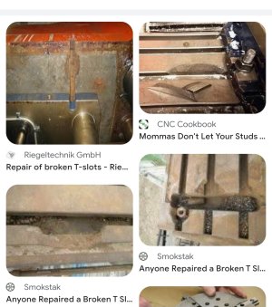
But even if I didn't know this, I have seen enough broken T-Slots in my time to know that it's a lot more common than most people realize. Here is a random screen shot of a Google search for "broken T-slot". Easy to see why I call it tear out. Very common.
My guess is that your knowledge of stress and strain has been your friend. Basically, you know that it doesn't take much torque on the bolts to develop extremely high friction between the parts and the table. So you don't over-tightened them and therefore you have never had a problem. That doesn't work for everyone. Far too many people over tighten those bolts and put their tables at risk.
Again, I've seen it far too many times and the reasons are always the same - a T-slot excessively loaded in tension.
That's why some guys say never buy threaded through T-Nuts and why I advocate only using T-Nuts and hold downs in compression. It's almost impossible to overload a clamp to the point where it can tear out a T-slot if it is fastened in compression.
I can appreciate that your experiences have been good for the reasons I suspected. If you can, I'd suggest you see if you can get your hands on a scrapped table. Then do some experiments. I think you will be surprised at how easy it is to pop a T-slot in tension and how impossible it is to pop one in compression - in most cases, the bolt will strip first simply because of the area difference.

