• Scam Alert. Members are reminded to NOT send money to buy anything. Don't buy things remote and have it shipped - go get it yourself, pay in person, and take your equipment with you. Scammers have burned people on this forum. Urgency, secrecy, excuses, selling for friend, newish members, FUD, are RED FLAGS. A video conference call is not adequate assurance. Face to face interactions are required. Please report suspicions to the forum admins. Stay Safe - anyone can get scammed.

measure over pin method for gears

Using the info from the video and your dimensions we would calculate DP this way.
(2 + tooth count) / OD in inches or
32/ 1.606" = 19.925

Could you post the OD of some of your other gears so we can check them as well?

I have been afraid of hearing that ever since I bought them. Using the tooth profile printouts, they did look close to 20DP. I had to hang upside down from an oak tree to decide and the rope broke. After that, 1.25 looked best. o_OSo that is what I ordered.

I'll measure a few more when I get back out to the shop. I'm supposed to be cleaning out my clothes closet according to SWMBO. Apparently it's the only room in the house that doesn't meet her standards. But she has gone to town and I'd rather count teeth on a thousand gears....... :rolleyes:
 
I watched this video from Evolvent Design that deals with measuring gears to determine if they are Module (metric) or Imperial (diametral pitch) (DP). He demonstrates how to measure an odd tooth gear. Since you can't directly measure the OD, instead, measure the distance from the inside of the bore to the tip of a tooth, multiply that dimension by 2 and add that number to the bore dimension.

Thanks, I saw that video too. Measuring the equivalent radius related segment vs diametrical over 2 pins would work fine if the gear was laying on the bench like his example. I guess the situation I was visualizing was machining the gear & confirming the actual measurement progression vs target dimensions. In this mode the shaft hole is probably less accessible, so easier to measure OD type parameters.
 

Attachments

  • 1707072831663.webp
    1707072831663.webp
    7.6 KB · Views: 0
Could you post the OD of some of your other gears so we can check them as well?

Here you go.

54 - 69.9
78 - 99.9
63 - 81.1
56 - 72.4
57 - 73.6

I would think the 30 would be the most relevant. But that's just a guess. Also, my teeth were "prolly" cut in Taiwan if that matters.
 
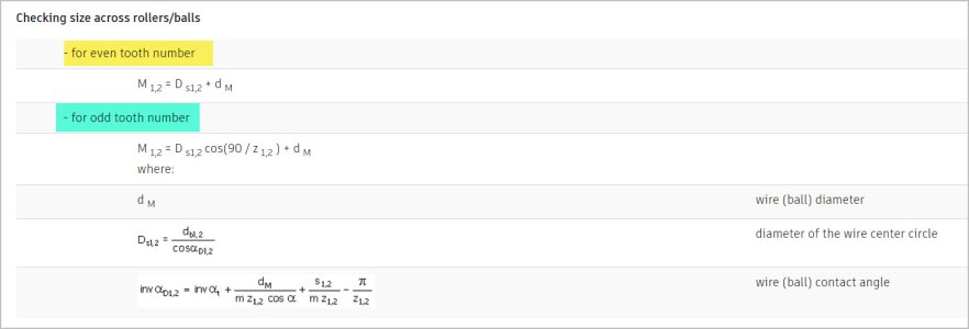
@lucsimoneau thanks for the workflow. I started a spreadsheet some time ago & these expressions look familiar. I noticed that wire diameter is a calculated parameter & then wire-to-wire diameter calculated from that. What is nice about this calculator tool is you can input a specific wire diameter (within dimensional limits) which is likely more practical of pins on hand. He then calculates the wire-to-wire on that basis but stops short of odd teeth. I'm sure there must be a solution just using formulas. I took a stab at it graphically but I'll play with the spreadsheet some more. Surprised this isn't a more common public domain tool.


Example if you leave the user defined pin diameter blank, it calculates presumably the recommended default of 1.7445mm. Don't have that kicking around, but I have a 2.0mm

1707073889648.webp

1707073797238.webp


1707073300383.webp
 
54 - 69.9
78 - 99.9
63 - 81.1
56 - 72.4
57 - 73.6

When I do the arithmetic using the DP formula all 5 of those gears work out to between 20.32 and 20.35. Using the Module formula they all work out to between 1.247 and 1.249. So with the numbers for those 5 gears it looks like Module 1.25 is closer than 20DP I think I would try cutting one gear using the Module 1.25 cutters you already have and see how it meshes with your existing gears.

Yahooo! I prolly didn't waste my coin after all!

Cut a test gear eh? ...... Duhhhhh. Why didn't I think of that? If I have (or can find) a piece of bar big enough, I'll do just that! Any old steel will do for a test. And gears are fun to cut. I'll get right on it even if I have to buy a little stock to do it with. Going to Windsor on Tuesday to pick up some bandsaw blades so I'll do it then if I don't have any already.
 
Getting warmer. Their formula terminology look different, I probably need to start at the top. But looks like odd tooth count distance can be calculated with pin diameter & teeth count as inputs. But no accompanying sketch - does this distance mean across tangents of 2 furthest possible teeth positions? Sheesh


Attachments

  • EDT-04-02-2024 8.21.33 PM.jpg
    EDT-04-02-2024 8.21.33 PM.jpg
    42.5 KB · Views: 1
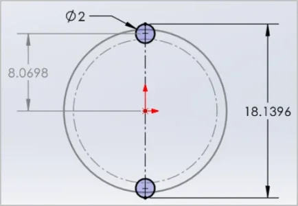
I think I missed an important detail from the evolventdesign calculator & my first CAD sketches are wrong. Point 7 says measure your gear across any pair of furthest apart teeth (closest to 180 deg). That step fully defines it. So I changed my (now unnecessary) CAD diagram to show what I think they mean. Its still a distance over the closest pin tangents, but its just at that slight angle dictated by placement of the odd tooth. My 15tooth hear has openings every 360/15=24 deg apart. So the position of closest pin would be like so, half of 24 deg = 12 deg. I'm now going to find or generate a solid model & see if this goes around using the 2mm sized pin tangent to the involute

1707104447068.png


1707104362850.png
 
Last edited:
Point 7 says measure your gear across any pair of furthest apart teeth (closest to 180 deg).

Just a thought. You sure they don't mean opposites for even numbers of teeth and two on one and one on the other (like using thread wires) for odd numbers?
 
Although im sure you can get cad drawings, I have a whole stack of 1.25 gears here in case you need a real life measurement.
 
Bingo. I overlaid 2mm wires into a download 15T mod-1 gear & calculated the center to center pin distance. It matches the evolventdesign calculator

View attachment 43714View attachment 43715View attachment 43716
Nice! It does seem counter intuitive to only use 2 pins on an odd tooth gear but even the Machinist Handbook shows that to be the correct method. Do you have a project in the works that will involve gear making Peter?
 
Back
Top