• Spring 2024 meetup in Calgary - date Saturday, April 20/2024. discussion Please RSVP Here to confirm and get your invitation and the location details. RSVP NOW so organizers can plan to get sufficient food etc. It's Tomorrow Saturday! you can still RSVP until I stop checking my phone tomorrow More info and agenda
  • We are having email/registration problems again. Diagnosis is underway. New users sorry if you are having trouble getting registered. We are exploring different options to get registered. Contact the forum via another member or on facebook if you're stuck. Update -> we think it is fixed. Let us know if not.
  • Spring meet up in Ontario, April 6/2024. NEW LOCATION See Post #31 Discussion AND THE NEW LOCATION

measure over pin method for gears

PeterT

Ultra Member
Premium Member
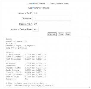
I found this website that calculates tooth depth of spur gears using user defined gage pins diameters making contact between 2 neighbor teeth as per their sketch. Useful for measuring an existing gear, or cutting a new gear because you could compare the actual distance vs the theoretical distance. But what about odd tooth gears where the valleys will not align vertically like the reference sketch? Unless I missed it, the website doesn't even mention this. Unless they factor the odd tooth into the calculation & its still a pin to pin measurement (which seems odd & very undefined).

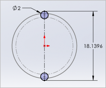
Assuming them mean theoretical vertical distance I made a mod-1, 15T gear, 20-deg PA to see if I could fake it. I transposed the resulting vertical distance of 18.1396 mm over 2 mm diameter pins, but then assume 2 pins within the bottom 2 teeth valleys 360 deg / 15T =24 deg apart, but at the same radius in order to still measure vertically at their outer tangents. Surely there must be a better way. Does anyone have experience with this? Is there a formula relationship to OD & PD maybe? Part of what makes this tricky *I think* is if the cutter profile is advancing into the blank X amount, its not like a cutting tool reducing OD by 2X because the cutter has an involute profile and that profile tangency to pin is what is driving the pin to pin measurement
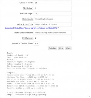

1707020100801.png 1707021117967.png 1707021256758.png
 

Attachments

  • 1707021079705.png
    1707021079705.png
    26.7 KB · Views: 2
  • SNAG-03-02-2024 8.35.30 PM.jpg
    SNAG-03-02-2024 8.35.30 PM.jpg
    129.9 KB · Views: 2
  • SNAG-03-02-2024 8.36.30 PM.jpg
    SNAG-03-02-2024 8.36.30 PM.jpg
    165.6 KB · Views: 2

RobinHood

Ultra Member
Premium Member
I have measured gears using the two pin method. It always seemed to work out.

I think unless one uses a CMM, the measuring axis of an odd toothed gear will be slightly off of the normal axis (as seen in your model and the following explanation). The measurement M compensates for that and it seems an accepted practice.


Peter, I like your CAD model and it clearly shows the issue.

I have not found where that is addressed. I wonder if the error is small enough that it can be “ignored” since gears need to have clearance to mesh with each other properly anyway. As long as the center distances are correct, it will work.

Perhaps another thing to consider: the smaller the Module and the higher the tooth count, the smaller the deviation will be.

Perhaps you can let CAD calculate the difference in your example?
 

John Conroy

member
Premium Member
I watched this video from Evolvent Design that deals with measuring gears to determine if they are Module (metric) or Imperial (diametral pitch) (DP). He demonstrates how to measure an odd tooth gear. Since you can't directly measure the OD, instead, measure the distance from the inside of the bore to the tip of a tooth, multiply that dimension by 2 and add that number to the bore dimension.


Susquatch

Ultra Member
Administrator
Moderator
Premium Member
Where were all you guys when I was trying to figure out what my gears were? I had to use a paper template for God sake. It was hopelessly ambiguous. Now I have to use this method - potentially to find out I bought the wrong cutter set......

What is really odd is that i used info from the Evolent website and never saw this. It is either newly added or I am blind. The latter is both true and likely.

I have bookmarked this thread.

@PeterT - I'd like to add a vote for you to do the CAD analysis of the difference per @RobinHood's request above.
 

Susquatch

Ultra Member
Administrator
Moderator
Premium Member
For what it's worth, look it up in the Machinery's Handbook - very well explained. If needed, I can go thru an example of the calculations and even the tolerances of mesurement:

What chapter / page is that? Does it include metric?

I must live in a cave...... I missed this too.

Yes, I'd love an example.
 

John Conroy

member
Premium Member
Where were all you guys when I was trying to figure out what my gears were? I had to use a paper template for God sake. It was hopelessly ambiguous. Now I have to use this method - potentially to find out I bought the wrong cutter set......

What is really odd is that i used info from the Evolent website and never saw this. It is either newly added or I am blind. The latter is both true and likely.

I have bookmarked this thread.

@PeterT - I'd like to add a vote for you to do the CAD analysis of the difference per @RobinHood's request above.
I actually posted a ink to the Evolvent Design video back in May when I was making change gears for my lathe. Post # 161

 
Last edited:

lucsimoneau

Active Member
OK, so here goes, using PeterT's example above: m=1.0 N=15T PA=20°:
1- Diametral Pitch (P) --> m = 25.4 / P P = 25.4/1.0 = 25.4
2- Pitch Diameter (D) --> D = N / P D = 15/25.4 = 0.59055"
3- Outside Diameter (OD) --> (N+2) / P OD = (15 + 2) / 25.4 = 0.6993"
4- Addendum (a) --> a = 1 / P a = 1 / 25.4 = 0.0394"
5- Dedendum (b) --> b = 1.250 / P b = 1.250 / 25.4 = 0.0492"
6- Circular Pitch (p) --> p = π x D / N p = π x 0.59055 / 15 = 0.1237"
7- Circular Thickness (t) --> t = p / 2 t = 0.1237 / 2 = 0.0618"
8- Wire diameter Øw --> 1.728 / P Øw = 1.728 / 25.4 = 0.068"
9- Overwire Diameter (M) --> 17.2871 / P M = 17.2871 / 25.4 = 0.6806" (value in formula obtained from MH)
1707064440458.png
 

Susquatch

Ultra Member
Administrator
Moderator
Premium Member
I actually posted a ink to the Evolvent Design video back in May when I was making change gears for my lathe. Post # 161

Yes, I remember that. I also remember your offer to send me a couple of slices of steel bar. I didn't remember any reference to a wire based measurement.

What I do remember is the tooth profile printouts to compare with and that's what I used to order the cutter set.

In the time between posting on @lucsimoneau 's reference to machinery Handbook I've been reading the handbook. It is not as useful as I thought cuz it looks like you need. The pressure angle to use it. That is useless when all you have is a gear with no info on it.

I do have a standard thread wire set, but I'm not sure they are the same as the Van Keuren standard that the handbook refers to and if they are, I still don't know the pressure angle with any certainty.

Surely this can be simpler than I am seeing here.
 

John Conroy

member
Premium Member
I also used the catalog pages from Madler as they give the dimensions for every gear. For instance I remember that your lathe has a 30 tooth gear in it's selection of change gears. If your 30 tooth gear has an OD of 40mm it is very likely a Module 1.25 gear as shown on this page form their catalog.


If your 30 tooth gear has an OD of 48mm it is very likely as Module 1.5 gear as seen on this page of the catalog.


I came up with 20 degree pressure angle because I couldn't find any listing for any other angle for Module 1.25 gears.
 

Susquatch

Ultra Member
Administrator
Moderator
Premium Member
Ok.
I also used the catalog pages from Madler as they give the dimensions for every gear. For instance I remember that your lathe has a 30 tooth gear in it's selection of change gears. If your 30 tooth gear has an OD of 40mm it is very likely a Module 1.25 gear as shown on this page form their catalog.


If your 30 tooth gear has an OD of 48mm it is very likely as Module 1.5 gear as seen on this page of the catalog.


I bought 1.25.

Lets see how I did.....

My 30 tooth has an OD of 1.606 across opposite teeth which is 40.82mm

A lot closer to 1.25 than 1.5. So far so good!
 

John Conroy

member
Premium Member
Using the info from the video and your dimensions we would calculate DP this way.
(2 + tooth count) / OD in inches or
32/ 1.606" = 19.925

We would calculate Module this way
OD in mm/ (2 + tooth count) or
40.82/32 = 1.275

Then using his chart to display whether it is likely Module or DP it almost looks like it is 20DP and not Module 1.25
screenshot_20230313-091819_youtube-jpg.34223


Could you post the OD of some of your other gears so we can check them as well?
 
Last edited:
Top