Little drill press

ducdon

Super User
Premium Member
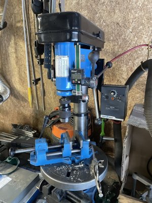
I have a 22 inch drill press but find it kinda large for some of my smaller projects. I use # size drills often. I was talking about getting something smaller. A friend kindly gifted me this 11 inch Canadian made Beaver for which I'm most thankful. I think it had been in storage for awhile and was pretty grungy, had some drill holes in the table and some surface rust. I stripped it down and gave it a good cleanup and fresh paint. Filled the unwanted holes. Some new spindle bearings, a keyless chuck and made a new down feed handle. I think it will work out well. Phase two of the project calls for variable speed. If I can find one, a 1/2 horse 3 phase motor with a VFD. Variable speed is some new territory for me so I'm open to comments from anyone who has experience?
PXL_20231129_162535705.jpg PXL_20231116_022912514.jpg PXL_20231129_161515560.jpg
PXL_20231129_161506997.jpg
 
Last edited:

Susquatch

Ultra Member
Administrator
Moderator
Premium Member
A friend kindly gifted me this 11 inch Canadian made Beaver for which I'm most thankful.

My Beaver is more like your modern 22! LOL!

Lots of guys on here can help with your VFD plans.

I suggest you start looking for the motor right away. If you can find one with the right shaft size and frame size you will be miles ahead. Best to start looking now.
 

jannickz

New Member
It's great to hear that you're getting good use out of your smaller drill press. Variable speed can be a very useful feature for drilling different materials and sizes of holes.
Make sure the motor you choose is compatible with the VFD. Not all motors are created equal, and you'll need to make sure the motor you choose is compatible with the VFD you're using.
 

CWret

Ultra Member
Premium Member
Very nice little drill press. I’ve had a couple of Beaver table saws. They were well built, solid and heavy.

I have a Japanese made 13” variable speed KIRA drill press. I cleaned it up and painted it. I can’t say I restored it because no repairs were required. It is a 4 speed via pulleys driven by a DC motor. The combination gives variable speed from 10 to 3,800 rpm. If you’d like more info on my KIRA do a Forum search for KIRA and CWret. Or have a look at my posts #15 & 21 in the thread “Keeping old outdated tools in the shop”
 

Attachments

  • 9731550E-7F27-4F9F-B8B0-C301684E7E8B.jpeg
    9731550E-7F27-4F9F-B8B0-C301684E7E8B.jpeg
    711.7 KB · Views: 7

Dabbler

ersatz engineer
I really love those Beaver drill presses. Nice get, and great restore! Call me about VFDS any time.
 

Alawishes

Member
The motor on my drill press croaked and that was my kick in the butt to install a DC motor. Available for free on treadmills that people are giving away. My incredibly good luck the frame just bolted on, shaft size right for my pulley hole, and even the right colour! AC voltage regulator and bridge rectifier off AliExpress for around $20. My motor was rated at 2.5 hp but I’m thinking that was RadioShack hp and probably only half that, but still lots more than the original 1/2 horse motor. The full speed of the DC motor is 4300 so I keep the belt on lowest speed range. Great to have the higher rpm’s for smaller drill bits — I think a 1/16” drill is supposed to run at 6k rpm. I still need to install a choke coil and ferrite ring to smooth out the DC voltage. I’d do the same mod in a heartbeat. I’m helping my buddy put a treadmill motor on his mill drill. We had to modify his motor frame and make a sleeve to match the larger pulley hole but he’s up and running now.
 

ducdon

Super User
Premium Member
The motor on my drill press croaked and that was my kick in the butt to install a DC motor. Available for free on treadmills that people are giving away. My incredibly good luck the frame just bolted on, shaft size right for my pulley hole, and even the right colour! AC voltage regulator and bridge rectifier off AliExpress for around $20. My motor was rated at 2.5 hp but I’m thinking that was RadioShack hp and probably only half that, but still lots more than the original 1/2 horse motor. The full speed of the DC motor is 4300 so I keep the belt on lowest speed range. Great to have the higher rpm’s for smaller drill bits — I think a 1/16” drill is supposed to run at 6k rpm. I still need to install a choke coil and ferrite ring to smooth out the DC voltage. I’d do the same mod in a heartbeat. I’m helping my buddy put a treadmill motor on his mill drill. We had to modify his motor frame and make a sleeve to match the larger pulley hole but he’s up and running now.
Any pictures? Most of the treadmill motors I see come with Flywheel and fan. What did you do with them?
 

Alawishes

Member
664F24DB-8189-4C9A-949D-47AA379AE5F0.jpeg F0611C75-41AE-40E7-9849-5525DF70EA44.jpeg I took the fan off and held that end of the armature in copper jaw covers in my vise. The big heavy flywheel just screws off and I ended up drilling into the motor shaft in 2 places to install 2 set screws, which actually transmit the torque from the motor shaft to the pulley. Fan back on. So far I’ve managed to drill a 1” hole in some thick steel, so great to be able to slow the drill down. I haven’t tried any big hole saws yet. I used a larger metal electrical box to house the AC regulator and bridge rectifier. Not enough space in the pulley area to install the pickup for a tach so I put in a 0-100 digital voltmeter, and as soon as a tiny power supply arrives I’ll hook that up. My logic is 90 volts DC is max for the motor so it should give me a rough idea of rpm, which I can check against my digital hand held tachometer. Maybe I’ll make a chart for x volts = y rpm, or maybe just continue winging it. The voltmeter will be lit when the power is on, so a reminder not to walk away from it.
 

Alawishes

Member
No link at the moment but check for AC voltage regulator 10,000 watt. I used a 4000w and changed to a larger one after it blew up. I used a 50 amp bridge rectifier but if I had it to do again I’d choose 100amp. I decided to use a metal electrical box to help with heat dissipation.
 

Tecnico

(Dave)
No link at the moment but check for AC voltage regulator 10,000 watt. I used a 4000w and changed to a larger one after it blew up. I used a 50 amp bridge rectifier but if I had it to do again I’d choose 100amp. I decided to use a metal electrical box to help with heat dissipation.
Those SCR dimmer/temperature/speed controls that Aliex offer have specs for 110/220V in, do they essentially allow you to control the output from 0 - 100% of the input voltage? Said differently, for 110VAC in we would expect something approaching 110VAC out?

After the rectifier bridge, a treadmill choke would clean up any/enough of the noise on the rectified DC?

Do the controllers have any sort of overload protection for things like a stalled motor?

Thanks!

D :cool:
 

Alawishes

Member
Dave, I’m not an expert here. I believe the AC voltage controller goes from 0-100% and it appears that way with my motor. There is a great series on YouTube by DazeCars, who really seems to know what he’s talking s about — very interesting demos. He says a choke coil and ferrite core ring really helps with smoothing the DC voltage. And he suggests a fuse protection in the circuit.
 

Dabbler

ersatz engineer
Those SCR dimmer/temperature/speed controls that Aliex offer have specs for 110/220V in, do they essentially allow you to control the output from 0 - 100% of the input voltage? Said differently, for 110VAC in we would expect something approaching 110VAC out?
SCR dimmers (Triac dimmers in the majority of cases since the 90s) are just a switch that delays turning on until the appropriate part of the waveform is reached. This has the effect of 'lowering' the voltage, but only at very low illumination levels. For the first half (the brightest half) the measured voltage will always be the full voltage.
For instance:

Dimmerl.JPG

A Lamp dimmer is just a switch that turns on every cycle with a delay. If you are at '80% brightness', at point A, the dimmer delays turning on, so the red part of the current is not delivered to the device, then it turns on, and it resets at the point that the voltage reaches zero volts again. this repeats every cycle. Your measured voltage, until point "B" will be the same - full voltage, even though the output is 50% 'dimmed'. Only when you reach "C", or about 20% brightness, that your measured voltage will be lower.

I hope this makes sense...

To actually control the output voltage (as you might imagine - from 100% to 0%) you need to use an autotransformer, but that has other side effects on the load....
 

Tecnico

(Dave)
@Alawishes , I’ve seen the Daze site/videos, lots of interesting info there. I think some of it is based on field experiments.

@Dabbler , thanks for your explanation, it kind of looks like it’s obtaining the energy under the curve/average voltage to do the driving. I presume that it does the same for the negative part of the sine wave and of course the bridge turns that into “DC”.

It looks like speed control of the DC motor would be approximate, depending on the load.

D :cool:
 

Dabbler

ersatz engineer
I presume that it does the same for the negative part of the sine wave

@Tecnico I tried to keep the explanation as simple as possible. Using an SCR does this for the half-wave, so you need 2 SCRs to do full wave, but the Triac is the AC version (it has 2 SCRs coupled internally)_ and then the effect happens for the full wave. That is, it is AC out on the dimmer circuit, so if you need DC, a bridge is added after the dimmer.

To control a DC motor, inexpensive PWM modules exist that will do the job very well.
 

Tecnico

(Dave)
@Tecnico I tried to keep the explanation as simple as possible. Using an SCR does this for the half-wave, so you need 2 SCRs to do full wave, but the Triac is the AC version (it has 2 SCRs coupled internally)_ and then the effect happens for the full wave. That is, it is AC out on the dimmer circuit, so if you need DC, a bridge is added after the dimmer.

To control a DC motor, inexpensive PWM modules exist that will do the job very well.

@Dabbler , got it on the triac! That’s what I was thinking of but I don’t have the electronic vocabulary to get into that level so keeping it simple is good!

WRT PWM modules, I have one of the simple Aliex ones which only puts out a PWM signal. The plan is to experiment with one of the treadmill power boards that accept a PWM signal. I’ve seen Daze’s take on that and recognize that it has some drawbacks because it bypasses the (equipment) safety systems built into the treadmill, he failed a board due to a locked rotor incident.

I presume you’re speaking of a board that has a PWM controlled power supply? Is that something available off the shelf economically?

On a similar theme and closer to the OP’s topic, I’m in the early stages of testing a conversion that uses both the treadmill power and control boards with the safeties intact. I’m planning to put it in my project thread.

This one was unique/primitive enough in that it used simple membrane switches to select the speed so I was able to mimic those and keep the safety systems. Thing is it appears that very few systems can be reconfigured that way so I’m keeping my eye out for alternatives so if there’s an economical power/PWM board out there I’m interested!

D :cool:
 

Dabbler

ersatz engineer
I'd just buy a commercial DC Motor control module that has the PWM built in. I think they aren't too expensive. Back in my day (rocking in his chair, smoking a pipe) we had to build it all up from scratch. I've never seen Daz's videos, but I'm leery about repurposing a board - If he gives goo instruction it could be a way to go....
 
If you are trying to smoothen your DC voltage coming off the bridge rectifier you need a couple of capacitors (big ones) to filter the voltage as there is still a ripple.

A couple of beads or coils is in a feedline is a choke, primarily for current and smooths the current flow. Helps get rid of noise in the line.
 

Alawishes

Member
If you are trying to smoothen your DC voltage coming off the bridge rectifier you need a couple of capacitors (big ones) to filter the voltage as there is still a ripple.

A couple of beads or coils is in a feedline is a choke, primarily for current and smooths the current flow. Helps get rid of noise in the line.
Degen, the caps sure make sense to help smooth out the voltage. I'd be willing to experiment with this.... do you have any idea of a rough place to start? I'd imagine there is some math involved here. I've seen one treadmill with the motor listed as 1.5hp, and it used a choke coil, that looked like a transformer except just 2 wires. There was one large cap on the control board, rated at 1000uf and the board was listed at 0-100vdc 15A continuous (30a peak). I've noticed the "2.5hp" motor on my drill press works fine at lower rpm but it vibrates a bunch until I set it at a higher rpm.... maybe caps and a choke coil will help out here.

Dabbler, thanks for the info on how Triacs work.-- very interesting. I've seen some University of YouTube videos on PWM's. Not that expensive but it seems they need to be hooked up to a controller board, and then there's the soft start issue. Suggestions? Thx, al.
 
Top