-
Scam Alert. Members are reminded to NOT send money to buy anything. Don't buy things remote and have it shipped - go get it yourself, pay in person, and take your equipment with you. Scammers have burned people on this forum. Urgency, secrecy, excuses, selling for friend, newish members, FUD, are RED FLAGS. A video conference call is not adequate assurance. Face to face interactions are required. Please report suspicions to the forum admins. Stay Safe - anyone can get scammed.
-
Several Regions have held meetups already, but others are being planned or are evaluating the interest. The Calgary Area Meetup is set for Saturday July 12th at 10am. The signup thread is here! Arbutus has also explored interest in a Fraser Valley meetup but it seems members either missed his thread or had other plans. Let him know if you are interested in a meetup later in the year by posting here! Slowpoke is trying to pull together an Ottawa area meetup later this summer. No date has been selected yet, so let him know if you are interested here! We are not aware of any other meetups being planned this year. If you are interested in doing something in your area, let everyone know and make it happen! Meetups are a great way to make new machining friends and get hands on help in your area. Don’t be shy, sign up and come, or plan your own meetup!
You are using an out of date browser. It may not display this or other websites correctly.
You should upgrade or use an alternative browser.
You should upgrade or use an alternative browser.
Line Noise Suppression Capacitor?
- Thread starter RobinHood
- Start date
You can also try solder wick it can get stubborn solder out, sometimes you have to reflood everything with solder a couple of times and then you get a better heat transfer and better chance of getting it all or enough out.
You have to be right that you were getting heat sinking on the board. Try the heated TIG rod thing.
Tin solder melts above 400F (but not much above - depending on brand, 420-440F I just used my iron at 750F and easily melted a blob on an ROHS board.
- probably adds confusion to the matter, however.
Tin solder melts above 400F (but not much above - depending on brand, 420-440F I just used my iron at 750F and easily melted a blob on an ROHS board.
- probably adds confusion to the matter, however.
Last edited:
Former Member
Guest
There is a special solder used to desolder that drops the solder temperature, I belive Sayal has some in stock otherwise Digikey, Mouser.ca or Amazon.
Desolder wicks and Desolder Vacs are the way to go.
I use only Leadfree, but it important to understand that not all lead free is equal. KOKI brand is the best hands down. Behaves like leaded if used correctly. Ideal temp range between 715-735C, I typically run 725C
Desolder wicks and Desolder Vacs are the way to go.
I use only Leadfree, but it important to understand that not all lead free is equal. KOKI brand is the best hands down. Behaves like leaded if used correctly. Ideal temp range between 715-735C, I typically run 725C
VicHobbyGuy
Ultra Member
Really? That is HOT.Ideal temp range between 715-735C, I typically run 725C
Former Member
Guest
Sorry F not C.Really? That is HOT.
I'm starting to run low on my Kester. Where do you get KOKI & what part number/composition?I use only Leadfree, but it important to understand that not all lead free is equal. KOKI brand is the best hands down. Behaves like leaded if used correctly. Ideal temp range between 715-735C, I typically run 725C
RobinHood
Ultra Member
Success!
I tried with a 0.070” HSS drill heated to red hot with a propane torch to melt the solder first thing this am. No joy.
Deckel GK12 pantograph to the rescue. I set the board up upside down on parallels to mill off the excess solder and the protruding component lead. This is a 9/64” three flute end mill, 8000 rpm.

If you look closely, you can see the center of the hole - it’s the copper of the component lead. (The circle is where I touched off and scored the coating of the board). Next I got a 70 thou carbide PCB drill and peck drilled it out. 20000 rpm for this op.


The holes drilled out.

Then it was just a matter of soldering in the new cap.

All done. Thread mill works like a charm, btw.
Thanks again to everyone that chimed in to help me out. Much appreciated!
I tried with a 0.070” HSS drill heated to red hot with a propane torch to melt the solder first thing this am. No joy.
Deckel GK12 pantograph to the rescue. I set the board up upside down on parallels to mill off the excess solder and the protruding component lead. This is a 9/64” three flute end mill, 8000 rpm.
If you look closely, you can see the center of the hole - it’s the copper of the component lead. (The circle is where I touched off and scored the coating of the board). Next I got a 70 thou carbide PCB drill and peck drilled it out. 20000 rpm for this op.
The holes drilled out.
Then it was just a matter of soldering in the new cap.
All done. Thread mill works like a charm, btw.
Thanks again to everyone that chimed in to help me out. Much appreciated!
Former Member
Guest
Where there is a will there is a way.
All done. Thread mill works like a charm, btw.
Holy CRAP!!! When I suggested drilling it out, I had NO IDEA what kind of capability you had at your disposal! I'M IMPRESSED!!!
Well done!
RobinHood
Ultra Member
Yes, I does help when you have access to precision high speed equipment.
Besides a little bit of manual engraving, this is the sort of stuff I have used the GK12 mostly. I only have the one 1/4” collet for it but I have made reducing sleeves for both 1/8” and 1/16” shank tooling. Comes in handy when you need to drill out a busted off HSS tap in a hole. The little carbide drills at high speed (and air cooling from the blowgun) make relatively short work of the tap. Saved my bacon a bunch of times…
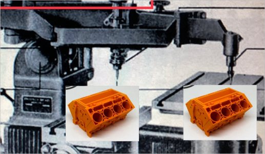
I am missing the factory “overarm” which converts the machine from a pantograph to a “straight” milling machine (part in red box). This overarm can also be used to attach patterns to follow when milling. No pattern => rigid spindle.
I get around the lack of the overarm by clamping the “pattern side follower” into a vise. Since the relative moment arms are huge, the spindle is held very rigidly for operations like the one I used it for on this project. I would not use anything bigger than a 1/4 cutter for any milling operation as the spindle, and pantograph mechanism for that matter, are delicate and could be damaged by large side loads.

Besides a little bit of manual engraving, this is the sort of stuff I have used the GK12 mostly. I only have the one 1/4” collet for it but I have made reducing sleeves for both 1/8” and 1/16” shank tooling. Comes in handy when you need to drill out a busted off HSS tap in a hole. The little carbide drills at high speed (and air cooling from the blowgun) make relatively short work of the tap. Saved my bacon a bunch of times…
I am missing the factory “overarm” which converts the machine from a pantograph to a “straight” milling machine (part in red box). This overarm can also be used to attach patterns to follow when milling. No pattern => rigid spindle.
I get around the lack of the overarm by clamping the “pattern side follower” into a vise. Since the relative moment arms are huge, the spindle is held very rigidly for operations like the one I used it for on this project. I would not use anything bigger than a 1/4 cutter for any milling operation as the spindle, and pantograph mechanism for that matter, are delicate and could be damaged by large side loads.
I am missing the factory “overarm” which converts the machine from a pantograph to a “straight” milling machine (part in red box). This overarm can also be used to attach patterns to follow when milling. No pattern => rigid spindle. I get around the lack of the overarm by clamping the “pattern side follower” into a vise. Since the relative moment arms are huge, the spindle is held very rigidly for operations like the one I used it for on this project. I would not use anything bigger than a 1/4 cutter for any milling operation as the spindle, and pantograph mechanism for that matter, are delicate and could be damaged by large side loads.
The mind reels at the possibilities! LOL
Attachments
RobinHood
Ultra Member
I know! And this is “only” a 2D pantograph. The bigger brother, the KF2, is the 3D one... (I am missing an attachment for it though…)The mind reels at the possibilities! LOL