lucsimoneau
Well-Known Member
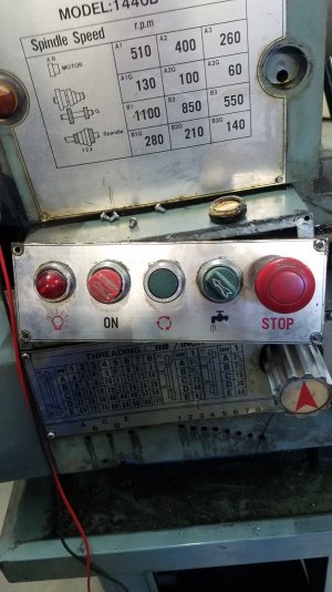
If you need more pictures let me know, here's what I've got


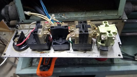
wow....thanksHave the exact same Lathe and here's how mine is wired ...
V --> Black
M6 --> White
U --> Red
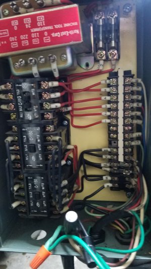
View attachment 41193
On dual voltage machines, this is customary. The mains cable can then be just 220 or 110V and the transformer makes the control voltages. it doe not produce enough VAs to power anything beyone the relays. I wired mine in the circuit, even though I had 110V available in the cable. Then I only moven one wire in teh control circuit, and rewired the motor for 220V, and that was it. 10 minutes. To bypass the transformer I'd have to remove both leads, add add teh 110V leg. prolly 10 minutes, but then I wouldn't conform to the 220V scematic, and that would offedn my undiagnosed OCD.The transformer is still a mystery - why have one if the output voltage is directly available?
")
You missed Great Britian and New Zealand, where *only* 240V is available.It is almost impossible to have 208 / 220 /240 without 120 like voltage available. All the NEMA and IEC and IEAD standards work that way. All the public electric grids in North America, Europe, Japan, 'colonial' south east Asia and Pacific islands and Australia work this way. Aviation and marine systems have different standards and there are lots of custom industrial ones too. And who knows what they do in Africa or any of the old Soviet places
Thanks LucGive me some feedback to see if this worked out for you.
Except that if you use that path won't your circuit breakers trip? Any GFCI would, at least.In both those countries, hot to ground is 120V
On dual voltage machines, this is customary. The mains cable can then be just 220 or 110V and the transformer makes the control voltages. it doe not produce enough VAs to power anything beyone the relays. I wired mine in the circuit, even though I had 110V available in the cable. Then I only moven one wire in teh control circuit, and rewired the motor for 220V, and that was it. 10 minutes. To bypass the transformer I'd have to remove both leads, add add teh 110V leg. prolly 10 minutes, but then I wouldn't conform to the 220V scematic, and that would offedn my undiagnosed OCD.