My apologies to the OP.
@Mcgyver has more guts than I do. I was (and, still am) very reluctant to comment on this thread. Too many things don't make sense, and I am always reluctant to give electrical advice to someone who is not electrically inclined.
BUT, I note that Mcgyver didn't provide specific wiring advice but did try to help anyway. He is a smart cookie and I agree with his comments 100%. That's been my
My apologies to the OP.
@Mcgyver has more guts than I do. I was (and, still am) very reluctant to comment on this thread. Too many things don't make sense, and I am always reluctant to give electrical advice to someone who is not electrically inclined.
BUT, I note that Mcgyver didn't provide specific wiring advice but did try to help anyway. He is a smart cookie and I agree with his comments 100%. That's been my guess from the first post.
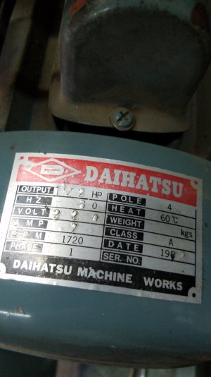
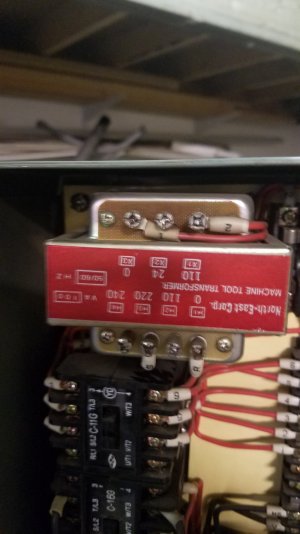
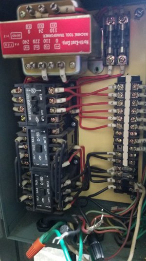
Just as an aside, in all my life I have never seen a machine that has a high hp motor wired for 220 with 110 in to the unit and a transformer in between.
I have seen lots of dual voltage motors that can be wired for 220 or 110.
I have also seen 220 in with a neutral and split output to a motor wired for 110.
I have seen lots and lots of 110 in with a 110 motor and lots and lots of 220 in with a 220 motor.
But NEVER 110 in with a motor wired for 220. NEVER.
A few guesses:
A Hill Billy might have used 110 Wire connected to 220 at both ends with no neutral. Wire is wire. If you ignore conventions and codes, it will work just fine.
Another guess is that you bought the lathe from a guy who wired it wrong, it never did work, and that's why he sold it.
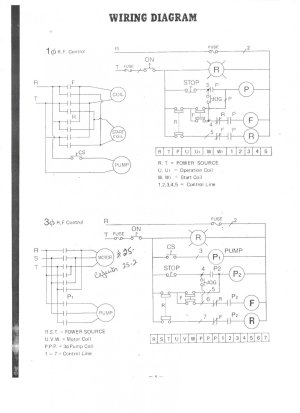
IMHO, you either have to find the wiring diagram for it or make your own. Other faster easier approaches might have a lot of appeal, but I don't think shortcuts are a good idea. The odds of magic smoke appearing in the works are simply too high.
Thanks....the more I think of what you said the more it makes sense. I will continue to my search.
guess from the first post.
Just as an aside, in all my life I have never seen a machine that has a high hp motor wired for 220 with 110 in to the unit and a transformer in between.
I have seen lots of dual voltage motors that can be wired for 220 or 110.
I have also seen 220 in with a neutral and split output to a motor wired for 110.
I have seen lots and lots of 110 in with a 110 motor and lots and lots of 220 in with a 220 motor.
But NEVER 110 in with a motor wired for 220. NEVER.
A few guesses:
A Hill Billy might have used 110 Wire connected to 220 at both ends with no neutral. Wire is wire. If you ignore conventions and codes, it will work just fine.
Another guess is that you bought the lathe from a guy who wired it wrong, it never did work, and that's why he sold it.
IMHO, you either have to find the wiring diagram for it or make your own. Other faster easier approaches might have a lot of appeal, but I don't think shortcuts are a good idea. The odds of magic smoke appearing in the works are simply too high.

")