• Scam Alert. Members are reminded to NOT send money to buy anything. Don't buy things remote and have it shipped - go get it yourself, pay in person, and take your equipment with you. Scammers have burned people on this forum. Urgency, secrecy, excuses, selling for friend, newish members, FUD, are RED FLAGS. A video conference call is not adequate assurance. Face to face interactions are required. Please report suspicions to the forum admins. Stay Safe - anyone can get scammed.

Tool Lathe Stops

Tool
These two links are in the Library plans threads.


I've updated the info on the Atlas Micrometer stop as "tomstechniques" website seems to be gone.
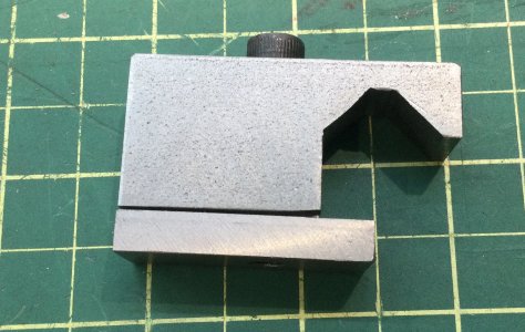
I combined the two stops and made mine for V ways and has the threaded spindle stop.
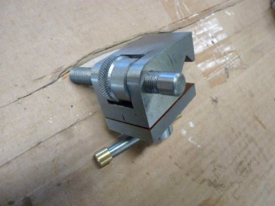
1731453658760.jpeg
 
Also few lathes have automatic OFF to their power feed when they hit a stop.
I've been mucking about adding this as a feature on my Clough-derived ELS. Put a micro switch in the stop wired to the ELS control. Could stop there and still maintain spindle-to-leadscrew synchronization. Even better if I gave it a wee shock absorber to mount it on to absorb the movement during the wind down without moving the stop.
 
@slow-poke Can I get a drawing for this? On my Craftex CX-706, the inverted V-ways are not 90 degrees. I think they are 93 degrees but may not be a whole number. On Blondihacks, Quinn mentioned her PrecisionMatthews has the same "feature". Yours?

Craig
Craig,

I actually made this for a CX-706.

I don't have a drawing but I can tell you the dimensions from my memory and scribble notes. Segment A and C are 10mm and segment B is 4.5mm.

Trying to measure that inverted V is tricky. The unknowns are:
1) Does the PM machine use the same ways, my hunch is yes because my buddy had the PM version and after comparing the two machines are conclusion was that other than paint color and accessories they are one and the same.
2) Is Quinn correct about the 93 degrees?

The 3D model is 90 degrees and actually fits quite well, from the video my 3D printed one seemed to fit better than her 93 degree aluminum version, so if the ways are not 90, they are very close, best measurement I could estimate was 90+/-1.

So I decided to make it 90 degrees and see what happens, I could possibly tweak an extra degree if it fit poorly. Turns out it fits quite well and clamps rock solid.

Lets call the slope next to the open end slope A and the inner slope, slope C, and the segment in between segment B
If you place your block at a 45 degree angle in your vise with C facing straight up you can use the end of a 10mm end mill to make that pass.

If you now don't move the part but simply lift that end mill to clear segment B you can use the side of the same end mill , to mill angle A at a perfect 90 degrees WRT angle C.

At this point there is a little triangle pointing up from segment B.
So now reposition the block with the long end straight down, and use the end of a 4.5mm end mill to flatten the triangle. I only had a 4mm so I used that and shifted it over 0.5mm to accomplish the required 4.5mm wide segment B.

Oh and then cleanup the little outside segment that is parallel to B

Hopefully my description is adequate?

Basically 4 passes in total, two with the 10mm and two with the 4.5mm, one position change in the vise.

5D416B22-AA65-42DE-AA29-1AF36C6EF239.jpeg
 
2) Is Quinn correct about the 93 degrees?

@trlvn - Easy to use a small V-Block and a flashlight on the backside to find out. I'd try it at the tailstock end so I could get my fat head down low enough to see any gaps. Mine is 90 for sure. 3 degrees is very visible. That's what the taper is on a grinding wheel arbour.
 
I *know* the angle is not 90. I have a small adjustable square (the length of the arm adjusts; not the angle) and it clearly shows daylight. I don't know with certainty what the angle really is. The surfaces are quite short and I don't have anything that will give me an accurate measurement.

I actually started a lathe stop project and, using angle blocks, cut out a 94 degree opening. I channeled my inner Joe Pie for the setups. I drilled and reamed a hole at what would be the apex of the inverted V. I set up the part at a 47 degree angle with angle blocks. Then used a gauge pin to let me find the top and sides of the hole. Alas, on the final cut, I forgot to allow for the radius of the gauge pin (I think) and cut the opening too large. Worse, when I was testing the fit on the lathe, it still had some slop. I've been meaning to have another go at it but...it has been over a year.

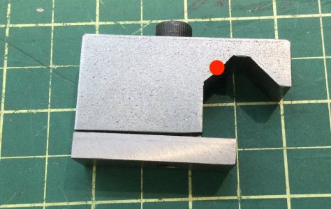
More recently, it occurred to me that perhaps I could use a round surface on one side for a single point of contact:

slow-poke-design-mod.jpg


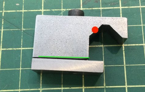
With a single point of contact, the exact angle doesn't matter. Using slow-poke's picture, I might make one with, say, a brass insert where the red dot is shown. Incidentally, I think a little relief cut (green line) would allow the clamp to work more positively.

One of these days...

Craig
 

Attachments

  • slow-poke-design-mod.jpg
    slow-poke-design-mod.jpg
    139.2 KB · Views: 1
I think a little relief cut (green line) would allow the clamp to work more positively.

The pin is a good idea. Can it be glued into a groove so a steel pin could be retained but still sit proud?

The green relief idea is also a good idea, but I'd leave a ridge furthest from the clamp area so the clamp has more leverage and doesn't sit on an angle.
 
Yes, the contact could benefit by a rounded section. OTOH for best clamp up there really should not be much if any angled contact, My screw turns maybe 1/4 turn from sliding loose to fully clamped.
You could drill a hole for a dowel pin beforehand, mill the top 1/3 away & insert the pin leaving that portion of the pin exposed (diameter = light press fit or Loctite retainer)
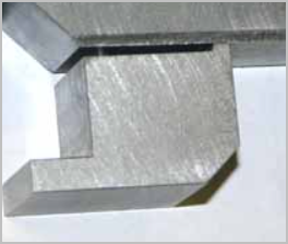
I just milled a relief leaving a small step & chamfered a bit with a file.

1731556088256.png
1731556444968.png
 
Back
Top