-
Scam Alert. Members are reminded to NOT send money to buy anything. Don't buy things remote and have it shipped - go get it yourself, pay in person, and take your equipment with you. Scammers have burned people on this forum. Urgency, secrecy, excuses, selling for friend, newish members, FUD, are RED FLAGS. A video conference call is not adequate assurance. Face to face interactions are required. Please report suspicions to the forum admins. Stay Safe - anyone can get scammed.
-
Several Regions have held meetups already, but others are being planned or are evaluating the interest. The Calgary Area Meetup is set for Saturday July 12th at 10am. The signup thread is here! Arbutus has also explored interest in a Fraser Valley meetup but it seems members either missed his thread or had other plans. Let him know if you are interested in a meetup later in the year by posting here! Slowpoke is trying to pull together an Ottawa area meetup later this summer. No date has been selected yet, so let him know if you are interested here! We are not aware of any other meetups being planned this year. If you are interested in doing something in your area, let everyone know and make it happen! Meetups are a great way to make new machining friends and get hands on help in your area. Don’t be shy, sign up and come, or plan your own meetup!
You are using an out of date browser. It may not display this or other websites correctly.
You should upgrade or use an alternative browser.
You should upgrade or use an alternative browser.
Lathe sine bar
- Thread starter Aliva
- Start date
Cool looking and prolly pretty easy to use. I just use a small square for 90s 45s and 30s. Yours would stay with your lathe and never get lost using it for something else. I like the magnets to hold it in place too.
Normally when I think of a sine bar, I think of something that uses stacking gauge blocks (or even just one) to set an angle based on its sine and the distance. So I'm curious about why you call that a sine bar?
Normally when I think of a sine bar, I think of something that uses stacking gauge blocks (or even just one) to set an angle based on its sine and the distance. So I'm curious about why you call that a sine bar?
With this I can create any angle on the compound by using gauges blocks under the pin closest to the tool holder.
Ah, I see! I didn't consider that those pins were a calibrated distance apart or that it was the long edge that you were using. So ya, now I see that it really is a sine bar and you are using it to set the compound angle not the tool holder. I had assumed you were using it to square up the tool holder. Silly me!
I didn't watch the videos. I hate YouTube. By all rights, you can tell me to pound salt right about now and I'll totally understand. But if you are more inclined to have some compassion.....
To set the compound, you still need a reference. Since I don't see one, I'm gunna assume you need to use an indicator. Your sine plate has the distance built in with the pin spacing so you have to use gauge blocks to set an angle and then use an indicator to make the back of the sine plate square to the cross-slide.
Unless, I'm mistaken (highly likely), you could take that to the next level by making something to square the sine plate to. Ie place the gauge blocks, loosen the compound, bring the plate up to a square of some kind and swivel it till it is a good fit to the square, tighten up the compound, and make chips! No indicator needed!
TorontoBuilder
Sapientia et Doctrina Stabilitas
Enots engineering has a build video for those wanting a lathe sine bar. It's high on my project list
@Aliva @TorontoBuilder
This lathe Sine Bar is a really cool idea. But it needs the improvement I mentioned earlier. I watched enough of the videos to confirm my suspicions - an indicator is needed.
We need to figure out how to do angle setups without an indicator. That is after all the primary benefit of a sine plate! The gauge blocks are supposed to be the measurement!
I spent some time yesterday looking at my cross-slide and compound with this goal in mind. I'll admit, my mind was a blank. Hence the confession here. It's a clear need waiting for a brain fart.
TorontoBuilder
Sapientia et Doctrina Stabilitas
I'm up for building one, since I'm going to do a ton of tapers.@Aliva @TorontoBuilder
This lathe Sine Bar is a really cool idea. But it needs the improvement I mentioned earlier. I watched enough of the videos to confirm my suspicions - an indicator is needed.
We need to figure out how to do angle setups without an indicator. That is after all the primary benefit of a sine plate! The gauge blocks are supposed to be the measurement!
I spent some time yesterday looking at my cross-slide and compound with this goal in mind. I'll admit, my mind was a blank. Hence the confession here. It's a clear need waiting for a brain fart.
I would like to compare it to the DRO function to see what is better
Xyphota
Ultra Member
Maybe one of the following?We need to figure out how to do angle setups without an indicator. That is after all the primary benefit of a sine plate! The gauge blocks are supposed to be the measurement!
1. If you trust your tailstock, you could use the extended barrel of the tail stock and butt up against that
2.Turn a bar between centers and butt up against that?
Last edited:
Maybe one of the following?
1. If you trust your tailstock, you could use the extended barrel of the tail stock and butt up against that
2.Turn a bar between centers and butt up against that?
Turning a bar is more complex than using an indicator.
I like the tailstock barrel idea. But the tailstock is high vs the compound surface. So it needs some more thinking.
Edit - while I'm adding thoughts, the standard sine spacing is 5". So that's what the standard gauge blocks are sized for. It would be good to figure out how to take advantage of that too. My compound is 7" long but the there is only 4" of free surface behind my tool holder. I suppose one could use 2.5" and standard blocks and double the marked angles. But again, some innovation is called for.
@TorontoBuilder - thanks for the reminder. I'm prolly gunna lose interest in the idea once I get a compound DRO working..... As I understand it, it will calculate and display the angle for you. But I don't know how that works.
Last edited:
If you trust your tailstock, you could use the extended barrel of the tail stock and butt up against that.
OK, I was wrong. The center of my tailstock is only 1.25 inches high from the top of my compound. Totally within range of dowel pins or a taller plate.
I didn't measure its squareness yet, but I'd fully expect it to be darn near perfect. I'll measure it shortly and find out.
Mine is 8 microns across 2.5" or 3 tenths of a thou. It's also solid as a rock.

So that will be plenty good enough for this type of usage.
Developing the idea a bit, the gauge pins on the sine bar just need to be proud on both sides. One side registers against the compound, and the other side against the barrel of the tailstock quill. Now we have an indicator free sine plate!
Who is gunna be the first to make the prototype? Won't likely be me. Planting time is here (waiting for my fertilizer blend right now), we are in the middle of moving my mom to long term care this week, and my bride is still being a stress nazi.
@Aliva - any chance those pins of yours will push through enough on your existing sine bar to maintain register on your compound AND contact the center of your quill?
I know, at some point, both the quill and the compound will need to be qualified.......
Which of course raises the question for me - is 8 microns over 2.5" a concern regardless of its applicability to a sine bar?
The pins on my bar are 50mm in length. Too short to reach the tail stock. But The pins could be replaced with longer ones I would think. I do like the concept of using the tail stock instead of the indicator.
Let us know how it goes! Now that I understand the concept, I'm anxious to see how well the tailstock quill reference works. I tried to fabricobble something quick but failed miserably. Nice thing about using 2.5 inch spacing is that it will likely fit the quill (it fits mine) and you can use standard blocks by simply multiplying the marked gauge block angles by two. I like that can set complimentary angles too just be choosing the appropriate pin to put gauge blocks under.
A question for you. How hard was it to establish an adequate/accurate location for the pins. I know that doesn't really matter once you introduce the tailstock quill concept, but there are always gunna be times when you need to use a different datum. So I'd still want to precisely locate the pins relative to the back surface.
@Susquatch tangent question - why do you have what looks like a feeler gauge shim under your tool post?

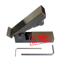
I thought I had some setup pictures in my album but I guess not. Anyways I bought one of these mini offshore magnetic sine bars. The general idea was to set the angle using standard gage blocks, lock it into position (it has a hex key lock). Apply that to a datum surface on the lathe & indicate off that by swiveling the compound so DTI reads zero traversing the block. In theory it should be quite quick & accurate especially for oddball angles requiring a bit higher precision. But the lathe datum surface is the trickier bit. Something like a faceplate is relatively straightforward, Its usually faced true or should be. Sufficiently magnetic, but you are kind of limited to smallish included angles relative to the plate. Large angles don't work well.
If you wanted to do a shallow angle relative to bed axis like MT taper, then the mini sine plate would ideally be position on something like a test bar or coupon extending from the HS. But a round bar does not play nice with a flat bottom sine bar & its probably same work to just do it directly with DRO & cross feed delta displacement. I have some ideas about making a 'chuck-able' sine bar that pivots & locks in either axis, but the need for odd + precise angles just doesn't seem to come up often for me. The best way IMO to make to taper shank arbors & such is with a taper attachment, which I don't have :/
I think the tailstock method its favored & taught because its always there & you don't have to disturb any work being held. Reasonably accurate, but its indirect. Hopefully is coincident to spindle axis, but if is not, you are just transferring any discrepancy. The DTI will display shallow angles relative to bed axis within limits of indicator & short barrel length, but its not conducive to small angles more relative to cross bed. So ind of depends what angles we are talking about.
Maybe one of you smart electronics guys can come up with a DRO protractor!
@Susquatch tangent question - why do you have what looks like a feeler gauge shim under your tool post?
Damn. Caught with my hand in the cookie jar! I considered removing it for the photo but figured nobody would notice it....... Ya, leave it you to let no little detail get by!
I was doing some experimenting and needed a perfectly level tool. It was easier to shim the tool holder than shim the tool. It doesn't live there.
Maybe one of you smart electronics guys can come up with a DRO protractor!
That feature is already built into my Ditron. To use it, I would have to install a scale on my compound. I'm not there yet......
Beautiful little sine bar! Of course, with no scale - it could be huge! I know you called it small, but how big is it? I don't suppose it's 2.5"???
I don't have a taper attachment either. I've always used a plunger indicator on the side of my compound and math. Perhaps that's why I love this gizmo that @Aliva has made (after I realized what it is! LMAO!) I have a nice set of angle gauge blocks that could easily be used to get any angle without math or indicators with a modified version of his gizmo. My blocks are marked with the dimension and the angle. Hence all this discussion about modifying Aliva's gizmo.
Its metric, 50mm centers
 www.ctctools.biz
MINI MAGNETIC SINE BAR #L36
TOOLMAKERS ANGLE COMPOUND SETTING MINI MAGNETIC SINE BAR
I further investigated using the tail stock barrel as a reference instead of an indicator. I can be done but,
the sine plate will need some modifications. The pin length has to be increased to 2 1/2" on order to contact the compound side face and the tailstock barrel. The pins will have to protrude approximately 1 1/2" beyond the top and 1" on th bottom of the sine plate. The distance that the pins are located from the edge of the sine plate has to be increase by about 1" otherwise the compound handle hits the tailstock body.
I measured the parallelism of my tailstock barrel and there is a.002 difference along the length. After using a sine bar calculator this introduces an error 2 minutes 17 seconds to the results. Mind you this is a very small amount so I guess I could live with it depending on how accurate I need the taper. If doing pipe threads this could result in a pass or fail, but I don't know.
On a Morse taper #3 using a 3" sine plate this error would increase the gauge block effective size by .023. A Morse taper #3 calls for a gauge block of .0753 with tailstock error this actually equates to .0773 gauge block even though I'm using a .0753 block.
The standard Morse #3 taper is 1*26'16". With tailstock error a 1*28'35" taper will result. How well would this taper fit? Don't know. Maybe someone could offer and opinion on this. FYI I used the sine bar calculator on the Little Machine shop web site
Below is a sketch of the sine plate mods.
Its metric, 50mm centers
Nice. I suppose I could grind my own gauge blocks for such a bar.
The distance that the pins are located from the edge of the sine plate has to be increase by about 1" otherwise the compound handle hits the tailstock body.
I don't understand this one Aliva. I was suggesting that the pins contact the tailstock, not the plate, nor 4 pins.
If the compound is too close, I suppose one could use a standard parralel bar to do the same thing.
Sometimes I am my own worst enemy. The goal is to make your simple plate even easier to use by eliminating the need to use an indicator. If we make it too complicated, we have defeated that objective.
But still, it's a worthy goal. Great ideas often build on other good ideas.
I measured the parallelism of my tailstock barrel and there is a.002 difference along the length.
And here I was wondering if mine was a problem! So you have answered the question. 2 thou is 2.5 minutes. Big deal.
Mine is 3 tenths over 2.5 inches or 0.4 minutes. I can't imagine that being much of an issue for most tapers. I think it is important to remember that there are lots of sources of error in such systems. It's prolly not wise to be too anal about it.