• Scam Alert. Members are reminded to NOT send money to buy anything. Don't buy things remote and have it shipped - go get it yourself, pay in person, and take your equipment with you. Scammers have burned people on this forum. Urgency, secrecy, excuses, selling for friend, newish members, FUD, are RED FLAGS. A video conference call is not adequate assurance. Face to face interactions are required. Please report suspicions to the forum admins. Stay Safe - anyone can get scammed.

Lathe Cross-Slide Lock

But I was more apprehensive of buggering of the gib.
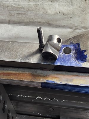
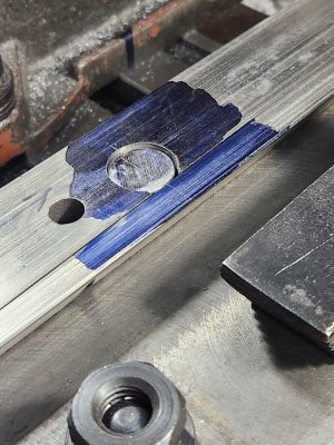
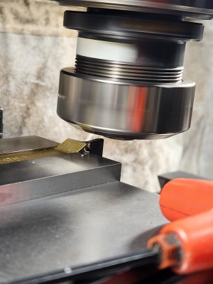
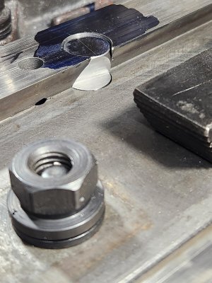
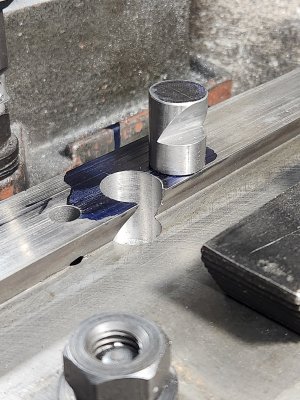
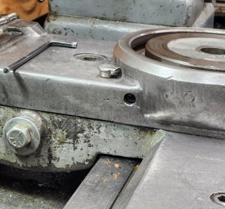
So I tried this first & it worked. To recap = the brass angle mates the gib angle & presses laterally. Yes its bending the gib, but I would guess very little just based on the existing sliding fit.

Other than marring of the surface with a turning screw end, I wouldn't worry about damaging the gib. As you say, it's already a close fit and can't really bend much at all. The main locking force isn't the wedge or the screw anyway. It's the fact that the dovetail on the opposite side locks across its whole length that locks everything up solid.

When I install my DRO (hopefully this summer) I'll take a really close look at making a wedge arrangement for mine if only to reduce the marring that will inevitably take place with a lock screw that is turning against the gib.
 
That's true, bite marks are unsightly but mostly harmless because they are on opposite side of critical sliding surface. But an undesirable secondary issue is when you torque a plain screw edge against the gib strip, it can have enough torque to displace the slide itself. I've proven this to myself many times on both lathe & mill with same mickey mouse system. But its really evident when you install DRO which records the event. Set DRO to 0.0000", lock table, DRO now says 0.0025". That's a bad thing. Locking is not just about securing the slide, its about freezing a particular position during a machining operation.
 
I've proven this to myself many times on both lathe & mill with same mickey mouse system.

Yup. Absolutely true. I've seen it many times too. So ya, that's gotta get fixed!

Remember our discussion about gibs rotating upward because of the adjustment screw? I think we wore out everyone else's patience on that one, but it was an absolutely great discussion.

I'll never be able to look at a gib again without remembering all that mental geometric acrobatics! Might even be why I had a stroke shortly afterward! LOL!
 
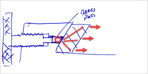
I also would not worry about damaging the gib. I've seen the arrangement that Robbin showed, and also set ups like the sketch below with a brass pad. Below imo would be the easiest to implement. On straight gibs, instead of tapered, you can just make a flat counterbore into the gib with a flat bottom drill as the gib doesn't move relative to the lock

1707590976929.webp
 
That's essentially what my brass shoe does. Actually because (at least on mine) the threaded hole is same diameter right through, maybe a ball end might serve the same purpose since its just translating the force to the broader gib strip area anyways. I just like the idea of matching angle & wanted to work with existing M6? hole if possible. My RF-45 mill had 2 lock screws spaced apart. Probably a few ways to skin the cat.
 

Attachments

  • EDT-10-02-2024 11.59.40 AM.jpg
    EDT-10-02-2024 11.59.40 AM.jpg
    35.4 KB · Views: 1
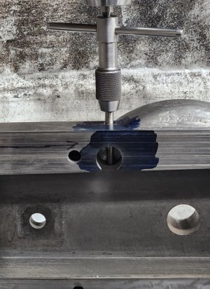
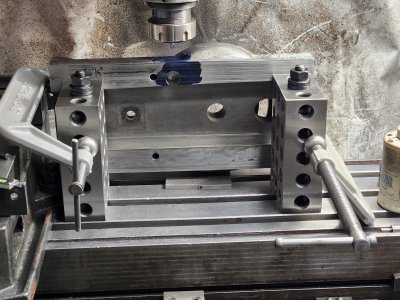
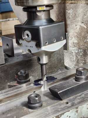
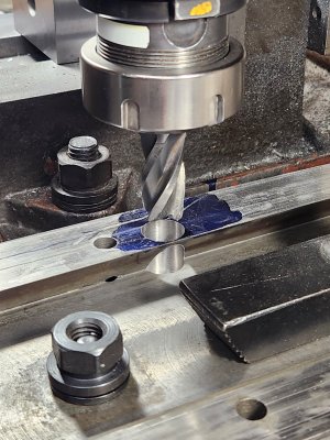
Ok ladies and gentlemen (do we have any women in this group?). It works!! Doesn't need much tension and locks up solid. I couldn't budge the cross-slide with all my weight.
 

Attachments

  • 20240210_175846.jpg
    20240210_175846.jpg
    297.8 KB · Views: 14
  • 20240210_165513.jpg
    20240210_165513.jpg
    502.2 KB · Views: 12
  • 20240210_162637.jpg
    20240210_162637.jpg
    673.7 KB · Views: 11
  • 20240210_150031.jpg
    20240210_150031.jpg
    497 KB · Views: 12
  • 20240210_145431.jpg
    20240210_145431.jpg
    275.2 KB · Views: 13
  • 20240210_143808.jpg
    20240210_143808.jpg
    407.5 KB · Views: 12
  • 20240210_143758.jpg
    20240210_143758.jpg
    502.2 KB · Views: 11
  • 20240210_143651.jpg
    20240210_143651.jpg
    643.5 KB · Views: 10
  • 20240210_132356.jpg
    20240210_132356.jpg
    459.3 KB · Views: 12
  • 20240210_131616.jpg
    20240210_131616.jpg
    488.1 KB · Views: 15
  • 20240210_130700.jpg
    20240210_130700.jpg
    624.4 KB · Views: 15
  • 20240210_181825.jpg
    20240210_181825.jpg
    698 KB · Views: 15
Back
Top