• Scam Alert. Members are reminded to NOT send money to buy anything. Don't buy things remote and have it shipped - go get it yourself, pay in person, and take your equipment with you. Scammers have burned people on this forum. Urgency, secrecy, excuses, selling for friend, newish members, FUD, are RED FLAGS. A video conference call is not adequate assurance. Face to face interactions are required. Please report suspicions to the forum admins. Stay Safe - anyone can get scammed.

Lathe Cross-Slide Lock

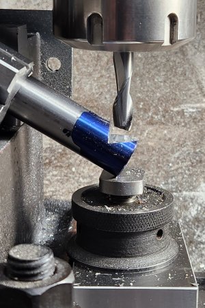
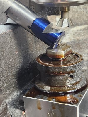
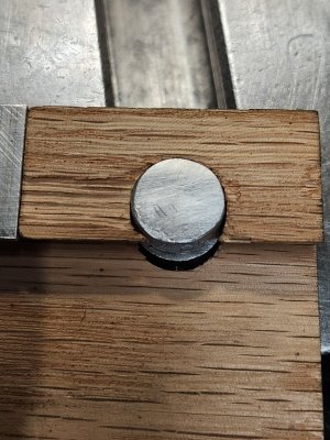
Yes, it's upside down.

The tighening bolt is on the side. There was no room for me to mount it up top except near the ends of the gib, and that probably wouldn't give a lot of force. So on the side, I can put the lock at the middle of the gib.

Handle, maybe. We'll see.
 

Attachments

  • 20240210_085058.jpg
    20240210_085058.jpg
    414.3 KB · Views: 7
  • 20240210_090611.jpg
    20240210_090611.jpg
    486.8 KB · Views: 7
  • 20240210_091846.jpg
    20240210_091846.jpg
    427.9 KB · Views: 7
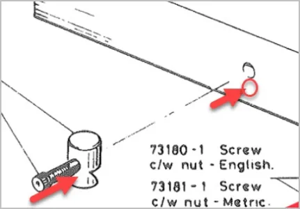
Have a look at the lock circled in red.

Now I'm even more confused.

So that wedge doesn't slide on the gib bar and cam to make it tight? It just presses on the gib? And I assume the screw hole is threaded to facilitate that?

Wouldn't it be better if the screw pulled the wedge up so it tightened against the gib as it slid up more gradually?
You'll have to go read post #9-#14 of this thread. I was confused when @RobinHood described it.
 
I thought I understood the lock principle but maybe not really after all. I wonder if the cylindrical profile is more to give the cross screw a higher elevation to impart force, otherwise it would be quite low in the casting if it was acting more obliquely to the dovetail? For some reason I thought the cylinder pulled up but I don't think so? Its a glorified shoe?
 

Attachments

  • EDT-10-02-2024 9.36.37 AM.webp
    EDT-10-02-2024 9.36.37 AM.webp
    12.3 KB · Views: 3
What I forgot to say - if the cylinder acts as a shoe, I don't understand how it displaces laterally inward, its constrained by the hole in the casting. Obviously I am missing something fundamental
 
What I forgot to say - if the cylinder acts as a shoe, I don't understand how it displaces laterally inward, its constrained by the hole in the casting. Obviously I am missing something fundamental

I missed that. You are right though.

I'm still reading "slowly"......

I happen to be in my shop right now, so I looked at mine more closely. It is a very simple grub screw pressing against the gib. Nothing more. No shoe to spread the load. That should be fixed. Well worth the time spent trying to see what @RobinHood & @thestelster are on about.
 
What I forgot to say - if the cylinder acts as a shoe, I don't understand how it displaces laterally inward, its constrained by the hole in the casting. Obviously I am missing something fundamental
The hole that the cylinder goes into is slightly oblong so it will move inwards. When I did the mock up in wood, I made the hole oblong by 0.040". And it locked everything very solidly. (Of course that was just with oak).
 
A steel shoe on (cast iron?) gib may not be bad over this large area birds beak profile, but brass or something sacrificial might be safer. My mickey mouse set screw lock acted directly on the gib strib & it had a series of circular bite marks down it. Now that was a very small, localized area. That's what prompted me to replace the screw with a profiled brass shoe & bearing ball arrangement. But you might not have the same available room
 
Could you accommodate something like my post #5? Its just one lateral screw which you are drilling anyways. Really you could have 2 for twice the grip retention. I can tell you my single locks it quite well for most operations.
 
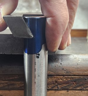
Slight gap allows the lock enough movement to squeeze the gib.
 

Attachments

  • 20240210_121052.jpg
    20240210_121052.jpg
    447.6 KB · Views: 1
Could you accommodate something like my post #5? Its just one lateral screw which you are drilling anyways. Really you could have 2 for twice the grip retention. I can tell you my single locks it quite well for most operations.
I was thinking of doing that, but I only have about 1" width of cast iron, so to accommodate the shoe and the ball bearing, I didn't think I would have enough room for the threaded section.
 
You'll have to go read post #9-#14 of this thread.

OK, I have read those posts slowly and very carefully.

Although your hand drawing seems to be missing the Gib, @RobinHood 's hand drawing shows it.

I "BELIEVE" I understand now.

I can't really criticize the shoe because my lathe doesn't even have that! Just a grub screw that presses against the gib. A shoe would be 10x better.

Since the gib and shoe or even just the screw don't change position unless the gib is adjusted, I don't think the overall repetition of using the same spot has a big impact on wear on the gib from the shoe or the screw - the screw being far worse.

In hind sight, perhaps a simple pressure shoe is better than a
cammed shoe - less wear.

My lathe has no shoe at all.

If I were to add one, I would add a pocket for an internal shoe and use a front threaded hole to allow the screw to tighten the shoe. Mostly because my existing screw is online with the gib, not above it.

I think a sliding shoe is overkill and not necessary.

If I do this, it will be while I install a DRO on the lathe.
 
Both the compound lock and the cross-slide lock use a wedge profile (brass) pushing on the gib strip. These profiles are shown in the red and green circled areas in post #9. They are shown outside of their actual location.

A) Compound

The locking bolt passes through the wedge in a clearance hole and threads into the CI body of the movable part of the compound. As @thestelster points out, the hole in which the wedge sits it slightly oversized. When the SHCS locking bolt is nipped up, it pushes the wedge onto the gib with in turn pushes hard against the stationary part of the compound, thus locking the compound solid.

B) Cross Slide

The locking bolt is threaded into the wedge. When the SHCS in the movable part of the cross slide is nipped up, the wedge is pulled up in its close fitting bore and the angled portion (shoe) pushes on the gib which is in turn forced hard against the stationary (saddle part) of the cross slide, thus locking it solid.

The wedges have a relatively large surface are an thus the locking force is spread out. Also, the dove tail geometry is not distorted as is the case with set screws pushing against the gib.
 
Yes I thought about milling a flat recess along the gib so the existing lock screw could engage onto material that would not affect the important slide surfaces. But I was more apprehensive of buggering of the gib.
So I tried this first & it worked. To recap = the brass angle mates the gib angle & presses laterally. Yes its bending the gib, but I would guess very little just based on the existing sliding fit. The bearing ball is attached to cross bolt end with Loctite & engages matching cup profile made with regular ball end mill. This single 'assembly' you could multiply with another further down the slide. I'd mock it up in wood while you're at it & see of you like it.

BTW this is going into the hole preceding the bolt, so you need some way to remove it. I didn't think about that until later. If the ball is steel it comes out with a magnet, but brass shoe & stainless ball.... not so much. Chewing gum?

1707586560809.png
 
Back
Top