• Scam Alert. Members are reminded to NOT send money to buy anything. Don't buy things remote and have it shipped - go get it yourself, pay in person, and take your equipment with you. Scammers have burned people on this forum. Urgency, secrecy, excuses, selling for friend, newish members, FUD, are RED FLAGS. A video conference call is not adequate assurance. Face to face interactions are required. Please report suspicions to the forum admins. Stay Safe - anyone can get scammed.

Lathe Alignment

YotaBota

Mike
Premium Member
I was doing the "what if" scenerio, there are four mounting bolts on the HS end so there could be the ability for a minor adjustment but I'm not to concerned. Even if there is a bit of an alignment issue, the machine is still way better than I am, LOL.
I never took the HS off when I was doing the cleaning but I would guess it's the same as Robinhoods.
And we get things to tenth over 2 feet not a thou :D
What do you mean "we"- you must have a mouse in your pocket. LOL
 

Mcgyver

Ultra Member
What do you mean "we"- you must have a mouse in your pocket. LOL

you too, if you tried scraping. Not suggesting you should (its a bit of rabbit hole sane people are best to avoid), however while the accuracy, despite being true, sounds like a big boast, its mostly just the natural outcome of the process (accuracy of the reference flat, resultant depth of the layer of blue, the DOC, etc)

EDIT, I'd add my thinking and remarks are for SM's which are inverted way lathes (or the ones I've seen are). As Robinhood points out others don't register on the V and are adjustable
 
Last edited:

PeterT

Ultra Member
Premium Member
Nope, am more or less STRICTLY talking about step 1. Step 2 is easy stuff. Any discussion about step 2 is only an effort to avoid duplication. Cutting is only required in Step 1, not 2.

Yes, I recognize that you are doing it without cutting, but I am not convinced (yet anyway) that this can be done. In my opinion, doing it without cutting would require that your MT5 (plus adapters) is ALWAYS concentric to the spindle but I doubt that it is. You will have to convince me of that or perhaps I will have to convince myself! LOL!

The purpose of my dumbbell (as you call it) is to keep the amount of cutting to a minimum and subsequent measurements to a closely constrained location. Nothing more or less.

To avoid confusion, let's stick to the step one piece of this until the horse is dead and further flogging is pointless.

I'll remember to come back to your thoughts on step 2 when that time comes.

So if we are back to Step-1 please explain how you are using the dumb bell profile test bar to verify the spindle is aligned to the ways.

[spindle picture reference] I mentioned that I have higher confidence that the spindle internal MT taper grind probably is as accurate as any other of the governing spindle surfaces because its logical (to me) they would preserve the same rotational grinding setup when ALL the governing surfaces are done - bearing OD's, journal surfaces, vertical end surface & internal socket. I don't know that for a fact but logically, why disturb the setup, remove the spindle to another setup & risk an inferior job grinding the MT5 surface? So sure, we could second guess or speculate the ground MT5 axis is not coincident with the main spindle axis, but I'll leave that to you somehow ascertain with measurements. We can just keep going down that speculation path & say the spindle axis is perfect but the nose taper & end surface is out, therefore every chuck which is mounted will always have misaligned axis. One of the purposes of MT taper is to directly plug in tooling which depends on coincident axis, so it's kind of an important surface. Could the MT3/MT5 socket adapter be out? Sure. I could have purchases an MT5 ended test bar if I were pickier. They are centerless ground so no end-centers drills are involved. Are they within a tenth as the cheesy documents state? I don't know, I don't have the equipment to test it. But I'm more confident of that end result of what I can cut in my lathe.

[headstock reference picture] This is my lathe. Other lathes are completely different, but a lot of the Asian bolt-on headstocks are generically similar. It has grub screws which bear against the HS casting lip & therefore dictate how the headstock sits in yaw axis relative to the ways. Breathing on the screws the wrong way can have dramatic influence on the HS alignment. This makes sense when you consider the short couple of the set screw distance on even a fine pitch thread. Some people have observed HS taper cutting problems post-move & as the story evolves oh, the HS was removed to get down the stairs. Or the sling was wrapped around HS & the machine did a few aerial piro's before moving from A to B. Or things shift over time.

So now if we are talking Lathe-X which does not have this adjustable HS feature, or a different feature, or HS is integrally uni-cast with bed prior to spindle bearing boring... then of course all aforementioned bets are off. So the very first thing that should be identified when this subject arises is: what kind of lathe are we talking about? My point is, some people chuck some stock, make a cut, observe different resultant diameters & go chasing down foot level adjustment (lathe bed twist) because someone told them that's how its done, & don't even realize these screws reside on their machine. Now you potentially have 2+ independant problems, not just one. If the machine does not have HS yaw adjustment, you are left with fewer remedial options as mentioned by others in the post.
 

Attachments

  • EDT-2022-02-13 1.42.50 PM.jpg
    EDT-2022-02-13 1.42.50 PM.jpg
    82.5 KB · Views: 6
  • SNAG-2022-02-13 1.49.48 PM.jpg
    SNAG-2022-02-13 1.49.48 PM.jpg
    31.7 KB · Views: 6
Last edited:

PeterT

Ultra Member
Premium Member
My lathe has 6 floor screws. They are used to exert pressure under the head to make minute alignment changes.
I would think some similar adjustment is possible on any lathe. Even one with just 4 feet.
When you say 'floor screws' do you mean the typical adjustable jacks (aka levelling pads) between the lathe base/stand & floor? Or some other kind of adjuster?
Unless you have something different which I'd be interested to see, I would phrase this as 'adjusting twist to the lathe bed' (not just under the head). The carriage rides along this new path & does what it does to the rotating part in cutting mode, but the HS is basically locked in a short, localized position on the bed.
 
Last edited:

Susquatch

Ultra Member
Administrator
Moderator
Premium Member
So if we are back to Step-1 please explain how you are using the dumb bell profile test bar to verify the spindle is aligned to the ways.

[spindle picture reference] I mentioned that I have higher confidence that the spindle internal MT taper grind probably is as accurate as any other of the governing spindle surfaces because its logical (to me) they would preserve the same rotational grinding setup when ALL the governing surfaces are done - bearing OD's, journal surfaces, vertical end surface & internal socket. I don't know that for a fact but logically, why disturb the setup, remove the spindle to another setup & risk an inferior job grinding the MT5 surface? So sure, we could second guess or speculate the ground MT5 axis is not coincident with the main spindle axis, but I'll leave that to you somehow ascertain with measurements. We can just keep going down that speculation path & say the spindle axis is perfect but the nose taper & end surface is out, therefore every chuck which is mounted will always have misaligned axis. One of the purposes of MT taper is to directly plug in tooling which depends on coincident axis, so it's kind of an important surface. Could the MT3/MT5 socket adapter be out? Sure. I could have purchases an MT5 ended test bar if I were pickier. They are centerless ground so no end-centers drills are involved. Are they within a tenth as the cheesy documents state? I don't know, I don't have the equipment to test it. But I'm more confident of that end result of what I can cut in my lathe.

[headstock reference picture] This is my lathe. Other lathes are completely different, but a lot of the Asian bolt-on headstocks are generically similar. It has grub screws which bear against the HS casting lip & therefore dictate how the headstock sits in yaw axis relative to the ways. Breathing on the screws the wrong way can have dramatic influence on the HS alignment. This makes sense when you consider the short couple of the set screw distance on even a fine pitch thread. Some people have observed HS taper cutting problems post-move & as the story evolves oh, the HS was removed to get down the stairs. Or the sling was wrapped around HS & the machine did a few aerial piro's before moving from A to B. Or things shift over time.

So now if we are talking Lathe-X which does not have this adjustable HS feature, or a different feature, or HS is integrally uni-cast with bed prior to spindle bearing boring... then of course all aforementioned bets are off. So the very first thing that should be identified when this subject arises is: what kind of lathe are we talking about? My point is, some people chuck some stock, make a cut, observe different resultant diameters & go chasing down foot level adjustment (lathe bed twist) because someone told them that's how its done, & don't even realize these screws reside on their machine. Now you potentially have 2+ independant problems, not just one. If the machine does not have HS yaw adjustment, you are left with fewer remedial options as mentioned by others in the post.

Let's try to keep in mind that I am scoping out an improved way to align the headstock here. I think we should avoid debating the merits of your preferred way to do it as that turns into a me VS you argument. Your method works for you and my old method (which wastes a lot of metal) works for me.

I'm looking to move my method forward another level. I'm not trying to tell you that your method sucks. Although I do confess I probably erred in judgement by saying that I didn't trust a MT to be sufficient without making a cut. I should have just let that be and accept that you like it. My apologies.

The method that I have used is the one outlined in numerous manuals. It first involves levelling the bed to remove twist. Secondly, it involves chucking a bar in the lathe and taking cuts end to end until the bar is clean. The next step is to take a very fine cut end to end to avoid loading the bar and influencing the results. A test dial indicator (0.0001) is used to evaluate the top runout of the bar at both ends. And a regular 0.0001 Micrometer is used to evaluate the change in diameter - if any. These two pairs of measurements tell the user how much the alignment is off. Corrections are made and another cut is made. It doesn't take very long to consume a whole bar this way.

Yes, my method involves using 4 of the floor mounts to level the bed, and the remaining two to adjust the head alignment. You are absolutely correct to be sceptical of this way of levelling the lathe. Nonetheless, it works. Try to think if it as an inherently fine adjustment as it takes a lot to move the alignment even just a tiny bit.

I would invite you to review the web for the methods that are used. You will find this to be the main one out there

Now comes my "improvement". I got to thinking that you don't really need to measure more than the ends of the bar, the bar is slowly consumed by the testing process, and the bar used is normally very short which makes a precision adjustment difficult.

So why not add "consumable collars" to the test bar and use them as cutting and measuring surfaces instead of the bar?

And why not use a longer pipe to gain resolution while simultaneously increasing stiffness (reduced bending with length).

It's just an idea Peter. An idea for an improvement that I would like to discuss with others here. Even if you think the idea is stupid, (which it might well be) your input in that respect is valuable and appreciated.

In the meantime, I ran across a video done by Joe Pie that demonstrates my current method.


PeterT

Ultra Member
Premium Member
@Susquatch I've tried to be as clear as I can. Its not personal at all. Its not my method or your method. Its just geometric outcome based on a particular sequence of steps. Please go back & read my post #23 again because I think you are missing some key points.

The method that I have used is the one outlined in numerous manuals. It first involves levelling the bed to remove twist. Secondly, it involves chucking a bar in the lathe and taking cuts end to end until the bar is clean.
What manuals? What lathe? It's critically important to define this from the outset. A lot of the older literature pertains to older lathes where the HS was essentially fixed to the bed. But you can't just jump to that conclusion & generalize. If the lathe in question is the kind whereby the HS can be adjusted/displaced in yaw independent of the bed (which many modern lathes are especially the hobby Asian variety), then this angular latitude can easily override any amount of lathe bed jacking you could reasonably impart. For example, assume 100% untwisted bed, its perfect. Viewing from top, if HS is yaw pointing to rear of lathe & you take a cut, the bar will be larger diameter on TS side for that reason alone. Conversely if the HS is pointed to front of lathe, the bar will be smaller diameter on TS side. Are we in agreement? So the observed diameter reduction has nothing to do with bed twist. This HS alignment to bed is what I called Step-1. Now if you choose to ignore Step-1 & proceed directly to Step-2 & start twisting the bed to compensate so the bar reads equal diameters, that's an option too. But IMO it's just wallpapering over the first unresolved problem, so now you have 2 competing issues instead of what could actually be zero issues if you identify geometry in a stepwise sequence.

Now If the lathe HS is essentially fixed to the bed, by integral casting, permanently keyed, whatever - there is no Step-1. All you have at your disposal is bed twist adjustment. Beyond that its a more involved re-build.

I've seen Joe's Apr-2019 video & others like them. His cardboard model & even his verbiage ~3:00+ is saying the exact same thing as my post #23 in different words. The headstock is presumed essentially fixed & the ways outboard of the HS are presumed variable. Tony's Oct-2016 video says much the same.


Susquatch

Ultra Member
Administrator
Moderator
Premium Member
Please go back & read my post #23 again because I think you are missing some key points.

OK, I've read ALL your posts several times again and tried my best to do two things.

1. Figure out what you are trying to tell me. In doing so, I have assumed that you do have a good point to make. You always do.

2. I have also tried to assume that where ever we fell off, that it is my fault that it happened.

After doing so, I conclude that you are trying desperately to explain something I already know. And at the same time, I am asking a question that you are not answering. Instead you are answering a question I did not intend to ask. Without any question, this is my fault for not being clear and for saying things that caused this derailing. At least that is my self analytical conclusion.

Please understand. While I am a newbie at using a full size knee mill, I am a very old hand at using a lathe.

Peter - I know how to align the head on my lathe to the bed. I am NOT asking how to do that.

I confess I was critical of your MT5 mounted bar method. And this criticism probably did leave you to believe I didn't know how to align my head. This was my fault. And again, I apologize.

Perhaps worse, I wasn't clear at all about what I WAS asking. Again, my apologies. I will ask again shortly below and I'll try to be as clear as I possibly can.

What manuals? What lathe? It's critically important to define this from the outset. A lot of the older literature pertains to older lathes where the HS was essentially fixed to the bed. But you can't just jump to that conclusion & generalize.

I agree on all counts. For those who don't know how their own lathe is aligned, this is critical knowledge. You certainly can't align a head if you don't know how to do that on your own lathe.

However, I do know how mine is aligned. And again, this is not my question.

This guy drives me batty but at ~11:00 another example of pivoting HS, Hermes lathe.

Frankly, he drives me batty too. That said, almost all youtube authors drive me batty. So I won't hold it against him or anyone else.

Nonetheless, it is a good video to that shows some of my issues and background.

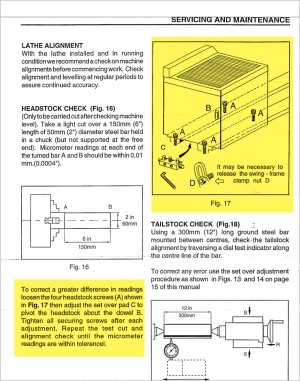
At 5:50 he explains how his lathe is aligned using the lathe cabinet feet. That is the same method as mine uses.

Also, at 12:42 he explains how he uses cuts on a bar to evaluate his alignment. This is also the method that I use.

But please note that there are a few problems with his method. Hopefully, I can address those as I ask my question again more clearly.

------------------------------------------

So what is the question that I am I asking? Before I actually ask, let me make a few statements.

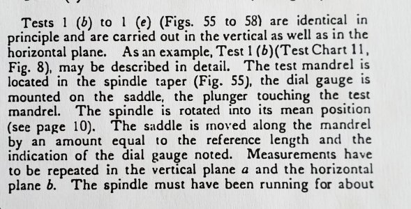
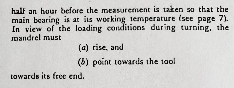
Many machinists take cuts on an unsupported test bar to test for the correct alignment of a lathe head to the lathe ways. That is the method used in the video you posted. This is also my method and I don't want to change it. However, I do want to improve it. In fact, I want to improve on this method in two ways.

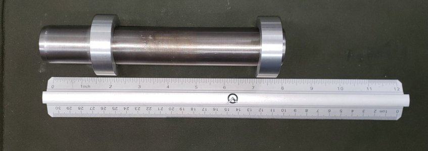
1. I want to use replaceable collars to avoid wasting a lot of material on my test bar.

2. I want to use a longer test bar to improve resolution.

These are two improvements that have some challenges buried in them. My questions address these challenges.

Question #1 - How do I attach replaceable aluminium collars to the test bar in a way that makes them: a) easy to change, b) does not introduce an interrupted cut for a fastener, c) does not weaken or reduce the rigidity of the test bar in any way, & d) minimizes any bias in the far end cut due to tool pressure during the cutting process.

Question #2 - What is the best way to compensate for the increased "droop" caused by the weight of a long test bar? I have assumed that a large diameter steel pipe had the highest resistance to bending under its own weight. I think this 2nd question is an ideal one for you @PeterT because you love to do drawings that analyse geometry. ;)

Further discussion:

Attaching a shouldered flange collar could be done with grub screws in the shoulder. But this makes the collars more difficult to make and requires more and bigger stock which is counterproductive to my goal of reducing the waste of good stock.

The collars could be glued on - but this would need to be removable glue to make them replaceable.

A double sided collet of some kind could be employed to grip the pipe and hold replaceable collets.

Permanent shoulders could be used and large aluminium washers (acting as replaceable collars) could be screwed to the permanent shoulders from the side.

The collars can be thin to reduce the machining required.

But my main focus at this point has been on the bar itself. I have found through experimental analysis that a 24" long 1-1/4 inch pipe bends about 1 thou under its own weight. I suppose that a 1-1/4" aluminium pipe might bend less due to a higher strength/weight ratio. But an aluminium pipe would also bend more than a steel one under tool pressure which might be worse.

Frankly, I'm not even convinced that longer is better anyway. I've never used a long one in the past and I've never seen anyone else using a longer one. So perhaps this is mostly a tail chasing game. Or are others just more scared of a long bar whipping around, or tool pressure deflection, or or or. To me, the question is simply not simple! If it were, I wouldn't be here asking about it!
 

Susquatch

Ultra Member
Administrator
Moderator
Premium Member
Another thought on cutting the collars would be to finish my new tool post grinder and use that to do the test cuts. I "believe" that might address the tool pressure deflection issue on a longer bar.
 

thestelster

Ultra Member
Premium Member
This is my test bar. It serves double duty. For tweaking alignment of head, by chucking the left side only, or tail stock alignment, put between centers. The bar is 8" long steel, 1.250" in diameter. The aluminium rings are 2" in diameter 5/8" wide. The rings ID were bored for a slip fit over the steel rod and are attached with green Loctite. If I ever need to replace them, a little heat and they'll come off. The head stock of my lathe sits on the bed. There is no provision for alignment. Hopefully the manufacturer ground and scraped the headstock for proper alignment. If that was perfect, and the spindle bore and bearings and shaft, etc, were perfect, and the bed ways and v's were perfect, and if we bolted the lathe to a solid concrete foundation, and leveled the ways perfectly. We just might get perfect cuts! Ha! Good luck with that!

I do not have an alignment mandrel which goes into the head stock. And the ones that I have seen on-line are solid units. In Dr. Schlesingers treatise, "Testing Machine Tools", he describes the construction of the test mandrels as being hollow, to reduce the influence of gravity. Therefore I can't readily measure if the headstock is out of alignment. But even if I did and determined it was way off, attempting to scrape that would kill me. So if I've leveled my lathe as perfect as I can get, and I'm turning a slight taper, my only fix is to jack up one of the corners at the tail stock end. Even lifting a corner 0.002" will make a difference on the cuts on my test bar. Does that mean my lathe is now perfectly aligned? Yes, but only at the section of the lathe, over the distance between the aluminium collars. So I can now turn a chucked bar for 5", and know that it will cut to a couple tenths or less....today. Next month might be a different story because everything shifts. Why did I only make my test bar 5"? Any more than that, and chatter happened. And besides, can you realistically turn something longer only chucked with no support.
 

Attachments

  • 20220215_103429.jpg
    20220215_103429.jpg
    180.9 KB · Views: 9
  • 20220215_104756.jpg
    20220215_104756.jpg
    368.6 KB · Views: 9

Susquatch

Ultra Member
Administrator
Moderator
Premium Member
This is GREAT STUFF @thestelster. And EXACTLY the stuff I am interested in. I especially like your collars. They are like what I had in mind. I like the green loctite too. Certainly a lot simpler than what I had in mind. I always did like KISS. To be fair, someone else suggested loctite too - just not green. Green should work. I will see.

Your reference to Schlesingers reference is also spot on. In reviewing that section of his work, I note that he didn't even try to "compensate" for the bending due to weight/gravity. I think this warrants some additional study. In my feeble mind, I think it ought to be possible to use a calibrated calculation (a more modern concept than used by Schlesinger) to determine the impact and include it in the adjustment. I'll have to see about that as time passes.

I am pretty sure I can go way beyond 5" without chatter. I've already been thinking about it though. A shear tool should reduce that problem and a grinding wheel should clobber it.

Can I realistically turn something longer with no support? Of this I am certain. Yes I can. I already cleaned up the far end of my 24" pipe that way using extremely fine cuts with an extremely sharp hss bit at 70rpm. My biggest worry would be the tool catching. But again, a shear tool or better yet a grinder should fix that.

The bigger question in my mind isn't really can I. The bigger question is why bother! I can see the point of 10 inches, but why 24? Because I can? Not a good reason. Because it's important? I don't think so. The vast majority of my work is all within 6 inches of my spindle. Anything beyond that almost always uses a center on the tailstock. Very few exceptions anyway and even those that do - do not require precision.

Most likely, this part of the question is just a curiosity exercise. But I like those because of what they teach me.
 

thestelster

Ultra Member
Premium Member
Your reference to Schlesingers reference is also spot on. In reviewing that section of his work, I note that he didn't even try to "compensate" for the bending due to weight/gravity.
Actually he does. See the attachment. He says there should be some inclination upwards and towards the operator, both at the head stock and the tail stock. But doesn't give an amount. Which would depend on the weight and length of the piece being turned and perhaps the cutting forces involved.
 

Attachments

  • 20220215_120442.jpg
    20220215_120442.jpg
    373.8 KB · Views: 4
  • 20220215_120543.jpg
    20220215_120543.jpg
    196.3 KB · Views: 4

Susquatch

Ultra Member
Administrator
Moderator
Premium Member
Actually he does. See the attachment. He says there should be some inclination upwards and towards the operator, both at the head stock and the tail stock. But doesn't give an amount. Which would depend on the weight and length of the piece being turned and perhaps the cutting forces involved.

Sorry, I wasn't very clear. I did say he didn't try to compensate. I should have said that he acknowledged that it happened but didn't try to compensate. Sorry for the misleading omission.
 

Mcgyver

Ultra Member
The bigger question in my mind isn't really can I. The bigger question is why bother! I can see the point of 10 inches, but why 24? Because I can? Not a good reason. Because it's important? I don't think so. The vast majority of my work is all within 6 inches of my spindle. Anything beyond that almost always uses a center on the tailstock. Very few exceptions anyway and even those that do - do not require precision.

Most likely, this part of the question is just a curiosity exercise. But I like those because of what they teach me.

puzzling it through for learning is a valid reason, but I think outside of the practical (at least imo).

What target do you have for turning accuracy? Rivett claimed a tenth over 6 inches. Anyone have a loftier claim? Anyone need more than that? Alignment to that level is can be achieved with 2" diam ground 8" long bar. With the first 2" chucked, I did a quick calc and if the math is right (now that is risky!), the drop over 6" from gravity is 6 millionths. Not measurable.

At 18" it becomes 1/2 a thou.

In the first instance gravity isn't a factor and you can achieve accuracy to the highest standard with common measuring tools (up to a tenth over 6'), just need a round cylinder and a tenths indicator.

Based on that, for all practical purposes, there is no reason to try for a longer bar, no one here is likely measuring to better than a tenth and gravity goes from be a non issue to a problem
 
Last edited:

RobinHood

Ultra Member
Premium Member
@Susquatch , I think I understand what you are trying to achieve with your test bar: have a shaft with replaceable / sacrificial discs on it that can easily be replaced.

Glue has been mentioned, so have the various mechanical fastening methods (flanges, set screw, etc). Another way would be a shrink fit. Cool the shaft and heat the aluminum rings. You could even have small shoulders on the shaft to push them against for a positive stop.

A hollow tube - with a plug in the clamped end - would probably have the best length to stiffness to weight ratio. I am sure there are tables or calculations that can be done to figure out the OD to ID to length ratio to find the best combo. Also, the type of tube material will be important - I am even thinking carbon fibre tube with aluminum collars glued on.

I agree that the longer the free end of your test bar is, the greater the potential accuracy. Is it really necessary? I don’t think so. As you state, anything longer than about 3xD or 4xD of any part, we always try to support it if we can. Any taper can then be removed by positioning the support accordingly.

Tool pressure and part deflection are a big concern. Not just while making the test bar, but also later after everything is perfectly aligned. So, again, is it necessary to chase 1/10ths only to later have a long part have perfectly dimensioned ends, but the Center section is oversized and there is tool chatter?

What about wear, or machine inaccuracies from the factory? You can align things perfectly for the area covered by a test bar, but if your part to be turned is outside that area, all bets are off.

A lot of these procedures were written years ago when raw materials were cheap. So turning a 2” or 4” bar of quality steel into chips just to set-up the lathe was common and, I suppose, just the cost of doing business. So I totally sympathize with you trying to find a more economical way for the hobbyist and still achieve the desired result.

At the end of the day, it is still the operator’s skill that produces a quality part. Accurate machines help in that process.
 

Susquatch

Ultra Member
Administrator
Moderator
Premium Member
@Susquatch , I think I understand what you are trying to achieve with your test bar: have a shaft with replaceable / sacrificial discs on it that can easily be replaced.

Glue has been mentioned, so have the various mechanical fastening methods (flanges, set screw, etc). Another way would be a shrink fit. Cool the shaft and heat the aluminum rings. You could even have small shoulders on the shaft to push them against for a positive stop.

A hollow tube - with a plug in the clamped end - would probably have the best length to stiffness to weight ratio. I am sure there are tables or calculations that can be done to figure out the OD to ID to length ratio to find the best combo. Also, the type of tube material will be important - I am even thinking carbon fibre tube with aluminum collars glued on.

I agree that the longer the free end of your test bar is, the greater the potential accuracy. Is it really necessary? I don’t think so. As you state, anything longer than about 3xD or 4xD of any part, we always try to support it if we can. Any taper can then be removed by positioning the support accordingly.

Tool pressure and part deflection are a big concern. Not just while making the test bar, but also later after everything is perfectly aligned. So, again, is it necessary to chase 1/10ths only to later have a long part have perfectly dimensioned ends, but the Center section is oversized and there is tool chatter?

What about wear, or machine inaccuracies from the factory? You can align things perfectly for the area covered by a test bar, but if your part to be turned is outside that area, all bets are off.

A lot of these procedures were written years ago when raw materials were cheap. So turning a 2” or 4” bar of quality steel into chips just to set-up the lathe was common and, I suppose, just the cost of doing business. So I totally sympathize with you trying to find a more economical way for the hobbyist and still achieve the desired result.

At the end of the day, it is still the operator’s skill that produces a quality part. Accurate machines help in that process.

Agreed on every single count except one. I don't think there is an optimal OD/ID length. Bigger OD is better - period. Shorter length is better - period. There MIGHT BE an optimal material though. It's probably carbon fiber wrap. Aluminium might be better than steel. Exotics might be better still. But $ wise, black pipe is pretty hard to beat. I aimed for 1.5" simply because I could shove it further into my spindle to adjust length. At a thou for 24", it can't be bad. In fact, well under a tenth in 12.

Yes, for me, curiosity is a worthy goal in and of itself. Otherwise, I was all done with an 8" steel bar that got whittled down each time it was used. Truth be told, that's exactly where I have been for 30 years. Happy as a lark until I saw @Brent H 's comments setting up Miss Metric.
@Susquatch - indeed, using a good Bar for just a simple adjustment is a travesty. Typically they start playing bad music and last call happens just when you are about to get the numbers ….and your “adjustment” needs another Bar …. Just saying - … LOL.

He pretty much summed up the driver for my curiosity in that one simple post.

Mostly, this is all just one even more wasteful academic exercise. But I dearly love this kind of adventure. I dare say that curiosity has fed my family very very well in the past and I'm not about to change my behaviour any day soon. I'll probably die wondering if I'll know when I'm dead. Wasteful too but......
 

Brent H

Ultra Member
Well leave it to me to stir the pot - LOL. Sorry @Susquatch to have lead you to the rabbit hole, had you drink from the chalice of Kool-Aide and then threw you into the hole …. Alas….

For what it is worth - my first Utilathe rebuild was a long process, the lathe was a mess and it involved making many new parts including gears and also welding up gear teeth. Needless to say, that lathe had been in a major accident. After the rebuild I put the headstock back on and was cutting a taper.

Before a test bar was used I mounted a D1-3 bare naked back plate and took a cross cut - I was not cutting a parallel face to the cross feed. I had to get that cut working first and then the fine tuning with the test bar.

The Utilathe (10 and 12) use the same vee way as the tailstock for alignment and the Head stock is bolted (3 bolts - 1aft and 2 fwd) to hold things down. There is no adjustment and I was not pleased. I ended up shimming the front far side corner and it pulled the Headstock into pretty decent alignment. I was using a 2” bar with 5” stick out for fine tuning and got things to around .0002”

Typically if I am shooting for accuracy (like @YYCHM ‘s tailstock spindle) I will check the piece I am making well before final cuts to be sure I am not cutting a taper. The piece I am making thus becomes the test bar and waste is avoided.
 

Susquatch

Ultra Member
Administrator
Moderator
Premium Member
Well leave it to me to stir the pot - LOL. Sorry @Susquatch to have lead you to the rabbit hole, had you drink from the chalice of Kool-Aide and then threw you into the hole …. Alas….

No worries. It is a happy adventure. I love learning. I love experimenting. And I dearly love discovering something totally new hidden among the obvious. I'm grateful to be thrown the opportunity.
 
Top