Lathe Alignment

Susquatch

Ultra Member
Administrator
Moderator
Premium Member
In @Brent H , post on miss metric, I asked about potentially using a black pipe and two replaceable collars to align a lathe head to the lathe bed. I speculated that such a bar might save me from wasting an otherwise useful piece of bar.

@Brent H , @PeterT , @YYCHM, @YotaBota , & @Tom O have all provided input on Brent's thread so I have named them here so they can provide further input if they wish without hijacking Brent's thread.

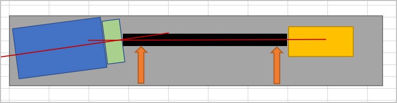
The idea of using cheap black pipe is simply to make the bar stiff without adding unnecessary weight which might deflect and affect the alignment.

I will make the assumption here that others already know how to align a tailstock. This is not about that task. This is about aligning (or testing the alignment of) the spindle to the bed.

I believe said alignment requires a cut at both ends of a test bar. Ideally, the center section of the bar is of smaller OD than the ends so that the tool bit can move end to end without cutting the center. But this is not a requirement.

Such a bar is NOT mounted in centers. It can be mounted in the spindle taper or in jaws. In either case, a cut must be made at both ends to true the axis of the bar to the axis of the spindle. However, the extent to which the axis of the bed is misaligned with the axis of the spindle will affect the OD of the two ends. It is this difference that is used to test and to determine the alignment.

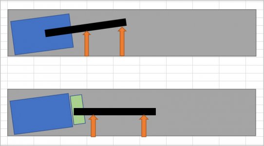
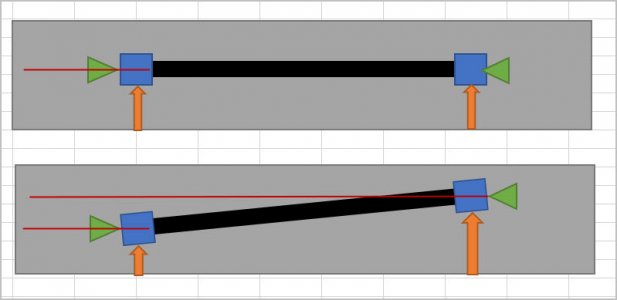
@PeterT prepared some drawings to demonstrate the evaluation and I have copied his post here.

I'm talking about a shop made alignment dumb bell either from solid, or from something like a section of tubing plus separate ends to economize on material. All you need is Loctite to bond the ends. Tubing is actually desirable because it doesn't need to be cut (stress relief) & has plenty of rigidity for this application. Once you have end blanks either center drilled & slightly oversize OD ends, you mount between centers (not a chuck or collet) & take a skim cut over the OD. Preserve that infeed setting exactly, flip the bar & repeat skim cut on other side. They are now centered and parallel. Indicating on the HS side & comparing that to the TS side will indicate in/out & up/down of the TS center. No cutting is ever required beyond making the test bar.

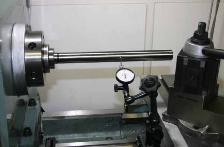
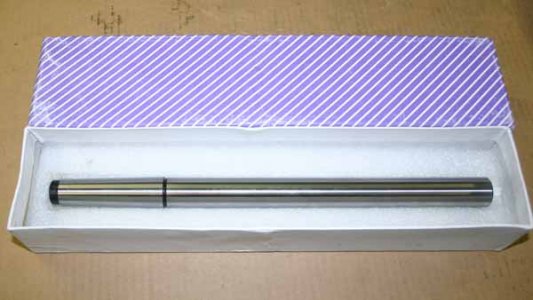
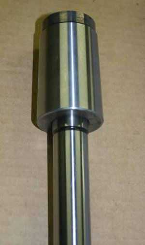
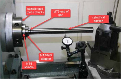
To check spindle alignment relative to bed, the best method I know of is a precision MT taper / parallel bar. The one I bought is MT3 so I use my MT5/MT3 ground adapter that came with the lathe. You can also use this to stick in the tail stock MT socket & do some referencing there independent of the headstock. If you have a completely parallel test bar, it must be gripped by a chuck or something & you introduce potential errors.

I'm not sure I agree with Peter's post in total but usually I find that is because I didn't understand what he meant. ;)

In my experience , the whole point of chucking the bar is to true it to the chuck axis. To do this cuts MUST be made. Said cuts will result in a perfect cylinder if the axis is aligned or a cone if they are not. Furthermore, measurements can be made at the tops and fronts of the bar to determine any angularity.

Ive always found it wasteful to use a solid bar because fresh cuts must be made each time the bar is used. @Brent H has apparently had the same experience. Hence my idea of a pipe and sleeves very similar to what @YotaBota suggests, but not mounted on centers. Again, to test head to bed alignment the bar must not be constrained to the tailstock.

I like the idea of locktite to hold the collars on, but I'm thinking screw on would be better at the far end and some kind of locking taper or even bolted connection at the near end. I'd like the replacement to be easy when they get too small.
 

Susquatch

Ultra Member
Administrator
Moderator
Premium Member
@PeterT @YYCHM .

Remember that the bar is not mounted in the tailstock. I don't want the bar to be turned around because I need to find the misalignment. That is done by measuring the difference caused by the misalignment. If it's parallel, it's perfect. Again, a fresh cut must be made each time the bar is used and each time the head alignment is adjusted.
 

PeterT

Ultra Member
Premium Member
I'm not sure I agree with Peter's post in total but usually I find that is because I didn't understand what he meant.

Maybe there are 2 separate issues in your question so lets deal with aligning headstock to ways first. It does not involve the dumb bell bar.
Test bar has MT taper on one end which engages spindle MT socket. A DTI is attached to mag base attached to saddle. DTI runs along the cylindrical portion of test bar. It detects in/out and/or up/down represented by orange arrow length. The reason why I think introducing any kind of work holding part like a chuck is because the chuck mount + jaws + test bar are potential collective error sources. I cant draw it proper but that's what lower sketch represents. DTI says head is aligned but it could be a combination of factors which masks or exaggerates. So far so good?
 

Attachments

  • IMG_5727_edited-1.jpg
    IMG_5727_edited-1.jpg
    38.7 KB · Views: 15
  • IMG_5728_edited-1.jpg
    IMG_5728_edited-1.jpg
    44 KB · Views: 15
  • IMG_5729_edited-1.jpg
    IMG_5729_edited-1.jpg
    28.4 KB · Views: 12
  • SNAG-2022-02-12 9.12.52 PM.jpg
    SNAG-2022-02-12 9.12.52 PM.jpg
    38.2 KB · Views: 14
Last edited:

PeterT

Ultra Member
Premium Member
The reason why the HS must first be aligned to ways independent of TS is you could have 2 misalignment problems masking the problem. HS is cocked at angle. TS is off center, displaced to rear. But the centers are aligned & DTI would not register change. Nobody would test a lathe this way but just demonstrates trick geometry.

So many advocate Step-1 as chucking a big bar of aluminum (with no TS support of course), the bar is cantilevered. By spinning & turning the stock we introduce taper in the test bar if the HS is misaligned. Measure the inner & outer diameters shows us what direction HS is cocked & by how much. The chuck/jaws/mount don't factor because this is a rotating environment. But the downsides (in my mind) are

- you are somewhat limited by how much material stick out. A 2" diameter bar at say 3:1 is only 6" long. So you can only detect angular deviation to that length. Is 0.001 per 6" good enough? That's for you to decide. Are you absolutely positive a 0.001" larger diameter measurement at the outboard end wasn't just material beam deflection? How about surface finish? How would you disseminate if the HS was misaligned in pure yaw vs. pointed up/down in the bed. The resultant taper is a combined effect of both issues.

- So you make a sensitive, remedial lathe tweak to adjust HS. Now rinse & repeat the entire cutting procedure.

The test bar seems so much easier to me. Its precision ground, supposedly within tenths if you can verify it. Plug it into the spindle & DTI measure.
 

Attachments

  • SNAG-2022-02-12 9.29.05 PM.jpg
    SNAG-2022-02-12 9.29.05 PM.jpg
    28.2 KB · Views: 6
Last edited:

PeterT

Ultra Member
Premium Member
Some people have different spindles & might be wondering about the MT. I've annotated my lathe. The spindle is an MT5 socket.
 

Attachments

  • EDT-2022-02-12 9.55.36 PM.jpg
    EDT-2022-02-12 9.55.36 PM.jpg
    68.9 KB · Views: 23

Susquatch

Ultra Member
Administrator
Moderator
Premium Member
I believe I understand you now Peter.

Regarding part 1. I guess I just don't trust a taper to be that accurate. I'd be chasing my tail if not. But a very light fresh cut will be concentric and trust worthy.

Edit - "repeatably accurate" meaning - can it be removed and re-installed such that it will be within a tenth or so each and every time?

Regarding part 2. I did some math regarding beam deflection. At 18" with 1.5" black pipe, it isn't enough to worry about and won't materially affect the measurement or the alignment. I was going to do some actual deflection measurements at 24" to confirm this view. Maybe I will do that tomorrow if I get the opportunity.
 
Last edited:

Susquatch

Ultra Member
Administrator
Moderator
Premium Member
Btw @PeterT, I believe I've said this before, but I really do admire your ability to whip together drawings to support your descriptions. You do a great job of that and I'm jealous!
 

PeterT

Ultra Member
Premium Member
18" on 1.5" diameter is a 10:1 (L to D) stick-out ratio. If we buy into conventional rule of thumb ~ 3:1-ish for steel, 4+ should consider tailstock support, 7+ consider steady (something along those lines?)
I'm not sure if the guidance is relaxed for super thin skim cuts. But 10 is a lot don't you think?

I've never turned black pipe so I can't speak with any experience there. But I can envision other factors creeping in. Deflection equations assume a perfect, homogeneous material. But most metals release internal stresses, some much worse than others & a function of skin depth. So I envision that if the unsupported end self-deflects after cutting & goes 'up-banana' by 0.001" the diameter difference would be 2X = 0.002" apparent diameter difference assuming a perfectly parallel cut & mirror finish. To what degree its happening, that's harder to know. I've had to abandon a few grades of supposedly stable hot rolled materials over SP (stress proof) for post deflection over only 6" & that part was TS supported.

I also envision (but have no idea how to calculate) dynamic whip. To the extent the material can deflect down under it's own weight & is magnified once it comes up to rpm. Longer stickout & lower modulus are worse. So again, any measured diameter reduction has nothing to do with HS alignment & everything to do with materials & cutting influence.

The way I think of the typical (D) spindle (and maybe its wrong) our entire chuck setup is wholly dependent on the 4" vertical face & 0.5" nose taper for its alignment. These surfaces are factory ground at the same setup & I believe so is the internal MT taper. We cant use the vertical face or nose for HS alignment, but why would I dismiss 4-5" of accurate MT socket length coincident with the axis in question by just inserting an accurately ground test bar that involves no other extraneous factors?
 

Mcgyver

Ultra Member
Theoretical discussion, or a particular problem that needs solving?

Several thoughts. This assumes correct headstock alignment from the factory, sadly in this day and age perhaps a necessary qualifier rather than a given.

imo headstock misalignment is a bit of a unicorn, almost. Everybody's heard of it, no ones seen it. Any reputable manufacturer is going to achieve alignment at the factory (by scraping often). They do so to their claimed spec sheet or to a standard like Schlesingers' limits. That's it. You'd have to make a big effort the change that, not sure even a spindle bending crash would do so. On inverted V ways lathes for example, you can take them apart a hundred times, and if you don't create a burr, they will go back in exactly the same alignment as from the factory.

"but its turning a taper!". If you are getting a taper from work unsupported by the tailstock, and you haven't been in there changing the geometry, its because of bed twist and/or wear. "but I leveled the lathe!" Did you use a Starrett 199 or equivalent (few are equivalent imo)? Even if you did, concrete moves and can throuw things off such that when you are chasing sub thou accuracy, a bit of bed twist can wreck your day. Then there is wear; You level off an unworn surface, and get the bed dead straight, but the tool path isn't straight because of wear. When I have to get a longer cylinder very straight, I've learned how to tweak the TS end of the bed mounting bolts to fine tune and eliminate taper, for example. Makes you feel like the Fonz giving the juke box a smack lol. 5100 lb lathe I can take a 1/4 thou taper out with a tweak of the correct floor leveling bolt

Where you do need to align the headstock is with reconditioning work. After a bed is scraped (or ground) everything mating with it must be scraped to it. The geometry will have changed and you must mate the headstock (and saddle and TS) to the new bed geometry, as well as achieve alignment between them, the bed and each other.

Lathe makers use precision test bars for expediency, however they are not for us. First, you'll go broke buying them for all the lathes you'll touch in our lifetime but mainly they introduce error potential between the bar and spindle.

What most guys do, and imo the best way, is to make or procure a really accuracy ground cylinder. to a tenth. On small lathes I've used 1/4" dowel pin but something about the shape and size of a cylindrical sq is about right for a regular size lathe. Chuck it however you like - 3 jaw is fine. Its alignment does not matter.

Then indicate it at plane near the chuck, and then at the extreme end away from the chuck. index the spindle 180 degrees and repeat. Use a good quality tenths indicator. By comparing the measurements you can very accurately determine misalignment. See diagram below - when a=b you are aligned. I make tables and record each set of data points so I can see how I'm progressing (or not!) and it can sometimes take a frightful number of iterations. To get things to the correct Schlesinger limit, its a function of deviation and length, the cylinder doesn't have to be as long if the measuring ability is more accurate. With a long dowel pin (longer than that in the photo) I got the little lathe in Schlesinger limit alignment. (I did however prove out the accuracy of the pin first)

Wear will mess you up, but there shouldn't be any working on HS alignment as the usual reason for doing so is scraping into a freshly scraped/ground bed.

Lastly, when indicating, its better to use some sort of sweep tool, i.e. the indicator on a spindle so can sweep the bar. Just dragging the carriage along is sub-optimal; for example if you are aligning in Z/Y, you'd don't know if you are right on top of the cylinder as you move along it as the HS could be out in Z/X. The second photo shows a sweep tool mounted on my alignment tool and in use scraping in a small headstock. In this photo its set up the sweep in the Z/Y plane.


MWZ_1412-1300x864.JPG


MWZ_2539 bw-1300x864.jpg
 

Susquatch

Ultra Member
Administrator
Moderator
Premium Member
A few things @PeterT .

I agree with your concerns. Keep in mind that I have not done this yet. I'm just brainstorming the concept. To date I've done exactly what @Brent H did. I just don't like wasting a good bar like that.

My rough math says the rigidity of the black pipe should be ok with the following caveats:

First, not cutting the black pipe, just the two aluminum collars.

Second, no high speed, and none required. But I'm gunna noodle ways to do it without turning the lathe on. Eg - Doesn't have to be a wide collar. Could be a very thin washer you can turn by hand with a free wheeling chuck. (this might introduce some bias though.)

Third, the reasons for 1.5" black pipe are multiple: to have some pipe inside the spindle to help everything stay in place, and because it's about the stiffest stock you can buy for the weight and because it's dirt cheap.

Fourth, you are absolutely right, no heavy cuts allowed. If the tool exerts any significant force on the aluminium collar at all, it won't work.

But I'm gunna chuck up a pipe today and measure all that so we can know for sure.

The only reason to increase the length is to improve the precision. Maybe that is chasing a false goal though.
 

Susquatch

Ultra Member
Administrator
Moderator
Premium Member
Theoretical discussion, or a particular problem that needs solving?

Several thoughts. This assumes correct headstock alignment from the factory, sadly in this day and age perhaps a necessary qualifier rather than a given.

imo headstock misalignment is a bit of a unicorn, almost. Everybody's heard of it, no ones seen it. Any reputable manufacturer is going to achieve alignment at the factory (by scraping often). They do so to their claimed spec sheet or to a standard like Schlesingers' limits. That's it. You'd have to make a big effort the change that, not sure even a spindle bending crash would do so. On inverted V ways lathes for example, you can take them apart a hundred times, and if you don't create a burr, they will go back in exactly the same alignment as from the factory.

"but its turning a taper!". If you are getting a taper from work unsupported by the tailstock, and you haven't been in there changing the geometry, its because of bed twist and/or wear. "but I leveled the lathe!" Did you use a Starrett 199 or equivalent (few are equivalent imo)? Even if you did, concrete moves and can through things off such that when you chasing sub thou accuracy, a bed of bed twist can wreck your day. There there is wear; You level off an unworn surface, and the bed dead straight, but the tool path isn't straight because of wear. When I have to get a longer cylinder very straight, I've learned how to tweak the TS end of the bed mounting bolts to fine tune and eliminate taper, for example. Makes you feel like the Fonz giving the juke box a smack lol. 5100 lb lathe I can take a 1/4 thou taper out with a tweak of the correct floor leveling bolt

Where you do need to align the headstock is with reconditioning work. After a bed is scraped (or ground) everything mating with it must be scraped to it. The geometry will have changed and you must mate the headstock (and saddle and TS) to the new bed geometry, as well as achieve alignment between them, the bed and each other.

Lathe makers use precision test bars for expediency, however they are not for us. First, you'll go broke buying them for all the lathes you'll touch in our lifetime but mainly they introduce error potential between the bar and spindle.

What most guys do, and imo the best way, is to make or procure a really accuracy ground cylinder. to a tenth. On small lathes I've used 1/4" dowel pin but something about the shape and size of a cylindrical sq is about right for a regular size lathe. Chuck it however you like - 3 jaw is fine. Its alignment does not matter. To get things to the correct Schlesinger limit, its a function of deviation and length, the cylinder doesn't have to be as long if the measuring ability is more accurate. With a long dowel pin (longer than that in the photo) I got the little lathe in Schlesinger limit alignment. (I did however prove out the accuracy of the pin first)

Then indicate it at plane near the chuck, and then at the extreme end away from the chuck. index the spindle 180 degrees and repeat. Use a good quality tenths indicator. By comparing the measurements you can very accurately determine misalignment. See diagram below - when a=b you are aligned. I make tables and record each set of data points so I can see how I'm progressing (or not!) and it can sometimes take a frightful number of iterations.

Wear will mess you up, but there shouldn't be any working on HS alignment as the usual reason for doing so is scraping into a freshly scraped/ground bed.

Lastly, when indicating, its better to use some sort of sweep tool, i.e. the indicator on a spindle so can sweep the bar. Just dragging the carriage along is sub-optimal; for example if you are aligning in Z/Y, you'd don't know if you are right on top of the cylinder as you move along it as the HS could be out in Z/X. The second photo shows a sweep tool mounted on my alignment tool and in use scraping in a small headstock. In this photo its set up the sweep in the Z/Y plane.


View attachment 21043


View attachment 21044

All excellent points @Mcgyver .

Yes, its just a theoretical discussion for now. Basically reviewing the common knowledge and looking for potential improvements. The goal is continuous improvement. Again, maybe a false goal.

As an incredible coincidence, I just finished reading Schlesingers book last night! Many of the principles are the same or similar to the design for manufacturing used in the Auto industry. There is no point designing something that has more precision than needed, or that is possible, yet tolerances do stack up.

My lathe has six leveling screws. The head bolts to the end of the bed - not on top of it. Aligning the head to the bed is a part of normal setup.

Edit - Actually, this last point isn't technically correct. The head bolts to the bed frame and the end of the ways but doesn't sit on them.
 
Last edited:

RobinHood

Ultra Member
Premium Member
The head bolts to the bed frame and the end of the ways but doesn't sit on them.
My Colchester and CMT are both like that.

The only adjustment (without getting the scraping tools out to correct for nod) is in yaw when using the HS adjusters. This is where cutting a test bar comes in. Factories probably get nod close enough to parallel.

I suppose adjusting the nod is relatively simple since there are usually 4 levelling feet at the HS end to “bend” the bed sufficiently right at the spindle nose to align the spindle axis in nod to the bed. Yaw is taken care of by the lateral adjustment screws.
 

Susquatch

Ultra Member
Administrator
Moderator
Premium Member
My Colchester and CMT are both like that.

The only adjustment (without getting the scraping tools out to correct for nod) is in yaw when using the HS adjusters. This is where cutting a test bar comes in. Factories probably get nod close enough to parallel.

I suppose adjusting the nod is relatively simple since there are usually 4 levelling feet at the HS end to “bend” the bed sufficiently right at the spindle nose to align the spindle axis in nod to the bed. Yaw is taken care of by the lateral adjustment screws.

Totally agree. That is exactly how mine is adjusted too.
 

Susquatch

Ultra Member
Administrator
Moderator
Premium Member
I did some quick measurements to see what we are really talking about with the black pipe. Turns out I don't have any 1.5 pipe right now. I'll have to see if any neighbours have a scrap piece. I do have 1-1/4. The OD on this is 1.325.

At 24", the 1-1/4 pipe bends almost exactly 1 thou under its own weight. I just used another 24" piece at the half way point. No math required. It is what it is.

I tried it at various degrees to see if the seam mattered. It does not.

This is obviously a way better number than a calculated number based on material properties and geometry. Ninetheless, it does agree more or less with the calculated number I got for the 1.5" pipe at 5 tenths.

I suppose the easiest thing to do is to take that bending into account in the alignment math. But I'd do a more precise measurement for that.

More later. Gotta go play with grandkids.
 

PeterT

Ultra Member
Premium Member
First, not cutting the black pipe, just the two aluminum collars.

So to keep things logical, everything discussed thus far pertains to Step-1: independently aligning the HS to ways which has nothing to do with TS position. It's out of the picture at this point.
It looks like you have switched gears & now talking about Step-2: aligning the TS to an established aligned HS setup. You can't skip Step-1 & go directly to Step-2. At least I think that's what you are talking about because that is the only purpose of the dumb bell style test bar, be it cut from solid or a shop made bar or purchased Edge bar if so inclined. The bar itself in this application is just a carrier, all it has to be is stiff & distortion free over time so almost anything will do. An aluminum tube is about as cheap as you can get. It weighs less & stiffness : weight ratio is probably sufficient for this purpose, but your mileage may vary. The important bits are the cut & centered dumb bell ends.

So assuming we are now talking about Step-2, here is re-work of my original sketch. It shows exaggerated TS is displaced away from spindle axis. The dumb bell surfaces are the reference datums for DTI ball which stays fixed on apron for test. Any needle discrepancy (orange arrow length) shows the in/out of TS. You can also do this vertical plane to see if TS is above/below although this is less critical to taper cutting. You can also do this with TS barrel retracted, extended, locked, unlocked to see the many exciting ways our machines can vary LOL.

If you want to get a bit more geeky, even the center drill method can be error prone at larger angles. Why? because the 60-deg dead center point will 'find a way' to engage the 60-deg cone, but its not truly coincident with the axis intersection of the dumb bell. If you want to overcome that, it's best to drill the centers with (forgot the name, parabolic maybe?) center drills which impart a curve profile to center drill so dead center is tangentially in contact. I think these were used more for taper turning for this reason. But I suspect outside the scope of discussion.
 

Attachments

  • SNAG-2022-02-13 10.33.25 AM.jpg
    SNAG-2022-02-13 10.33.25 AM.jpg
    39.2 KB · Views: 4

Susquatch

Ultra Member
Administrator
Moderator
Premium Member
So to keep things logical, everything discussed thus far pertains to Step-1: independently aligning the HS to ways which has nothing to do with TS position. It's out of the picture at this point.
It looks like you have switched gears & now talking about Step-2: aligning the TS to an established aligned HS setup. You can't skip Step-1 & go directly to Step-2. At least I think that's what you are talking about because that is the only purpose of the dumb bell style test bar, be it cut from solid or a shop made bar or purchased Edge bar if so inclined. The bar itself in this application is just a carrier, all it has to be is stiff & distortion free over time so almost anything will do. An aluminum tube is about as cheap as you can get. It weighs less & stiffness : weight ratio is probably sufficient for this purpose, but your mileage may vary. The important bits are the cut & centered dumb bell ends.

So assuming we are now talking about Step-2, here is re-work of my original sketch. It shows exaggerated TS is displaced away from spindle axis. The dumb bell surfaces are the reference datums for DTI ball which stays fixed on apron for test. Any needle discrepancy (orange arrow length) shows the in/out of TS. You can also do this vertical plane to see if TS is above/below although this is less critical to taper cutting. You can also do this with TS barrel retracted, extended, locked, unlocked to see the many exciting ways our machines can vary LOL.

If you want to get a bit more geeky, even the center drill method can be error prone at larger angles. Why? because the 60-deg dead center point will 'find a way' to engage the 60-deg cone, but its not truly coincident with the axis intersection of the dumb bell. If you want to overcome that, it's best to drill the centers with (forgot the name, parabolic maybe?) center drills which impart a curve profile to center drill so dead center is tangentially in contact. I think these were used more for taper turning for this reason. But I suspect outside the scope of discussion.

Nope, am more or less STRICTLY talking about step 1. Step 2 is easy stuff. Any discussion about step 2 is only an effort to avoid duplication. Cutting is only required in Step 1, not 2.

Yes, I recognize that you are doing it without cutting, but I am not convinced (yet anyway) that this can be done. In my opinion, doing it without cutting would require that your MT5 (plus adapters) is ALWAYS concentric to the spindle but I doubt that it is. You will have to convince me of that or perhaps I will have to convince myself! LOL!

The purpose of my dumbbell (as you call it) is to keep the amount of cutting to a minimum and subsequent measurements to a closely constrained location. Nothing more or less.

To avoid confusion, let's stick to the step one piece of this until the horse is dead and further flogging is pointless.

I'll remember to come back to your thoughts on step 2 when that time comes.
 

YotaBota

Mike
Premium Member
This has gotten interesting but also kinda deep.
So, I do all the checks and balances to find my HS is nodding and/or yawing,,,, then what? I haven't found any HS adjustments for my machine, SM1120, and as a hobbiest I won't be spending a zillion dollars having it scraped to get under .001 (or what ever) in the 20" of bed I have.
Are there any options to realign the V bed HS short of scraping?
I don't imagine the majority of us have machines big enough or accurate enough to warrant those types of adjustments let alone the need. My guess would be the Myford/Atlas flat beds have the advantage in ease of adjustments over the V bed machines, go Flatbed go :D
 

Susquatch

Ultra Member
Administrator
Moderator
Premium Member
This has gotten interesting but also kinda deep.
So, I do all the checks and balances to find my HS is nodding and/or yawing,,,, then what? I haven't found any HS adjustments for my machine, SM1120, and as a hobbiest I won't be spending a zillion dollars having it scraped to get under .001 (or what ever) in the 20" of bed I have.
Are there any options to realign the V bed HS short of scraping?
I don't imagine the majority of us have machines big enough or accurate enough to warrant those types of adjustments let alone the need. My guess would be the Myford/Atlas flat beds have the advantage in ease of adjustments over the V bed machines, go Flatbed go :D
My lathe has 6 floor screws. They are used to exert pressure under the head to make minute alignment changes.

I would think some similar adjustment is possible on any lathe. Even one with just 4 feet.

That said, one can go crazy chasing unrealistic goals. Sonetimes good enough.... really is!

Lastly, there are usually numerous ways to accomplish a goal.
 

RobinHood

Ultra Member
Premium Member
I haven't found any HS adjustments for my machine, SM1120, and as a hobbiest I won't be spending a zillion dollars having it scraped to get under .001 (or what ever) in the 20" of bed I have.
This was done for you at the factory.

When I cleaned up my SM1120 (and the SM1340 for that matter), the original blueing and scraping was still on the mating surfaces between the HS and the ground bed (both on the inverted V and the flat).

As you observe, if you want to / need to change the HS to bed alignment on those machines, you need to scrape them. Once aligned, there should be no reason for that to ever change in normal use.
 

Mcgyver

Ultra Member
This has gotten interesting but also kinda deep.
So, I do all the checks and balances to find my HS is nodding and/or yawing,,,, then what? I haven't found any HS adjustments for my machine, SM1120, and as a hobbiest I won't be spending a zillion dollars having it scraped to get under .001 (or what ever) in the 20" of bed I have.
Are there any options to realign the V bed HS short of scraping?
I don't imagine the majority of us have machines big enough or accurate enough to warrant those types of adjustments let alone the need. My guess would be the Myford/Atlas flat beds have the advantage in ease of adjustments over the V bed machines, go Flatbed go :D

its got to get a little deep so that people can understand what is really going on. If someone really does need a headstock alignment (a unicorn) its a really big job and you're going to pay a lot or have to learn how to scrap, no matter how much the person doesn't want to. However....if its a decently made lathe (a SM definitly is), its almost for sure not a head stock alignment issue, no matter how much it appears to be so (I hedge with the "almost" just in case the earth has come off its axis and weirdness is everywhere).

And we get things to tenth over 2 feet not a thou :D
 
Last edited:
Top