Hi All,
Moving on.
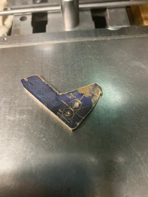
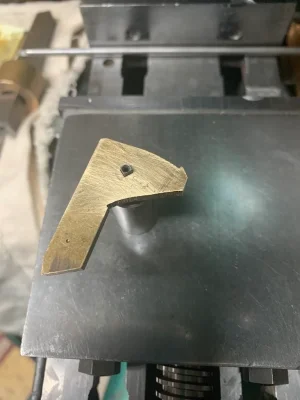
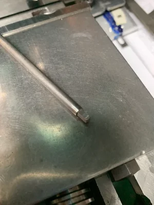
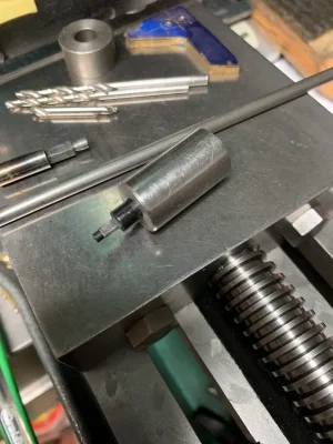
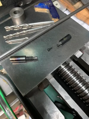
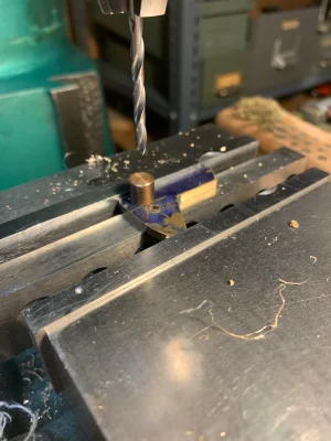
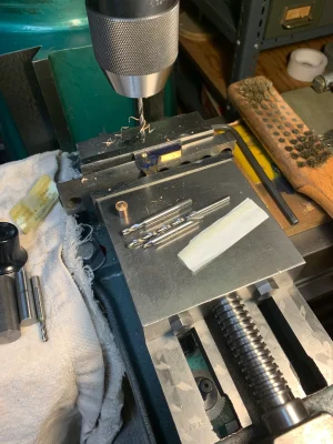
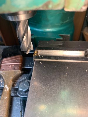
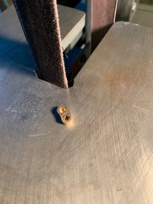
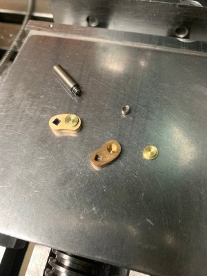
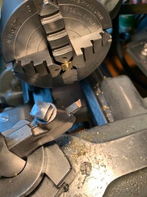
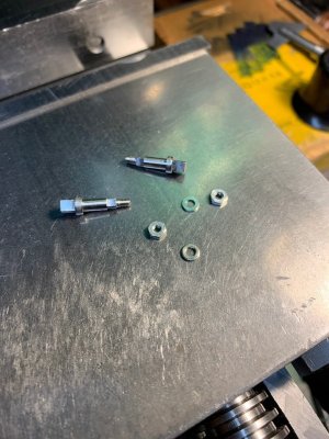
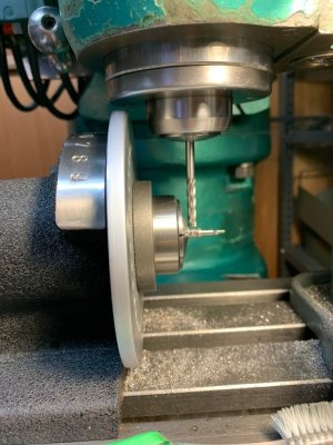
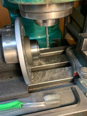
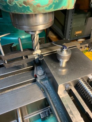
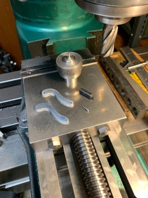
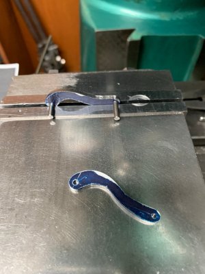
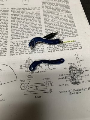
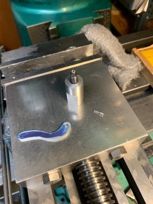
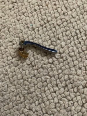
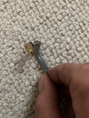
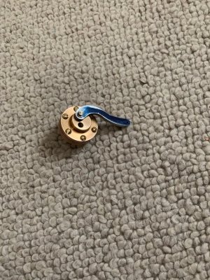
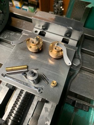
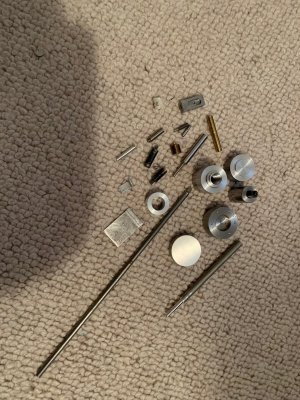
The partially made valve handles shown are not Superscale but I liked the look so I decided to make up something in that style. They were "eyeballed" from the Superscale photo posted early in the thread.
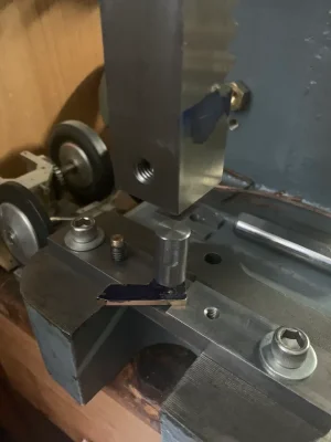
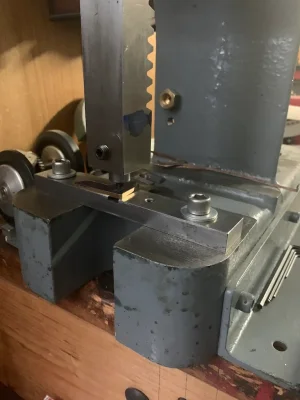
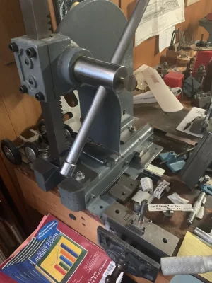
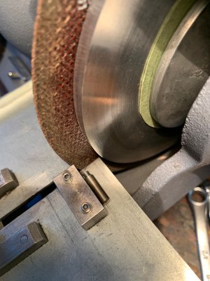
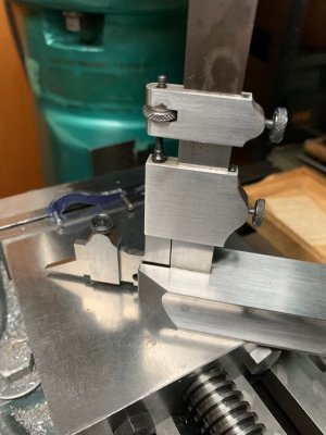
Construction wise, they were first roughed out on the bandsaw and then contoured on the belt sander. Just careful work but it left a lot of grit to clean up.
Moving on.
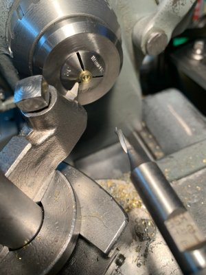
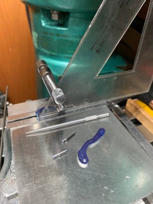
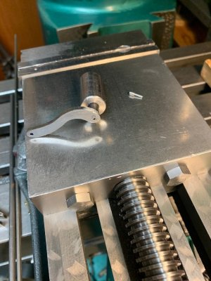
The partially made valve handles shown are not Superscale but I liked the look so I decided to make up something in that style. They were "eyeballed" from the Superscale photo posted early in the thread.
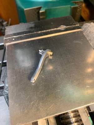
Construction wise, they were first roughed out on the bandsaw and then contoured on the belt sander. Just careful work but it left a lot of grit to clean up.