• Scam Alert. Members are reminded to NOT send money to buy anything. Don't buy things remote and have it shipped - go get it yourself, pay in person, and take your equipment with you. Scammers have burned people on this forum. Urgency, secrecy, excuses, selling for friend, newish members, FUD, are RED FLAGS. A video conference call is not adequate assurance. Face to face interactions are required. Please report suspicions to the forum admins. Stay Safe - anyone can get scammed.

It Looks So Easy and Straightforward ON Paper But...

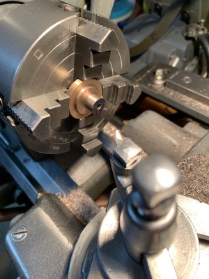
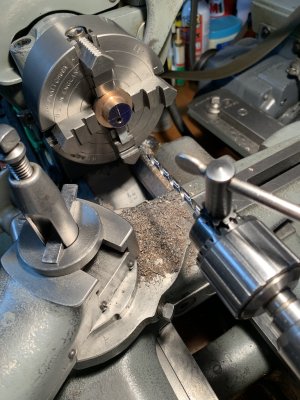
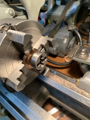
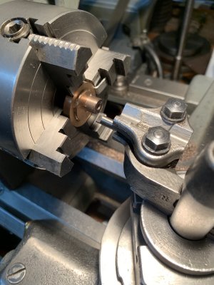
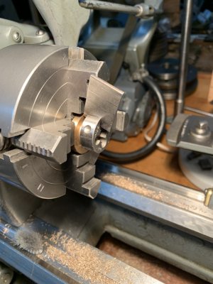
I don't quite follow why you could not use your jaws orientated to the smaller diameter with a parallel or sacrificial backstop material. I see the way you have it you get the benefit of the jaws as a back stop, but don't you risk drilling into it? (assuming its a through hole)?

This is why I like chuck depth stops. I just wish they were not so expensive.

Now if I had a 3D printer and some way to make them flat to say a half thou......
 
Hi Peter,

No, you won't drill into the backing jaws as the offset steam through hole intersects with the front recess which you can see in the first photo and in the x-section of the print. Also, the small diameter (which is the rear face of the half body sticking outwards has many more other machining operations yet to do on it.
 
Last edited:
Hi All,

More test work before I can proceed any further.

Part of the problem of finding an alternative way to thread the spigot 1/8-27 NPT and not use a threading die would be if I could single point the thread. This would reduce the gripping and torque pressure on the valve body half considerably but not reduce it to the level which I would totally be comfortable with. However, after thinking about it further, I came up with an additional two tricks which, in conjunction with single pointing, would get the job done.

On my lathe, the gearbox is set up to thread 26 TPI or 28 TPI but not 27 TPI. However, there is a sheet from SB which shows how this can be done if you change one gear in the gear train on the gearbox input shaft. I thought no go as SB is out of business and I don't have that special gear (or stop everything and wait while I have one printed up).

But I do have it!!

Ever since the lathe was purchased second hand back in 1976, I have had a couple of gears laying around which I never was able to figure out where they came from or what they were intended for but now I know what one of them is. I couldn't believe it.

After resetting the gear train to the gearbox input shaft, I wasn't about to plunge ahead without trying the new gear train out on a test piece first as I never have had luck like this.

But the results speak for themselves. Just want you to note again how many (fancy $$) tools are involved to do the most straightforward threading. And the actual setup on the part won't be quite so straightforward.
 

Attachments

  • 190 The Test Piece Threading Setup.jpg
    190 The Test Piece Threading Setup.jpg
    304.3 KB · Views: 5
  • 191 The Test Thread is 27 TPI.jpg
    191 The Test Thread is 27 TPI.jpg
    187.1 KB · Views: 5
Adjusting a center punch divit to be in the center line of the lathe with a 4 Jaw is definitely difficult. Way way back, I think it was a Model Engineer's Workshop article that showed how to make a tool to do this for not a lot of money.

The ratio is 1:10 so if the cross slide is properly centered on axis then once the 4 jaw is adjusted to move the center punch hole to the lathe turning axis the other end of the point doesn't move. To center his I just tweaked the 4 jaw until I saw the long end move less than 0.010". or thereabouts. There's no guarantee that my center punch divit wasn't out by 0.001" or so either.

I don't remember what project I used this four but the discussion on finding an offset point on something held in the chuck reminded me I had made this tool. I think the late Robert Grauman from Spruce Grove many have given me the little ball that was soldered onto the rod. It's been at least 20 years and more likely 25.

1721197725658.png
 
Hi All,

Moving on with the actual machining.

The very tense part came with the eccentric machining. No matter what tool bit I used, it put a lot of force on the workpiece (as one was constantly turning into a corner) and at one point the workpiece was definitely starting to wobble so everything was stopped and the valve body recentered. Fortunately, since the valve body seats square on the flat face of the 4 jaw step, I only had to use the indicator to correct runout radially. If it had been in two directions (i.e. unsupported wobble) good luck as Mcgyver says trying to dial that in (in two planes 90 degrees apart) to high precision.

Even as it was I was sweating bullets.

In desperation, I reverted to my instincts as what to do and to what had worked before in such a situation. A slim, long nose radius HSS tool was ground up as seen in the last photo and it finished the job perfectly. No chatter, very little force even in a corner and it left an excellent finish (second photo). However, one must be aware to keep the tool sharp and to take light cuts.

I don't have a lot of cutters ground like this (I should make more) as it takes a lot of grinding on a tool blank to produce the slim outline. All tool bit relief angles were ground 10 degrees (top, side and front) as per what the SB tool bit grinding specification sheet generally recommends. SB know their lathes and their recommendations have always worked for me (irregardless of the material being turned). I also have their tool bit grinding block which helps.
 

Attachments

  • 194The Narrow Nose Turning and Facing Toolbit Used.jpg
    194The Narrow Nose Turning and Facing Toolbit Used.jpg
    244.2 KB · Views: 5
  • 193 After Eccentric Turning the Steam Inlet Spigot.jpeg
    193 After Eccentric Turning the Steam Inlet Spigot.jpeg
    215.5 KB · Views: 4
  • 192 After Drilling the Steam Inlet.jpg
    192 After Drilling the Steam Inlet.jpg
    303.5 KB · Views: 5
Last edited:
Hi All,

Preparing to thread the spigot 1/8 NPT.

I spent an entire week preparing the various possible toolbits which could be used.

The spigot threading arrangement here is rather unique as with the part (spigot) being recessed within the 4 jaw jaws, one needs to use an internal threading tool to have the necessary clearance but at the same time one is threading an external thread. This means that any internal threading tool used has to have a reverse form to a normal internal threading tool. It is insane but...

Another issue here is we are threading up to a shoulder and I need the thread to end as close as humanly possible to the shoulder. This makes the use of an offset 60 degree thread form necessary. The requirements to produce all of the threading tool bits seen in the photo are not straight forward and require many tooling fixtures to be made or have on hand.

If you think you know everything there is to know about threading, you should take a look at Martin Cleeve's publication entitled "Thread Cutting in the Lathe" (A MAP publication).
 

Attachments

  • 195 All of the Threading Tool Bits which Could Be Used to Form the NPT Thread on the Spigot.jpg
    195 All of the Threading Tool Bits which Could Be Used to Form the NPT Thread on the Spigot.jpg
    368 KB · Views: 6
If you are grinding your own cutters, can you make one to reverse thread, starting from the shoulder recess & away?
 
Yes, you could do it that way but you would still need to make the offset 60 degree cutter to start as close to the shoulder as possible. The limit, as stated by others, is 1/2 of the pitch of the thread. I do not have any shoulder recess either at the moment for strength considerations as if I have to lock the two taper threads together hard to have them steam and pressure tight, I don't want the valve to snap off at the spigot shoulder recess but I may be overthinking this.
 
Last edited:
Hi All,

Finally, to the threading operation itself.

The special made up threading tool itself had first to be set square to the spigot, set on centre height and be of the correct form. I have included just one photo to illustrate one of these operations.

I wasn't going to risk using power for the threading operation as I wanted to thread right up to the spigot shoulder with everything under my total control so I opted to turn the lathe spindle by hand. I really didn't know how well this would work but I found there was no issue when advancing the compound in very small increments of 0.001"per pass. Somewhat slow and repeating but...

After several passes, I would try the die on the thread and when the single point threading got to the point where the die would run up on the end of the thread square, I proceeded to turn the die by hand with the lathe spindle locked until, with two hands turning the die, I could not turn it any further with hand pressure.

Everything was then removed from the 4 jaw and transferred to the bench vise. My bench vise soft jaws are well beaten up so how much pressure to use? At this point I had also inserted the aluminum spacer in the front recess of the half body to prevent distortion if I needed to have a very firm non slip grip in the vise. But how to turn the die further?

The brute force approach was definitely a no go - no pliers or anything like that so one has to think out of the box here. I didn't know if it would work but I machined up a simple "thumb screw" turn plate as seen in the third photo to fit the split in the die (which by the way wasn't split as shown - again I had to do that in another special setup using an electric high speed grinder and a very thin "Dremel" cut off wheel).

But the thumb screw push plate worked and worked well minimizing torque but with just enough force to thread the NPT die down to the backing flange when small incremental advances were employed. One has to be aware that the push plate will get well beaten up in the process as the threading die will open up as threading proceeds and then lock onto the plate as the die is backed off. So, during the process, I had to mill down the end of the plate to compensate for this. The aim was to be finally able to turn the NPT die all the way home with only hand pressure. After many, many passes I am able to do this with less than a turn remaining so I left it at that.

The spigot now threads into the boiler mud ring threaded bushing and locks firmly in place with minimal thread showing but some final adjustment has been left as one will need to orient the valve body at the time of its final fitting.

There is the second valve body still to finish.

After going through all of this nonsense, I really wonder if LBSC ever actually did make these valves or only just describe it in his construction article as, surely, he would have encountered the same problems as described???.

For completeness, I have sketched up another way the machining operations could have been done (for future reference if ever I need to make any additional blowdown valves of this type), but it may be just a case of out of the frying pan and into the fire.

There is still more work to do on these valve half bodies so stay tuned.
 

Attachments

  • 203 The Finished Spigot Thread.jpg
    203 The Finished Spigot Thread.jpg
    247.5 KB · Views: 8
  • 202 Finishing the Spigot NPT.jpg
    202 Finishing the Spigot NPT.jpg
    244.8 KB · Views: 8
  • 201 The Threading Die Turn Plate.jpg
    201 The Threading Die Turn Plate.jpg
    215 KB · Views: 8
  • 200 Running Up the Threading Die in the Lathe.jpg
    200 Running Up the Threading Die in the Lathe.jpg
    222.2 KB · Views: 8
  • 199 The Hand Threading Operation.jpg
    199 The Hand Threading Operation.jpg
    242 KB · Views: 8
  • 197 Setting the Threading Toolbit Square.jpg
    197 Setting the Threading Toolbit Square.jpg
    201 KB · Views: 8
Hi All,

Just to quickly mention, with all of the above under my belt, the second valve body half spigot machining was a breeze. I was even able to use the thumb screw push plate in the 4 jaw chuck directly saving a lot of time and effort.

So now onto machine the remaining two front valve body halves. Will soon see what this involves.
 

Attachments

  • 206 Employing the Thumb Screw Push Plate.jpeg
    206 Employing the Thumb Screw Push Plate.jpeg
    180.5 KB · Views: 6
  • 208 The Two Valve Half Body's After Machining.jpeg
    208 The Two Valve Half Body's After Machining.jpeg
    202.3 KB · Views: 6
Looks like you are getting a lot of productive shop in. Funny how getting tooled up and ready for the job takes so much more time than the actual task.
Really enjoying following along and looking forward to seeing it all come together and doing it's thing. :cool:
 
Hi Don,

And to add to your comment, having really sharp cutting tools. Probably up to 50% of the issues I have had in the home shop over the decades are not having sharp enough cutting tools.

Don't get me started on that topic.
 
Hi All,

Moving on to the front half valve body machining.

On the initial setup, everything is a straight forward concentric turning operation so I did not take any photos here.

However, sometimes I just do things to prove that I can do it, so this involved a thin slicing operation on a very short piece of bronze that I was not going to let go to waste. This is a much more difficult alternative to the bandsaw method described here in another thread and will really test your hacksaw skills.

Some notes. Use only soft jaws for this operation and keep them clean. Set the part, thickness wise, square between the vise jaws and tighten firmly but without excessive pressure just enough to prevent the work rotating or worse slipping out under the cutting action. How tight is basically through experience.

One needs to hold the part central between the vise jaws and not at the ends. The hacksaw needs to have a fine tooth blade 24-32 tpi although I myself used a coarser tooth blade (18 TPI). The start is very important to align the blade and take very light cuts, with very little hand pressure and complete saw control as the last thing you want is for the blade to jump off the part and gouge the machined end of the work.

Patience and determination as this is going to take time. I have pictures of but have't included any "further on" photos. With the above, one can cut up to 90% through the part without the sawcut closing up and binding the blade.

When the blade starts to bind, rotate the part and start again on the uncut portion as seen in the third photo using the above technique. For the final cuts, there is a danger that the part can slip and fly out of the vise, so to prevent any damage to the part's machined surfaces, I covered the floor and vise area with rag blankets to ensure a soft landing if needed. Here one needs to take very light cuts with next to no blade pressure and check often (with finger pressure) as to whether the closed down sawcut can be pried apart. Also, clean the vise jaw area thoroughly before re-clamping the part as you don't want to see any loose particles imbedded in the work.

In the end, I could just snap the two parts apart using finger pressure only. Another pyrrhic victory.
 

Attachments

  • 210 Front Half Valve Bodies First Stage Machining Completed .jpg
    210 Front Half Valve Bodies First Stage Machining Completed .jpg
    281.9 KB · Views: 7
  • 653 Slicing Operation Complete.jpg
    653 Slicing Operation Complete.jpg
    254.9 KB · Views: 7
  • 651 Part Rotated with Start of Final Sawcut.jpg
    651 Part Rotated with Start of Final Sawcut.jpg
    262 KB · Views: 6
  • 650 Sawcut is Starting to Close on Saw Blade.jpg
    650 Sawcut is Starting to Close on Saw Blade.jpg
    263.5 KB · Views: 6
  • 647 The Start of the Slicing Operation.jpg
    647 The Start of the Slicing Operation.jpg
    280.7 KB · Views: 7
Hi All,

Proceeding with laying out the front half bodies. This is not so straight forward as described in the LBSC construction article as it requires some thought and preparation.

First, one needs a truly rectangular stout backing block which is true and square on all sides. Then one has to clamp the two body halves to the backing block such that one can set the block both in the vertical and horizontal position and then scribe centre lines fully across the face of the parts and also make offsets in both directions without any clamping interference.

Third, one needs to realize that there is a right and left hand orientation to this layout as we have a right side and left side valve. Most persons would never notice but the rear body half spigots have been offset RH and LH and the construction article doesn't really go into this.

Finally, without my trusty vernier height gauge to make things easier, the above would have been a nightmare to do accurately any other way.

The photos shown are not always presented in sequential order but do show what one needed to do. As well, there were a few simple calculations to perform to determine exact centres and offsets from the height gauge readings.
 

Attachments

  • 211 Laying Out the First Front Half Valve Body.jpeg
    211 Laying Out the First Front Half Valve Body.jpeg
    221 KB · Views: 9
  • 212 Closeup of the Scribed Layout Lines.jpeg
    212 Closeup of the Scribed Layout Lines.jpeg
    208.3 KB · Views: 9
  • 213 The Backing Block Set Vertical.jpeg
    213 The Backing Block Set Vertical.jpeg
    389 KB · Views: 9
  • 214 Layout Lines with the Backing Block Set Vertical.jpeg
    214 Layout Lines with the Backing Block Set Vertical.jpeg
    371.8 KB · Views: 9
  • 215 An Overall Height Reading on a Valve Half Body.jpeg
    215 An Overall Height Reading on a Valve Half Body.jpeg
    432.3 KB · Views: 9
  • 216 Scribing the Upper and Lower Offset Lines.jpeg
    216 Scribing the Upper and Lower Offset Lines.jpeg
    395.9 KB · Views: 9
  • 217 After Scribing All Centre and Offset Lines.jpeg
    217 After Scribing All Centre and Offset Lines.jpeg
    406.1 KB · Views: 9
Hi All,

Next is the machining of the steam and shutoff handle passages in the two front half body halves.

It is a lot of setup work as the body halves have different features on each side where one has to reverse the part and then pick up a previously drilled through hole to complete the operation.

The parts have to be setup eccentrically as before in the 4 jaw on the two offset centres. The was done with the "wiggler" as seen previously. Then centre drill, drill undersize, counterbore a 3/16" diameter recess and finish with a 1/8" reamer all the way through for the shutoff lever passage. No matter how you proceed, it is a lot of chucking on the half body flange. As seen in the fourth photo, the half body flange is starting to show a lot of jaw marks from the tightening of the jaws. Here I should have added something earlier but I didn't.

To compensate for the above condition, the flange OD of both body halves was left 0.01" oversize as I knew this would likely happen. The last operation on these body halves is to drill and tap the six through bolt holes and then scallop the metal in between. This will effectively reduce the final OD of the valves and eliminate the jaw marks. Another lesson learned from the school of hard knocks when any softer material is chucked and you want the finished product (including the chucked sections) to be free of any evidence of machining. Also, these pressure marks will "swage" the surrounding metal (like the rear/front flange faces which I use as the square setting face on the chuck body) so they have to be monitored and if present, carefully stoned away before I mount the part in the chuck.

So, each passage requires a separate eccentric setup and then, after that, the half valve body needs to be reversed and the one drilled passage (not the reamed one) picked up as seen in the third photo. Fortunately, the drill makes a tight fit in bronze so I could re-centre it to better than 0.001" Again, this involves a lot of jaw loosening and tightening, so be aware that you are marking the work every time you do this and also make certain everything is bedded square.

One thing I did change was the LBSC article says thread 3/16"- 40 ME (model engineer) 1/8" deep as seen in the fourth photo. I made this thread 3/16"+ deep as even my ME bottoming tap has a 1/16" lead in which would only give a 1/16" full thread depth engagement! These ME threads are very fine threads to begin with and are not the strongest (if you want a stronger thread you need a coarser pitch thread - i.e. 32 TPI minimum) so having only a 1/16" full engagement was a no go. Even with a 1/8" full engagement one will have to be careful. This is another reason why I think LBSC never actually made these valves as this should have become obvious.

The last photo just shows all of the cutting tools needed just to do these "simple" steps. The wooden dowel was used, in conjunction with a small soft faced hammer, to gently tap the half body to ensure it was bedded square on the 4 jaw front face, the sharpie pen was used to mark which hole (and side) has the recess and which hole (and side) is threaded as it is easy to mix both passages up, the small triangular piece of relatively coarse broken oil stone was used to remove any and all face burrs left by machining and the 1/4" dia. aluminum rod with the 3/16" step on the end was used to check the recess depth.

PS: once your oil stone is "smeared" after stoning any soft metal, the only effective way of cleaning it again is with an ultrasonic cleaner, anything mechanical like using a file card really won't work so save up all of your broken bits and pieces and find someone who is willing and able and has the equipment... it never ends...
 

Attachments

  • 224 Just the Cutting Tools Needed.jpg
    224 Just the Cutting Tools Needed.jpg
    263.8 KB · Views: 6
  • 223 Half Body Outer Face Passages.jpg
    223 Half Body Outer Face Passages.jpg
    259.7 KB · Views: 6
  • 222 Half Body Inner Face Passages.jpg
    222 Half Body Inner Face Passages.jpg
    259 KB · Views: 6
  • 221 Threading the Steam Passage Three Sixteenths Forty TPI.jpg
    221 Threading the Steam Passage Three Sixteenths Forty TPI.jpg
    238 KB · Views: 6
  • 220 Picking Up the Steam Passage Again After Reversing the Half Body.jpg
    220 Picking Up the Steam Passage Again After Reversing the Half Body.jpg
    240.2 KB · Views: 6
  • 219 The Inner Face Steam and Handle Passages.jpeg
    219 The Inner Face Steam and Handle Passages.jpeg
    341 KB · Views: 6
  • 218 Finish Reaming the Shut Off Handle Through Hole.jpg
    218 Finish Reaming the Shut Off Handle Through Hole.jpg
    263.1 KB · Views: 6
Last edited:
Hi All,

The inside machining on both valve body halves is now complete and some new simple aligning fixtures were machined up for the next operation which is the locating and the drilling/tapping of the two half body six attachment screws. They will be 3-48 NC which is in rare use today but is just the right size here aesthetically and for strength.
 

Attachments

  • 225 All Internal Machining  Completed.jpg
    225 All Internal Machining Completed.jpg
    245.1 KB · Views: 6
  • 226 New Simple Aligning Plug Fixtures.jpg
    226 New Simple Aligning Plug Fixtures.jpg
    253.9 KB · Views: 6
  • 227 New Simple Aligning Plug Fixtures.jpg
    227 New Simple Aligning Plug Fixtures.jpg
    268.7 KB · Views: 6
Hi All,

Drilling the two half body attachment bolt holes comes next. This is another operation which is easy to describe and less easy to do without some planning and forethought even having some fancy equipment available.

First, on one half body, both of the half body centre lines had been obliterated and one of them had to be accurately re-established from the two internal offset holes (I chose the half body centre line offset 1/16"). To do this a half body was set in the milling vise with two very close fitting internal locating plugs set on my milling vise jaw top surface (which are flat ground so I can use it as an accurate straight edge and reference surface) to establish internal hole alignment and then using my trusty vernier height gauge again, I made a height reading over the locating plugs and using some simple math determined the true half body centre line height again. See the first photo. The cigarette paper shown in the photo could be slid under the locating plugs so when the vise jaws were lightly tightened I knew the two plug bodies were not touching the top surface of the vise and throwing things out of square.

The second photo shows how I can quickly centre my rotary table as needed and it is dead nuts accurate (as accurate as you make the centering plug). The centre locating plug is held in a collet and centering adjustments made with the rotary table not bolted to the table of the mill but with the centering plug inserted. All the mill's axis are then locked including the quill and finally the rotary table is firmly bolted down in a table tee slot. I test the setup by then mostly unlocking and raising the quill and bringing it back down again. Never had anything but a perfect fit.

To set the bolt circle radius, a half body was set in my previously made recessed centering plug in place of the regular centering plug to centre the part accurately in the rotary table. All backlash was taken out of the mill's table lead screw and the table's micrometer dial set to zero. The table of the mill was moved over the bolt hole circle radius using the micrometer dial. Just remember which way to turn the table handle. If you have digital you can ignore all of this but as I don't...

The rotary table was then rotated to 0 degrees, 0' and the half body part was rotated until the tip of a small centre drill tip bisected the re-scribed centre line (under magnification and good lighting). Lock everything and proceed to centre drill and drill through. Rotate 60 degrees and repeat remembering again which way to turn the rotary table handle. Fortunately, the bolt circle radius here was smaller than the centre hole on my rotary table so there was no danger of drilling into the fine finished surface of the rotary table. I pride myself that, to date, I have never made this error but it can easily happen. For some of the holes, one will need to alter the position of one or the other of the part table clamps but only do so one at a time so nothing moves.

Everything worked perfectly but I am certain there may be easier ways to do this and I probably over describe things but I will do it once and not repeat...

It gets worse so stay tuned.
 

Attachments

  • 231 Drilling a Final Half Body Bolt Hole.jpeg
    231 Drilling a Final Half Body Bolt Hole.jpeg
    523 KB · Views: 7
  • 230 Drilling the First Bolt Hole in a Body Half.jpg
    230 Drilling the First Bolt Hole in a Body Half.jpg
    300 KB · Views: 7
  • 229 Centering the Rotary Table with a Body Half.jpg
    229 Centering the Rotary Table with a Body Half.jpg
    310.3 KB · Views: 7
  • 228 Re-establishing a Half Body Centre Line from the Internal Offset Openings to Determine the...jpg
    228 Re-establishing a Half Body Centre Line from the Internal Offset Openings to Determine the...jpg
    235.1 KB · Views: 7
Hi All,

Setting the two half bodies together so they line up, then drilling and tapping through.

The first thing which I had to do was to cut off the end of one aligning plug, insert it through the two half bodies and tape over the end with masking tape to ensure it would not fall out when it was turned over with the parallel aluminum spacer/support piece which is shown in the second and third photos. The two half bodies were then carefully rotated one against the other until their OD's aligned. To ensure they stayed that way for the spotting through, drilling and tapping operations, the entire assembly was held lightly between the vise jaws and with a toolmakers clamp as shown in the fourth photo.

For the drilling and tapping operation, ensure everything is bedded square in the vise jaws and against the floor of the vise. Pick up a hole by operating the mill's table and cross feed screws and proceed to drill and tap through as seen in photos five and six. I installed the screws in the order shown in the last two photos.

When finished deburr, clean and admire your work.

PS: for completeness, all of the drilling on the front half body as described previously was done with a 3-48 NC tap drill (#47) and the spot through and drilling on the rear half body when set together with the front half body was also done with the #47 drill. This was followed (without moving anything) by a 3-48 NC clearance drill (#38) through the front half body only, the depth of drilling being controlled by the micrometer feed dial on the quill of the mill. If you have it, use it. Then the tapping through.
 

Attachments

  • 238 Three Screws Installed.jpg
    238 Three Screws Installed.jpg
    270 KB · Views: 4
  • 237 Tapping Through.jpg
    237 Tapping Through.jpg
    239.7 KB · Views: 4
  • 236 Drilling Through.jpg
    236 Drilling Through.jpg
    261.2 KB · Views: 4
  • 235 The Preparation for Drilling Through.jpeg
    235 The Preparation for Drilling Through.jpeg
    404.9 KB · Views: 4
  • 234 The Preparation for Drilling Through.jpg
    234 The Preparation for Drilling Through.jpg
    273.2 KB · Views: 4
  • 233 The Preparation for Drilling Through.jpg
    233 The Preparation for Drilling Through.jpg
    275.5 KB · Views: 4
  • 232 After Drilling.jpg
    232 After Drilling.jpg
    336.4 KB · Views: 4
  • 240 All Screws Installed.jpg
    240 All Screws Installed.jpg
    249.7 KB · Views: 4
Last edited:
Back
Top