• Scam Alert. Members are reminded to NOT send money to buy anything. Don't buy things remote and have it shipped - go get it yourself, pay in person, and take your equipment with you. Scammers have burned people on this forum. Urgency, secrecy, excuses, selling for friend, newish members, FUD, are RED FLAGS. A video conference call is not adequate assurance. Face to face interactions are required. Please report suspicions to the forum admins. Stay Safe - anyone can get scammed.

It Looks So Easy and Straightforward ON Paper But...

carrdo

Active Member
Hi All,

Maybe I complain too much but...

Here is something which looks so easy and straightforward on paper but when you get into it...

To set the scene. The drawing is of an "Everlasting" (Okadee type) live steam locomotive boiler blowdown valve (it happens to be in 3/4" scale) and the ones I am making are for a 1" scale locomotive so slightly larger.

The first operation on the bronze blanks are to machine the 1/2" OD by 5/32" deep inner pocket. The constructor (LBSC) says one can use a 1/2" D-bit or one bore it out as an alternative.

OK, but there are two things here; one is the bottom corner of the pocket has to be a sharp 90 degree corner and the other is the inner recess surface has to be truly flat (from the corner to the centre) as it acts as a flat surface against which a valve (face) operates and it has to be steam tight.

OK, I got it in the end but it was anything but straightforward.

to be continued.
 

Attachments

  • 168 The Drawing of the Boiler Blowdown Valve.jpg
    168 The Drawing of the Boiler Blowdown Valve.jpg
    304.4 KB · Views: 39
  • 169 First Machine Operations on the Half Body of an Everlast (Okadee Type) Boiler Blowdown Valve.jpg
    169 First Machine Operations on the Half Body of an Everlast (Okadee Type) Boiler Blowdown Valve.jpg
    320.7 KB · Views: 39
Hi All,

Maybe I complain too much but...

Here is something which looks so easy and straightforward on paper but when you get into it...

To set the scene. The drawing is of an "Everlasting" (Okadee type) live steam locomotive boiler blowdown valve (it happens to be in 3/4" scale) and the ones I am making are for a 1" scale locomotive so slightly larger.

The first operation on the bronze blanks are to machine the 1/2" OD by 5/32" deep inner pocket. The constructor (LBSC) says one can use a 1/2" D-bit or one bore it out as an alternative.

OK, but there are two things here; one is the bottom corner of the pocket has to be a sharp 90 degree corner and the other is the inner recess surface has to be truly flat (from the corner to the centre) as it acts as a flat surface against which a valve (face) operates and it has to be steam tight.

OK, I got it in the end but it was anything but straightforward.

to be continued.
I'm curious how you did it to get the bottom flat. D Bit or Boring? Pictures of that process?
 
Nice.
I'm not following the angled square feature. Maybe there is another section view through it but is it a broached hole or something?
Do you have any locomotive build pics of projects you're working on? We love pics!
 

Attachments

  • EDT-10-07-2024 12.05.36 AM.jpg
    EDT-10-07-2024 12.05.36 AM.jpg
    59.3 KB · Views: 7
Hello All,

Yes, I will get to what you are asking about. The square corner flat valve face was done with a boring tool which had to be modified. I have D bits but they are shop made and are not produced from HSS which is what I wanted for this job. I will use a D bit to produce a true circular through hole but that is not what we have here.

The dotted curved line which you see is the valve itself which sits against the flat face of the machined body half. The broached square hole is only in the valve body and is for the handle which operates the valve. There is the other machined body half (not yet shown) which has the bearing hole for the valve handle to operate the valve. The valve has a very light spring on it which keeps a slight pressure on the valve/valve face to keep everything bedded and steam tight. The 1/32" proud ring boss shown is the mating surface for the two body valve halves and it also has to be steam tight. It is a fine machined face joint and has to be kept that way in all subsequent machining operations.

A very simple clever design (both in full size and in model engineering) when you see it all together but it has to be made right.
 
Hi All,

OK, here are some photos of the real deal. They all happen to be for live steam locomotives but the first two photos are by far the closest to what the full size Okadee boiler blowdown valves look like. They are for 1.5"/1.6" scale model live steam locomotives and were made in lost wax castings by Superscale a California based supplier no longer in business. If you can even find a pair today, they go for north of $500.US per set (2018 price) but maybe when you see what it takes to make them as this is miniature custom made jewellery.

The remaining photos are also of 1.5" scale live steam model locomotive boiler blowdown valves of the type I am machining but in a smaller scale. Just to steal my thunder, you can see the full construction article at blogger.com Everlasting Blowdown Valve as to what is involved in making them. I am doing things slightly differently and will explain why as I come to it.

Of course you can have simpler model boiler blowdown valves that work just fine which you can make or buy from a host of live steam suppliers and save yourself a lot of grief and $$$ but why do something simple when you can do it the hard way but that is just me.
 

Attachments

  • 173.JPG
    173.JPG
    168.5 KB · Views: 16
  • 172.JPG
    172.JPG
    201.1 KB · Views: 15
  • 171.JPG
    171.JPG
    204.1 KB · Views: 16
  • 170.JPG
    170.JPG
    148.1 KB · Views: 16
Last edited:
Hi All,

Yes, I noticed that after I posted the link. Try instead Blogger.com Everlasting Blowdown Valve. I have updated the link in the previous thread.
 
To continue with the build.

Producing sharp internal 90 degree corners is not all that difficult IF you know a few tricks. The problem is that at a corner you are cutting on two surfaces simultaneously which suddenly increases the force on the cutting tool tip from two directions. This can and usually does cause the tip of the tool to dig in, to chatter or both. This is what happened on my first go round and it was so sudden that even though the work was held securely in the three jaw chuck, it caused a very visible wobble of the work in the chuck.

At the roughing out stage, the part can be rechucked without consequences but not at the finishing stage and this is what I will deal with.

A few common sense things first. It goes without saying that all tool and topslide overhang should be absolutely minimized and all machines gibs should be checked to have a very slight drag i.e. no looseness or play at all. Setting the tool further into the toolholder by only 1/4" can and will make a difference - as I initially had the tool extended too far out.

Second, tool tip geometry is important here - see the first photo - the tip of the tool has been re-ground to more of a diamond shape and other clearance angles (side - front) have been increased. Not by a lot but it makes a big difference.

Third, as I have stated elsewhere, whenever you weaken a cutting edge by increasing clearance angles, depth of cut and feed rates have to be decreased significantly. Speed, I keep fairly low, the first direct drive pulley speed of the lathe. So by depth of cut I am taking scraping passes of only 0.002"-0.003" and hand feeding the carriage very slowly (no power feed as you do not want to run into the corner!).

To produce the flat bottom pocket face, the tip of the cutting tool has to be set at exactly centre height and I mean exactly (less than 0.001" deviation). There have been many methods shown how to do this, but for this job, I used my trusty Starrett 6" vernier height gauge as seen in the last two photos. With this gauge, I can reliably estimate (consistently) to 0.0005" with the eye loup shown as the vernier graduations are very clear. One needs a truly flat reference surface but fortunately the top of the SB lathe cross slide provides this (this is why you do everything to keep it in pristine condition - it is not a tool placement/storage surface but I am guilty). And one has to mike exactly the OD of the work as well. Good lighting is essential.

Finally, there is a bit of technique involved. Start by feeding the tool into the recess OD and feed slowly until you feel a VERY SLIGHT increased resistance to further carriage movement. Stop feeding, lock the carriage then use the cross slide to feed the cutting tool straight across the bottom surface and slightly past centre. The slight increase in carriage resistance has told me that the tip of the cutting tool has now cut into the bottom surface 0.002"- 0.003". Withdraw the tool and repeat the operation until the correct diameter and depth have been achieved. Depth is not all that critical for if you go too far, you can always shave down the front face to compensate. I use a depth mike but I guess that is going a bit overboard. The secret is total control over the cutting tool tip forces and machine/tool rigidity.
 

Attachments

  • 644 Diamond Shaped Boring Tool Tip for Inside Corners.jpg
    644 Diamond Shaped Boring Tool Tip for Inside Corners.jpg
    290.1 KB · Views: 16
  • 645 Measuring with the Vernier Height Gauge.jpg
    645 Measuring with the Vernier Height Gauge.jpg
    280.9 KB · Views: 15
  • 646 Setting the Tip of the Boring Tool to the Exact Centre Height.jpg
    646 Setting the Tip of the Boring Tool to the Exact Centre Height.jpg
    262.9 KB · Views: 15
Hi All,

On to the next bit of nonsense.

The machining instructions given at this point say (and I am now paraphrasing) now reverse the part in the chuck and proceed to turn it down for the threaded boss parts which will thread into the boiler. Well, in my case, this means first machining down the back part of the valve body half to 3/4" diameter (from a 1-1/8" OD) and machine it 11/32" long. As the part has a total length of 9/16" this leaves only a 7/32"- (minus) length for the 3 jaw chuck to hold on to. Sounds very secure doesn't it! See the first two photos.

This is a disaster waiting to happen and IT WILL if you try and machine ANYTHING on the back face. But if you happen to have a lathe with a big enough collet and collet stop it might work with light cuts as the part in a collet has a 100% circular grip. But not with a 3 jaw chuck having wear as most of your 3 jaw chucks will have.

What to do? And this has never been addressed or explained anywhere. See the third photo for what I came up with. I could have gone the collet route also but lets do it the hard way again as you don't get something for nothing.

to be continued.
 

Attachments

  • 176 The Way Forward.jpg
    176 The Way Forward.jpg
    250.9 KB · Views: 13
  • 175 Doesn't That Really Look  Secure?.jpg
    175 Doesn't That Really Look Secure?.jpg
    252.3 KB · Views: 13
  • 174 A Fast and Dirty Method of Aligning a Part in the Three Jaw Which Needs to Be Reversed for...jpg
    174 A Fast and Dirty Method of Aligning a Part in the Three Jaw Which Needs to Be Reversed for...jpg
    259.6 KB · Views: 13
Last edited:
Moving ahead.

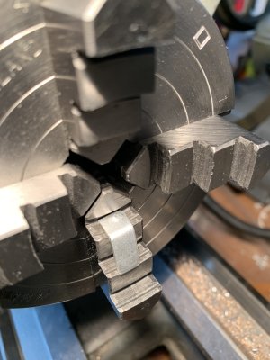
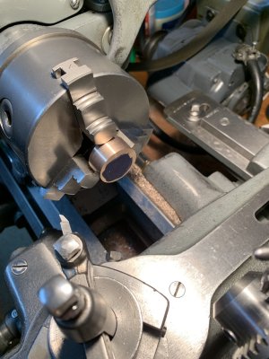
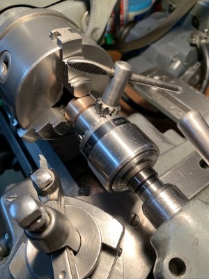
Here is the setup I came up with for holding and centering the boiler blowdown valve body reversed in your 3 jaw chuck when there is virtually nothing to hold on to and your 3 jaw chuck is well used; the jaws are likely bell mouthed and perhaps even sprung. I am deliberately using the worst chuck which I have (but it has been the most faithful one over the decades). It is a 4" diameter KTM "Put" made in Poland and purchased in the early 1970's from Swiss Instruments here in Mississauga, Ontario. Swiss instruments, at the time, was having a one time sale on this brand of chuck and at the reduced price they were selling for - I think I paid $6. Canadian for this chuck and $8 for a larger 6" diameter one which I subsequently sold. But it did have its quality control issues as the jaws have tight spots on the scroll.,

I have given this chuck its fair share of use and abuse through sheer laziness, convenience and those times when conditions became pressing.

The interesting history here is that these chucks subsequently became the Bison line of chucks after the fall of communism.

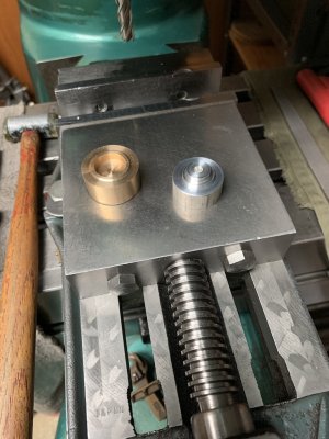
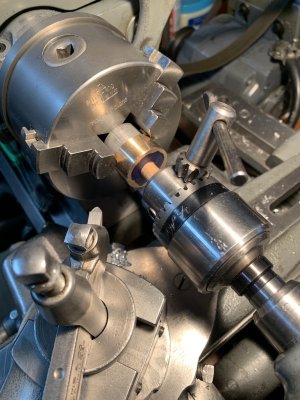
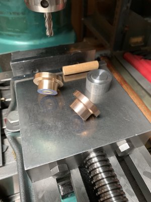
Anyway, the first thing I did was to produce a custom made 1" diameter aluminum spacer as a backing piece for the valve body half. The front face of the spacer is a machined spigot machined to 0.001" smaller in diameter than the 5/8" diameter recess in the half valve body and everything was turned concentric and faced flat all in one setting. The spacer was then reversed in the lathe chuck and machined to its final length and flat faced also.

The purpose of the spacer is to center the valve body piece in the jaws of the chuck, to steady it and to act as an end stop as the rear flat face of the spacer butts against the front body face of the chuck. I was a bit lucky here as the through hole in the chuck, although metric, was quite small, smaller than 1" as the diameter of the spacer has to be smaller than the 1-1/8" OD of the workpiece so everything worked out in that regard.

Now to the interesting part. As expected, due to the condition of the chuck, were the two end faces of the machined spacer going to be dead parallel? No, Not by a long shot. They showed a deviation of 2.5-3 thou. and I wanted the spacer to mike better than a thou. on overall thickness to virtually eliminate any wobble. So what to do?

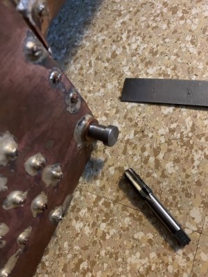
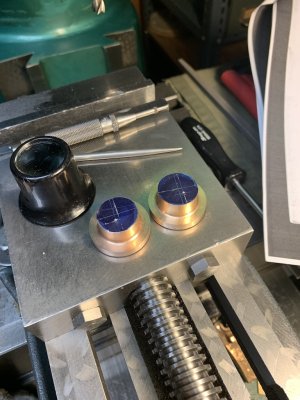
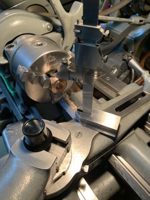
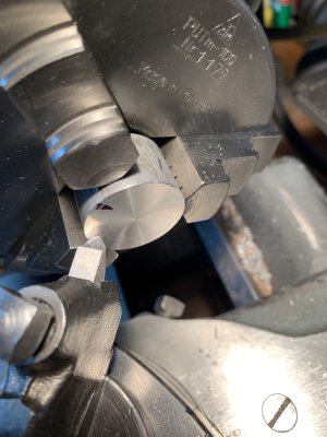
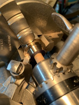
Well, by measuring the spacer thickness with a micrometer every 90 degrees at the OD edge, one can determine the high spot. Mark this with a sharpie pen as shown in the first photo and re - chuck the spacer then bring your cutting tool right up to the face, lock the carriage and advance the cutting tool minutely to see where it scrapes the flat face while turning the lathe spindle by hand. If it does this at the sharpie mark as seen in the photo, all is well and proceed to reface the spacer end. If your cutting tool scrapes somewhere else, back off the jaws slightly, rotate the part in the jaws (say 45 degrees) and repeat the procedure over again until you find the sharpie high point mark.

Now the purists are all going to scream FOUL but it worked! After refacing, the spacer thickness miked 0.0004" deviation between all four readings. Maybe I was just lucky, (as I haven't seen the above described or mentioned before or anywhere else) but I think the procedure "averages out" all of the inaccuracies which the chuck has developed with time.

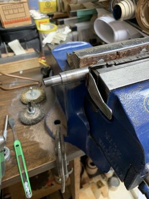
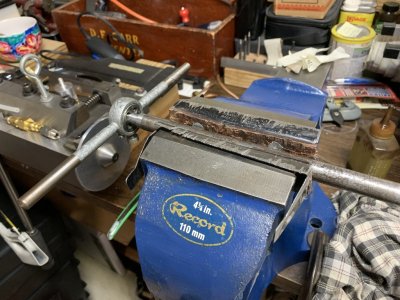
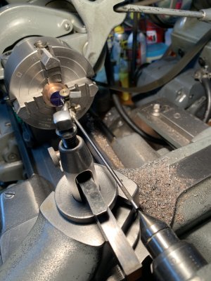
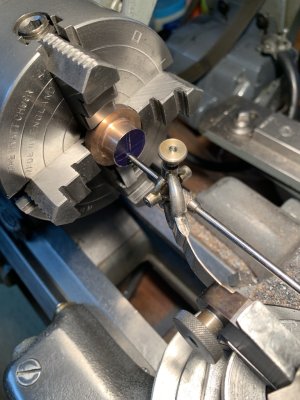
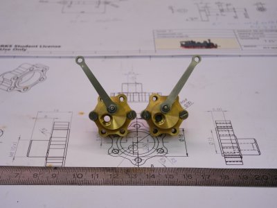
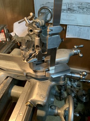
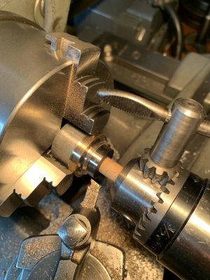
The final setup is as shown in the last photo. As seen, the chuck jaws are barely hanging on to the work and really are there only to provide a turning force. The wooden dowel held in the drill chuck held in the tailstock is there to provide a light seating force so the work can't go anywhere endwise.

I haven't done the actual turning down yet and very light cuts are warranted with a freshly sharpened cutting tool. As the building instructions say to form a radius at the end of the cut, I may have to do the final forming here by turning the lathe chuck by hand.

stay tuned.
 

Attachments

  • 177 An Approach for  Minimizing Holding Errors in Your Three Jaw Scroll Chuck.jpg
    177 An Approach for Minimizing Holding Errors in Your Three Jaw Scroll Chuck.jpg
    214.2 KB · Views: 4
  • 178 The Final Setup I am Using to Start Machining the Rear Portion of the Boiler Blowdown Valv...jpg
    178 The Final Setup I am Using to Start Machining the Rear Portion of the Boiler Blowdown Valv...jpg
    280.6 KB · Views: 4
Last edited:
Hi All,

The first operation on the rear face of valve body halves was successful. But we are not out of the woods yet.

This is going to be a long winded construction thread.
 

Attachments

  • 181 First Operation on Valve Body Half Rear Face Completed.jpg
    181 First Operation on Valve Body Half Rear Face Completed.jpg
    242.8 KB · Views: 9
Hi All,

It just gets trickier and trickier.

Proceeding, I decided no further work on the part until I had made up a test piece and I am glad I did because it solved one problem but created another!

Why did I need to make up a test piece at all?

The problem is the original LBSC construction article which I am using specified a 1/4-40 ME (model engineer) thread on the spigot which threads into the boiler blowdown bushing. The other construction article which I am using specifies a metric 10mm by 1mm spigot thread. Both of these threads are straight threads despital all of the other differences.

However, the thread in the boiler here has a 1/8 NPT which being different to the above and is also different in that it is a tapered thread.

So, I needed to make a test piece with this thread machined into it to check the thread fit in the boiler threaded bushing as tapered threads need to have a sort of interference fit if they are to be steam and pressure tight - that is why they were developed for such purposes.

So looking at the first photo, everything was first turned in the lathe and the 1/8" NPT die was started square in the lathe to start the thread. But as the die has to cut tapered as well as thread, the torque required to do this increases phenomenally so the work was transferred to the bench vise to finish threading to the width of the die which was 3/8". Using plenty of cutting oil and threading in small increments resulted in a very nice finished tapered thread.

Well, in order to do the above I had to clamp the bar in the vise horizontally over its full width using an incredible amount of clamping force and therein lays a problem as how the heck am I ever going to thread a 1/8" NPT on the spigot of the (delicate) bronze valve body half if this much clamping force is needed without totally distorting and /or destroying the workpiece? Now bronze is not as difficult to thread as was the piece of steel but there is no way of doing it directly. I don't have an answer to this problem at the moment and I will have to think about it. In retrospect, this should have been the first operation where one could start with a long bar of bronze and this would not be an issue but...

Now, there is another problem which could have developed but didn't thanks to the test piece. The bushing in the boiler was tapped (and this was several years ago now) but by how much?

When I used a 1/8" NPT plug tap to check the thread, it went in as far in as shown in the third photo. The tap was 2-1/8" long and measured 1-9/16"long when It would not go any further so it had entered 9/16" deep. This nearly gave me a heart attack as I had only left enough material overall on the valve body half to make the spigot thread 9/32" long so it would not have gone far enough in to seal. However, the die threaded test piece would only go in a little more than 1/4" before it stopped (full stop). Boy, was I relieved.

The difference was due to the tap and die as the tap had a lot of relief on the small end while the die had none. So these taper threads can be tricky if one is not used to using them. Lesson learned, don't assume anything and check first.

IF everything works out as designed, the installed valve will end up (in addition to the threaded spigot) with a flange to flange joint (bushing flange butted up against the spigot flange of the valve body) so a belts and braces approach here but that is if everything...
 

Attachments

  • 185 The Die Threaded Test Piece Threads in Only a Tiny Bit More Than One Quarter Inch.jpg
    185 The Die Threaded Test Piece Threads in Only a Tiny Bit More Than One Quarter Inch.jpg
    305.7 KB · Views: 7
  • 184 The One Eight Inch NPT Threading Tap Threads in Nine Sisteen Inches.jpg
    184 The One Eight Inch NPT Threading Tap Threads in Nine Sisteen Inches.jpg
    302 KB · Views: 8
  • 183 The Finished NPT Thread.jpg
    183 The Finished NPT Thread.jpg
    238.8 KB · Views: 8
  • 182 Finish Die Threading the One Eighth Inch NPT.jpg
    182 Finish Die Threading the One Eighth Inch NPT.jpg
    286 KB · Views: 8
Last edited:
There are tapered reams used when cutting female pipe threads, somewhere I have a card showing sizes to use for the various taps. For sure it is in "Machinest's Hand Book". I know, most no one uses them to tap a female pipe thread, however in the case of these small sizes, it may help as some can be a bit testy and breakable, not to say also difficult to start, and get/ keep straight.
Note there is also recommended tapers and lengths to make for male pipe threads.
I have in a pinch drilled a pilot slightly over size and only part of the depth to help get the tap started, must be controlled depth as tap has to remove all of bottom of pilot hole, can be a bear with larger taps to ream out hole and cut threads at the same time.
I hate it when the fitting bottoms out and thread is not tight, or 1 turn or less and every thing is tight! Then it points the wrong way anyhuuw!
Look to be doing a fine job and working the brain too!
 
Hi All,

On to the next operation as it gets worse and worse.

I am deliberately showing every step by step here to show all of the important details left out in all the other construction articles that are out there. Until you actually have to do it yourself, you really don't know what is involved to do it right.

The construction articles which I have say now layout the boiler steam inlet on the rear face of the valve body half, transfer the workpiece to a four jaw chuck, centre punch the location of the steam inlet and proceed to centre drill and drill the steam passage. Sounds simple.

Except the inlet passage is designed eccentric in the backface flange and is offset 1/8" from one centreline and offset a 1/16" from the other centreline of the body half. That is not a problem to layout using a vernier height gauge, some square backing blocks and a small square so I did not show it . It is just fiddly and a third hand would have been most useful.

The steam inlet is then prick and centre punched as shown in the first photo using good lighting and an eye loupe. Next transfer the work to your four jaw. Well, I was fortunate here as I have a quality small 4 jaw but the work could not be held as before in the three jaw as the through hole in this chuck is larger than the OD of the workpiece so you can't use a backup spacer to align the part. But fortunately, the jaws could be reversed and the steps in the jaws provided a perfect seating for the workpiece. See the two middle photos.

Next was to precisely align the punch mark and to do this I used a traditional "wiggler". I have the real deal again made by Starrett purchased some 50 years ago and I don't think they make them any more. Notice how many expensive tools keep coming up to do the simplest of tasks. A wiggler is a very interesting device but I won't go into all of the details of how it is used. You can make one but that's another project in itself.

Now for the issues the above raises. Since the Inlet passage is eccentric, so do the jaws of the 4 jaw chuck need to be eccentric. But there is a severe limit to this when the jaws are reversed and small parts are involved. To pick up the punch mark I had to insert an aluminum shim on one jaw as seen in the last two photos to keep two of the reversed jaws from interfering one with the other. And now the jaws now do not grip the work concentrically so there is a danger the jaw edges will dig into the work which is delicate enough. Because eccentric turning is involved to produce the threaded spigot, one has to be concerned about this as an additional danger but, fortunately, with this particular chuck, the part was both bedded square and held fairly securely in the jaw step. It just happened to work out his way with this particular 4 jaw chuck but I am doubtful one could be as fortunate with any other 4 jaw chuck.
 

Attachments

  • 186 Laying Out Prick and Centre Punching.jpg
    186 Laying Out Prick and Centre Punching.jpg
    260.5 KB · Views: 9
  • 187 Using the Wiggler.jpg
    187 Using the Wiggler.jpg
    270 KB · Views: 9
  • 188 Picking Up the Centre Punch Mark Using a Wiggler.jpg
    188 Picking Up the Centre Punch Mark Using a Wiggler.jpg
    245.1 KB · Views: 9
  • 189 Showing How Quickly One Gets Into Jaw Interference.jpg
    189 Showing How Quickly One Gets Into Jaw Interference.jpg
    205.7 KB · Views: 9
I don't quite follow why you could not use your jaws orientated to the smaller diameter with a parallel or sacrificial backstop material. I see the way you have it you get the benefit of the jaws as a back stop, but don't you risk drilling into it? (assuming its a through hole)?
 
Back
Top